| Issue |
Mechanics & Industry
Volume 21, Number 4, 2020
|
|
|---|---|---|
| Article Number | 405 | |
| Number of page(s) | 11 | |
| DOI | https://doi.org/10.1051/meca/2020024 | |
| Published online | 06 May 2020 | |
Regular Article
Designing and loaded tooth contact analysis of an Archimedean worm gear drive focusing for the connecting teeth of the worm wheel by loaded torques
Department of Mechanical Engineering, University of Debrecen, Debrecen, Hungary
* e-mail: This email address is being protected from spambots. You need JavaScript enabled to view it.
Received:
30
December
2019
Accepted:
18
March
2020
Abstract
The cylindrical worm gear drives are widely used in different mechanical construction such as in the vehicle industry, the robotics, the medical appliances etc. The main property of them is the perpendicular and space bypass axes arrangement. Quite high transmission ratio could be achieved because of the high number of teeth of the worm-wheel and a little number of threads of the worm. More teeth are connected on the worm-wheel at the same time that is why higher loads and power could be transferred. In this research an Archimedean type cylindrical worm gear drive was designed. After the determination of the geometric parameters the computer-aided models were created for the LTCA analysis. Knowing of the kinematic motions of the elements the contact points of the wrapping surfaces could be determined by mathematical way. The necessary coordinate system's arrangements and matrixes were also determined. Different torques were applied during the LTCA. The changing of the distribution of the normal stress and normal deformation into different directions was followed on each connecting tooth of the worm-wheel by the torques. Based on the results consequences were determined by the created diagrams which contain the torques and the analysed mechanical parameter for each tooth.
Key words: LTCA / CAD / Archimedean worm gear drive / torque / mechanical
© AFM, EDP Sciences 2020
1 Introduction
The Archimedean worm can be derived, an inclining with ω angle to basic cylinder and basic cylinder shaft transitory line does consistently rotating and advancing motion around the cylinder (Fig. 1). The AB section of line, which does not change its angle and distance comparing to the basic cylinder shaft during motion, defines Archimedean worm surface [1–6,8,9,20].
Characteristic of originated worm next to these conditions, it gives Archimedean spiral in perpendicular segment for the worm axis at the same time the generators of helical surface always cross through the worm axis [4]. In Figure 1 the A plane segment is shown as the Archimedean spiral curve.
A method used for determining the mathematical relationships that define the spiral is the coordinate transformation, and for the calculation of the points which define it, AutoLISP is used, representation being made in AutoCAD [10].
A matrix–vectorial mathematical model of the double worm-face gear with cylindrical worm and a graphical modelling were presented which is based on the specific geometrical characteristics accomplished by means of the Autodesk Inventor 3D modelling program [11].
A double helical gear transmission with curve element constructed tooth pairs was carried out. Generation and mathematical model of tooth profiles are proposed based on the geometric relationship. Tooth profile equations are derived considering the developed equidistance-enveloping approach [12].
A computation method of the study of worm gears with Archimedean and involute worms was evaluated when engagement correction is presented, based on the contact pressures and the wheel teeth wear, as well as the gear life and the sliding speed in the engagement. The regularities of influence of correction on the stated gears parameters are stated [13].
A complex mathematical model was developed for every worm gear drive and the production of them. This model is also suitable for analysis of different manufacturing technologies [14].
A machining method of large-sized cylindrical worm gears with Niemann profiles using a computer numerical control (CNC) machining centre is proposed. For this study, the tooth contact pattern and transmission errors of large-sized worm gear pair with Niemann profiles are analysed before machining of the worm and worm wheel. Next, the machining conditions of worm are determined calculating each offset distance between the worm axis and the centre axis of the end mill, and then the worm is machined by swarf cutting that means machining by the side surface of the end mill. The tooth profiles of worm wheel are modelled using a 3D computer-aided design [15].
A special case of machining was presented in a cylindrical worm with a fixed and variable pitch. The worm is machined with a cylindrical finger-type mill positioned perpendicularly to the worm axes. The axial profile and the axial profile angle of the worm were calculated and measured [16].
Geometric interference can occur in cylindrical worm gear set that makes use of oversized hob to cut the worm gear. In particular, the interference occurs easily in the design with high lead and low pressure angles. The interference results in a corner contact. In this study, they examined the influence of the machine tool setting errors of the worm gear hobbing and the influence of the shaft misalignments of the worm gear set on the interference [17].
This study examined the geometric interference of cylindrical worm gear drives using an oversized hob to cut the worm gear. The instantaneous line contact of a fully conjugated gear set becomes an instantaneous point contact when an oversized hob is used. In this type of worm gear drive, however, an edge contact can occur between the worm and worm gear. The edge contact is caused by geometric interference, and it occurs regardless of the presence of elastic deformation, misalignment, and transmission error [18].
A single enveloping worm gear of cylindrical worm gear drive is cut by an oversized hob. The oversize provides a longitudinal crowning on the worm gear tooth surface. However, when a lead angle of the worm becomes higher, the longitudinal crowning becomes more asymmetric. The asymmetrically crowned worm gear surface makes the gear contact more sensitive to the certain direction of misalignment [19].
A mathematical model is presented for the determination of the tooth surface of the worm-wheel machined by either the tangential or the radial method. Worm-wheel machining with a special hob and a modular hob is considered. Different methods of solving the task are presented. This also includes a numerical method that requires the envelope condition to be solved [20].
2 Determination of the geometric parameters
Knowing of the input parameters of the designing process (a, q, max, z1, z2, αax) the other necessary geometric parameters could be determined based on the references (Fig. 2) [2,4–8]. The standardized backlash (jax) between the teeth could be selected in the function of the axial module [7].
The necessary worm length is [7]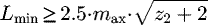 (1)
(1)
The medium face width of the worm-wheel is [7] (2)
(2)
The tooth thickness of the worm in axial section is [7]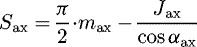 (3)
(3)
The breaking angle of the teeth of the worm-wheel is [7] (4)
(4)
Using of the GearTeq software which is built up beside the SolidWorks software many different drive pairs could be designed (spur gears, helical gears, bevel gears, worm gear drives, etc.). Knowing of the appropriate input parameters and the reference's recommendations [1,2,4–8] this software can determine the missing geometric parameters of a given drive pair and visualize the wireframe model of them. Redesigning of the geometric parameters could be possible if we want to design a unique gear pair.
After the successful designing the CAD models of the elements could be saved into the SolidWorks software where assembly, connection analysis and beat examination could be done before the TCA.
We designed an Archimedean worm gear drive on which LTCA will be done. The realistic CAD model and the calculated parameters of our-designed worm gear drive could be seen on Figure 3 and Table 1.
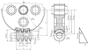 |
Fig. 2 Geometric parameters of the Archimedean worm gear drive. |
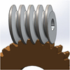 |
Fig. 3 CAD model of the designed worm gear drive. |
Calculated parameters of the designed worm gear drive.
3 Determination of the contact points by mathematical way
The profile curve  of the worm is made as a result of a rotation and linear movements at the same time during the worm production. The K1R (x1R, y1R, z1R) rotating coordinate system related to the worm on which the worm can be rotated [1,2,5–8,10,14,21–23].
We are looking for the surface connected to K2R coordinate system related to  . The 2 surfaces during their movements coincide. Taking into consideration the following correlation
 (5)
(5)
the movement can be described with (ϕ1R) movement parameter [1,2,5–8,10,14,21–23].
The relative velocity between the 2 surfaces can be determined by the transformation between the rotating K1R coordinate system of the worm and the rotating K2R coordinate system of the worm-wheel: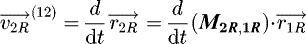 (6)
(6)
Taking into consideration the correlation between the velocity vectors of the relative movement in K1R and K2R coordinate systems [1,2,5–8,10,14,21–23]: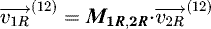 (7)
(7)
in K1R coordinate system, the relative velocity vector, based on (6) is: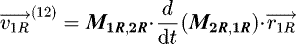 (8)
(8)
Transformation matrices between the K1R and K2R coordinate systems (Fig. 4.):
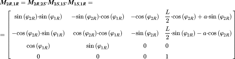 (9)
(9)
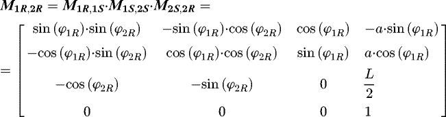 (10)
(10)
The P1k is the kinematic mapping matrix: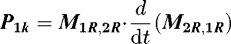 (11)
(11)
where: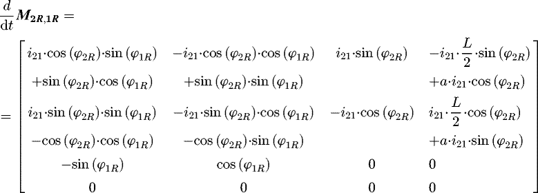 (12)
(12)
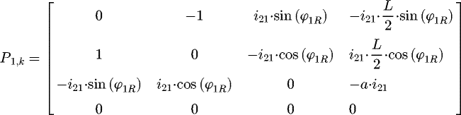 (13)
(13)
The contact points mutually covering each other on the tooth connection zone can be determined by solving the connection equation − which expresses the 1st Law of Contact − and the vector-scalar function simultaneously [1,2,5–8,10,14,21–23]: (14)
(14)
The contact points between the elements could be calculated by the common solution of the following equations [1,2,5–8,10,14,21–24]: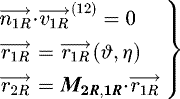 (15)
(15)
Knowing the geometric parameters of the worm gear drive and the above mentioned equations a computer program could be developed with which the contact points could be determined and represented in the function of the discreet ϕ1R, ϕ2R angular displacements.
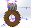 |
Fig. 4 Connection between the coordinate systems of the worm gear drive pair. |
4 LTCA
The TCA is necessary for the determination and analysis of the mechanical parameters on the tooth contact zone by loads. This load could be torques, forces or pressures. If static structural is used, the TCA is called LTCA [12,13,25,26]. The purpose is the analysis of the mechanical parameters before the real production and real working on a construction. If modifications are needed, we can return to the designing process and modify either input parameter or overwrite one or more calculated parameter.
4.1 Material quality, FE mesh (finite element)
The property of the material used for our designed worm gear drive (the worm and the worm-wheel) is given in Table 2.
Controlled meshing was used for the analysis because of the achievement of the more punctual results. The element size was 0.5 mm on the tooth contact zone. Automatic meshing was used on the outside areas (Fig. 5). A friction coefficient µ = 0.01 was defined between the connecting teeth. The number of used elements was 1 099 021. The meshing method was tetrahedrons.
Material properties.
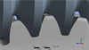 |
Fig. 5 FE mesh. |
4.2 Loads and boundary conditions
Eight coordinate systems were defined for LTCAs: Ks1–static related to the worm, Ks2–static, related to the worm-wheel and two coordinate systems for each connecting tooth of the worm-wheel in the tooth contact zone. Three teeth of worm-wheel are connected to the worm at the same time (Figs. 5 and 6).
Five degrees of freedom were fixed of the worm, only rotation along the rotational axis of the worm was allowed. The worm was loaded by M = 500–700 Nm torque by 50 Nm steps. Six degrees of freedom of the worm-wheel were fixed.
During the analysis normal stress and normal deformation were analysed for each loaded tooth of the worm wheel into normal (perpendicular direction for the teeth surface of the worm-wheel), radial and axial directions.
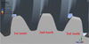 |
Fig. 6 Teeth connection of the worm gear drive. |
4.3 Normal stress' analysis
The normal stress distribution could be seen in Figure 7 for each connected tooth of the worm-wheel and the worm surface.
Based on Figure 8 the highest normal stress results were received on the 2nd connected tooth in absolute value that is why it was loaded the best. The lowest stresses were received on the 1st connected tooth. The shape of the diagram is linear. Continuously increasing differences in the function of the torque could be observed between the stress values on each discreet torque.
The axial stress distribution could be seen in Figure 9 for each connected tooth of the worm-wheel and the worm surface.
Based on Figure 10 the highest axial directional stress results were received on the 1st tooth. These values are continuously being increased in the function of the torque in absolute value.
The lowest results were received on the 2nd tooth. The results are continuously being increased in the function of the torque. The sign of the normal stress is positive on the 2nd tooth (Fig. 10).
The stress results are continuously being decreased in the function of the torque on the 3rd tooth in absolute value (Fig. 10).
The highest stress values are on the 1st tooth. The stresses are lower on the 2nd tooth than on the 3rd tooth until 650 Nm torque in absolute value. In case of 700 Nm the stress on the 2nd tooth is higher than on the 3rd tooth.
The radial directional stress distribution could be seen in Figure 11 for each connected tooth of the worm-wheel and the worm surface.
Based on Figure 12 the highest normal stress results were received on the 2nd connected tooth in absolute value. The lowest stresses were received on the 1st connected tooth. The shape of the diagram is linear. Continuously increasing differences in the function of the torque could be observed between the stress values on each discreet torque. The 2nd tooth was loaded the best.
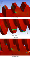 |
Fig. 7 Normal stress distribution on the connecting surfaces of the elements (M = 600 Nm). (a) Worm-wheel, (b) worm, (c) mating area. |
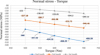 |
Fig. 8 Average normal stress results on the worm-wheel's tooth surfaces in the function of the loaded torque. |
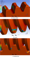 |
Fig. 9 The axial directional stress distribution on the connecting surfaces of the elements (M = 600 Nm). (a) Worm-wheel, (b) worm, (c) mating area. |
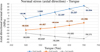 |
Fig. 10 Average axial directional normal stress results on the worm-wheel's tooth surfaces in the function of the loaded torque. |
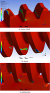 |
Fig. 11 Radial directional stress distribution on the connecting surfaces of the elements (M=600 Nm). (a) Worm-wheel, (b) worm, (c) mating area. |
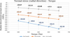 |
Fig. 12 Average radial directional normal stress results on the worm-wheel's tooth surfaces in the function of the loaded torque. |
4.4 Normal deformation's analysis
The normal stress distribution could be seen in Figure 13 for each connected tooth of the worm-wheel and the worm surface.
Based on Figure 14 the highest normal deformation results were received on the 2nd tooth. The results were almost the same in case of the 1st and 3rd tooth. The normal deformation is continuously being increased in the function of the increscent torque in absolute value.
The axial normal deformation distribution could be seen in Figure 15 for each connected tooth of the worm-wheel and the worm surface.
Based on Figure 16 the highest axial directional normal deformation results were received on the 3rd tooth. The lowest results were received on the 1st tooth. The axial directional normal deformation is continuously being decreased in the function of the increscent torque.
The radial normal deformation distribution could be seen in Figure 17 for each connected tooth of the worm-wheel and the worm surface.
Based on Figure 18 the highest radial directional normal deformation results were received on the 2nd tooth in absolute value. The results were almost the same in case of the 1st and 3rd tooth. The radial directional normal deformation is continuously being increased in the function of the increscent load torque. Higher differences could be observed between the results of the 1st and 2nd teeth than between the results of the 1st and 3rd teeth on each discreet torque.
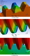 |
Fig. 13 Normal deformation distribution on the connecting surfaces of the elements (M = 600 Nm). (a) Worm-wheel, (b) worm, (c) mating area. |
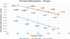 |
Fig. 14 Average normal deformation results on the worm-wheel's tooth surfaces in the function of the loaded torque. |
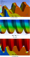 |
Fig. 15 Axial directional normal deformation distribution on the connecting surfaces of the elements (M = 600 Nm). (a) Worm-wheel, (b) worm, (c) mating area. |
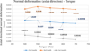 |
Fig. 16 Average axial directional normal deformation results on the worm-wheel's tooth surfaces in the function of the loaded torque. |
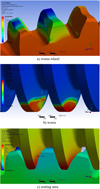 |
Fig. 17 Radial directional normal deformation distribution on the connecting surfaces of the elements (M = 600 Nm). (a) Worm-wheel, (b) worm, (c) mating area. |
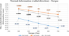 |
Fig. 18 Average radial directional normal deformation results on the worm-wheel's tooth surfaces in the function of the loaded torque. |
5 Conclusion
The aim of this research is the analysis of the mechanical parameters for each tooth of the worm-wheel during the tooth connection. Previously, a new Archimedean type worm gear drive was designed. The GearTeq software is a complex gear designer software and was used for the ease of the designing process. Knowing the references' recommendations, all of the gear drive's parameters could be determined with the help of this software. The user has to know the appropriate tooth geometric studies for the appropriate usage of this software. After the geometric analysis the CAD models of the elements could be prepared by SolidWorks software. They are indispensable for the TCA.
The manufacturing costs are significantly high for the production of a toothed element because usually special cutting tool is needed and also because of the designing cost, worker's cost, the machine cost, the overhead cost, etc. Consequently, geometrically corrected tooth elements have to be manufactured. Many errors could be eliminated by the TCA. After the analysis if there is a mechanical problem, the designer can return to the designing or modelling process or if it is needed, they can select another workpiece material or modify the loads.
Three worm-wheel's teeth are connected by the worm at the same time that is why the LTCA was created for three teeth. The load torques (M = 500–700 Nm) were selected by 50 Nm discreet step. Based on these loads the normal stresses and normal deformations were analyzed for each tooth in case of normal, axial and radial directions. The calculated average values are represented in diagrams. Based on the shape of the diagrams we determine the statements.
The total normal stress results could be seen in Figures 8, 10 and 12 for each tooth. The following consequences could be determinable:
-
1st tooth: the highest normal stress is the normal stress which is interpreted perpendicularly for the tooth surface. The lowest is the axial directional normal stress in absolute value. The axial directional stress values are much lower than the other stress' values. All of the stresses are continuously being increased in the function of the increscent load torque.
-
2nd tooth: the highest normal stress is the normal stress which is interpreted perpendicularly for the tooth surface. The lowest is the axial directional stress in absolute value. The axial directional stress values are much lower than the other stress' values. The shape of the axial directional stress's line is increscent in the function of the increscent load torque considering the signs.
-
3rd tooth: the highest normal stress is the normal stress which is interpreted perpendicularly for the tooth surface. The lowest is the axial directional stress in absolute value. The axial directional stress values are much lower than the other stress' values. The axial directional normal stress is continuously being decreased in the function of the increscent load torque. In contrast the other stresses are continuously being increased because of the torque's effect in absolute value.
-
the lowest stresses appeared on the 1st tooth. The highest stresses appeared on the 2nd tooth because it is situated in the middle of the tooth connection.
The total normal deformation results could be seen in Figures 14, 16 and 18 for each tooth. The following consequences could be determinable:
-
1st tooth and 2nd tooth: the highest is the radial directional deformation. The axial directional deformation is much lower than the other deformations. The axial directional deformations are continuously being decreased in the function of the increscent load torque. In contrast the other deformations are continuously being increased in the function of the increscent load torque.
-
3rd tooth: the normal deformation which is perpendicular for the tooth surface and the radial directional deformation are almost the same. The differences between them are a few. The highest is the normal deformation into perpendicular direction. The axial directional normal deformations are continuously being decreased in the function of the increscent load torque. In contrast the other deformations are continuously being increased in the function of the increscent load torque.
-
The lowest axial deformations appeared on the 1st tooth. The highest values appeared on the 3rd tooth.
-
The highest normal and radial directional deformations are received on the 2nd tooth. The lowest values are received on the 3rd tooth.
Nomenclature
 (mm/min−1):
Relative velocity vector
(mm/min−1):
Relative velocity vector
 :
Normal vector of the surface in K1R coordinate system
:
Normal vector of the surface in K1R coordinate system
 :
Placement vector of the moving points of the profile curve
:
Placement vector of the moving points of the profile curve
 :
Placement vector of moving point of conjugated surface
:
Placement vector of moving point of conjugated surface
M2R,1R, M1R,2R : Translation matrices between K1R and K2R coordinate systems
P1 k : Matrix of kinematic mapping
 :
M2R,1R derivative matrix
:
M2R,1R derivative matrix
O1R, O1S, O2R, O2S : Origins of the appropriate coordinate systems
K1R (x1R, y1R, z1R): Rotational coordinate system related to the driver gear wheel
K1S (x1S , y1S , z1S ): Static coordinate system related to the driver gear wheel
K2R (x2R , y2R , z2R ): Rotational coordinate system related to the driven gear wheel
K2S (x2S , y2S , z2S ): Static coordinate system related to the driven gear wheel
ϕ1R , ϕ2R (°): Angular displacement
x, y, z (mm): Coordinates
L (mm): Worm length
max (mm): Axial module
mn (mm): Normal module
z1 : Number of threads of the worm
z2 : Number of teeth of the worm-wheel
b2 (mm): Face width of the worm-wheel
d01, d02 (mm): Pitch diameter
da1, da2 (mm): Outside diameter
df1, df2 (mm): Root diameter
ha1, ha2 (mm): Addendum
hf1, hf2 : Dedendum
H : Whole depth of thread
i21, i : Transmission ratio
js (mm): Backlash
Sax1, Sax2 (mm): Tooth thickness
Pd (mm): Diametral pitch
Pdn (mm): Normal diametral pitch
ϕ (°): Breaking angle
γm (°): Lead angle
px (mm): Worm lead of thread
t0 (mm): Circular pitch of the worm-wheel
f': Addendum coefficient
r': Fillet coefficient
a (mm): Center distance
αax (°): Pressure angle
αn (°): Normal pressure angle
r (mm): Fillet radius
M (Nm): Load torque
µ: Friction coefficient
TCA: Tooth Contact Analysis
LTCA: Loaded Tooth Contact Analysis
CAD: Computer Aided Designing
Acknowledgments
This research was supported by the János Bolyai Research Scholarship of the Hungarian Academy of Sciences.
References
- K. Bányai, Hengeres csigák gyártásgeometriája és ellenőrzése, University Doctoral Dissertation, Miskolc, 1977 [Google Scholar]
- L. Dudás, The Theory and Practice of Worm Gear Drives, Penton Press, London, 2000 [Google Scholar]
- L. Dudás, Modelling and simulation of a new worm gear drive having point-like contact, Eng. Comput. 29, 251–272 (2013) [Google Scholar]
- D. Maros, V. Killman, V. Rohonyi, Csigahajtások, Műszaki Könyvkiadó, Budapest, 1970 [Google Scholar]
- F.L. Litvin, A. Fuentes, Gear Geometry and Applied Theory, Cambridge University Press, Cambridge, 2004 [Google Scholar]
- D.W. Dudley, Gear Handbook, MC Graw Hill Book Co., New York, 1962 [Google Scholar]
- Z. Terplán, Gépelemek IV., Kézirat, Tankönyvkiadó, Budapest, 1975. p. 220. [Google Scholar]
- S.P. Radzevich, Dudley's Handbook of Practical Gear Design and Manufacture, 3rd edn., CRC Press, Boca Raton, 2012, p. 656 [Google Scholar]
- S. Bodzás, I. Dudás, Production geometry and finite element method analisys of archimedean worm gear drive, microCAD 2011, XXV. International Scientific Conference, Miskolci Egyetem Innovációs és Technológia Transzfer Centrum , 2011, pp. 29–34 [Google Scholar]
- S.C. Albu, The coordinate transformations method combined with autolisp to the archimedean spiral representation in AutoCAD, Sci. Bull. Petru Maior Univ. Tîrgu Mureş, 12, 22–25 (2015) [Google Scholar]
- C. Bolos, M. Ciotea, B. Bucur, V. Bolos, Modelling the double worm-face gears, J. Ind. Des. Eng. Graph. 10, 1–4 (2015) [Google Scholar]
- D. Liang, T. Luo, R. Tan, Generation and meshing analysis of a new type of double helical gear transmission, Hindawi, Math. Prob. Eng. 2018, 1–10 (2018) [Google Scholar]
- M.V. Chernets, Prediction method of contact pressures, wear and life of worm gears with Archimedean and involute worm, taking tooth correction into account, J. Friction Wear 40, 342–348 (2019) [CrossRef] [Google Scholar]
- I. Dudás, The extension of the general mathematical model developed for helicoidal surfaces to the whole system of manufacturing technology and production geometry (ProMAT), Int. J. Adv. Manuf. Technol. 86, 1557–1572 (2016) [Google Scholar]
- K. Kawasaki, I. Tsuji, Machining method of large-sized cylindrical worm gears with Niemann profiles using CNC machining center, Int. J. Adv. Manuf. Technol. 104, 3717–3729 (2019) [Google Scholar]
- T. Nieszporek, P. Boral, Examination of the cylindrical worm profile, MATEC Web Conf. 94, 07007 (2017) [CrossRef] [EDP Sciences] [Google Scholar]
- J. Sohn, N. Park, Study on the influence of gear hobbing and shaft misalignments on the geometric interference of cylindrical worm gear set, J. Mech. Eng. Sci. 231, 1–9 (2016) [Google Scholar]
- J. Sohn, N. Park, Geometric interference in cylindrical worm gear drives using oversized hob to cut worm gears, Mech. Mach. Theory 100, 83–103 (2016) [Google Scholar]
- J. Sohn, N. Park, Modified worm gear hobbing for symmetric longitudinal crowning in high lead cylindrical worm gear drives, Mech. Mach. Theory 117, 133–147 (2017) [Google Scholar]
- T. Nieszporek, R. Gołębski, L. Soos, Analysis of the worm-wheel toothing accuracy. Tech. Gaz. 24, 993–1000 (2017) [Google Scholar]
- F.L. Litvin, Gear geometry and applied theory, Englewood Cliffs, Prentice Hall, NJ, 1994 [Google Scholar]
- F.L. Litvin, Development of Gear Technology and Theory of Gearing, NASA Reference Publication 1406, Chicago, 1998 [Google Scholar]
- F.L. Litvin, Theory of Gearing, NASA Reference Publication 1212, 1989 [Google Scholar]
- S. Bodzás, Kúpos csiga-, tányérkerék-, és szerszám felületek kapcsolódásának elemzése, PhD dissertation, University of Miskolc, 2014 [Google Scholar]
- S. Moaveni, Finite Element Analysis, Theory and Application with ANSYS, Pearson Education Limited, London, 2015, p. 928 [Google Scholar]
- F.L. Litvin, I. Gonzalez-Perez, K. Yukishima, A. Fuentes, K. Hayasaka, Design, simulation of meshing, and contact stresses for an improved worm gear drive, Mech. Mach. Theory, 42, 940–959 (2007) [Google Scholar]
Cite this article as: S. Bodzás, Designing and loaded tooth contact analysis of an Archimedean worm gear drive focusing for the connecting teeth of the worm wheel by loaded torques, Mechanics & Industry 21, 405 (2020)
All Tables
All Figures
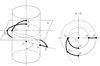 |
Fig. 1 Derivation of Archimedean worm [9]. |
| In the text | |
|
Fig. 2 Geometric parameters of the Archimedean worm gear drive. |
| In the text | |
|
Fig. 3 CAD model of the designed worm gear drive. |
| In the text | |
|
Fig. 4 Connection between the coordinate systems of the worm gear drive pair. |
| In the text | |
|
Fig. 5 FE mesh. |
| In the text | |
|
Fig. 6 Teeth connection of the worm gear drive. |
| In the text | |
|
Fig. 7 Normal stress distribution on the connecting surfaces of the elements (M = 600 Nm). (a) Worm-wheel, (b) worm, (c) mating area. |
| In the text | |
|
Fig. 8 Average normal stress results on the worm-wheel's tooth surfaces in the function of the loaded torque. |
| In the text | |
|
Fig. 9 The axial directional stress distribution on the connecting surfaces of the elements (M = 600 Nm). (a) Worm-wheel, (b) worm, (c) mating area. |
| In the text | |
|
Fig. 10 Average axial directional normal stress results on the worm-wheel's tooth surfaces in the function of the loaded torque. |
| In the text | |
|
Fig. 11 Radial directional stress distribution on the connecting surfaces of the elements (M=600 Nm). (a) Worm-wheel, (b) worm, (c) mating area. |
| In the text | |
|
Fig. 12 Average radial directional normal stress results on the worm-wheel's tooth surfaces in the function of the loaded torque. |
| In the text | |
|
Fig. 13 Normal deformation distribution on the connecting surfaces of the elements (M = 600 Nm). (a) Worm-wheel, (b) worm, (c) mating area. |
| In the text | |
|
Fig. 14 Average normal deformation results on the worm-wheel's tooth surfaces in the function of the loaded torque. |
| In the text | |
|
Fig. 15 Axial directional normal deformation distribution on the connecting surfaces of the elements (M = 600 Nm). (a) Worm-wheel, (b) worm, (c) mating area. |
| In the text | |
|
Fig. 16 Average axial directional normal deformation results on the worm-wheel's tooth surfaces in the function of the loaded torque. |
| In the text | |
|
Fig. 17 Radial directional normal deformation distribution on the connecting surfaces of the elements (M = 600 Nm). (a) Worm-wheel, (b) worm, (c) mating area. |
| In the text | |
|
Fig. 18 Average radial directional normal deformation results on the worm-wheel's tooth surfaces in the function of the loaded torque. |
| In the text | |
Current usage metrics show cumulative count of Article Views (full-text article views including HTML views, PDF and ePub downloads, according to the available data) and Abstracts Views on Vision4Press platform.
Data correspond to usage on the plateform after 2015. The current usage metrics is available 48-96 hours after online publication and is updated daily on week days.
Initial download of the metrics may take a while.