| Issue |
Mechanics & Industry
Volume 22, 2021
|
|
|---|---|---|
| Article Number | 45 | |
| Number of page(s) | 10 | |
| DOI | https://doi.org/10.1051/meca/2021045 | |
| Published online | 10 November 2021 | |
Regular Article
An improved negative zero vibration anti-swing control strategy for grab ship unloader based on elastic wire rope model
1
School of Logistics Engineering, Wuhan University of Technology, Wuhan 430063, China
2
Engineering Research Center of Port Logistics Technology and Equipment, Ministry of Education, China
3
School of Mechanical Engineering, Southeast University, Nanjing 210096, China
* e-mail: This email address is being protected from spambots. You need JavaScript enabled to view it.
Received:
7
August
2020
Accepted:
14
October
2021
Abstract
A dynamic model of swing system of bridge-type ship unloader is established by considering the elastic factor of wire rope in this paper. Based on this model, an improved Negative Zero Vibration (NZV) shaper with optimal control parameters of variable rope length system is proposed to restrain the swing of grab. Then the control effects, influence of elasticity factor and parameter sensitivities are analyzed based on numerical simulation. The results show that the proposed control strategy can reduce the working cycle time of the grab ship unloader about 11% when considering the elastic factor of the wire rope, and the grab's maximum residual swing angle decreases by 67% when discharging at full load, and decreases by 79% when taking the cargos at empty load. This implies that the improved NZV control method provides better swing angle control performance and shorter operation time compared with the Zero Vibration (ZV) and Zero Vibration and Derivative (ZVD) methods. Moreover, elastic rope model can improve the swing angle control effect of grab based on the proposed control strategy compared with rigid rope model. The parameter sensitivity analysis displays that the grab's maximum residual swing angle by using the improved NZV method is sensitive to the change of the grab's center of gravity, and this angle is more sensitive to the wire rope diameter deviation compared with the elastic modulus deviation.
Key words: Grab ship unloader / elastic wire rope model / negative zero vibration / anti-swing control
© X. Cao et al., Published by EDP Sciences 2021
 This is an Open Access article distributed under the terms of the Creative Commons Attribution License (https://creativecommons.org/licenses/by/4.0), which permits unrestricted use, distribution, and reproduction in any medium, provided the original work is properly cited.
1 Introduction
The hoisting swing of crane will seriously affect its efficiency and even induce safety problems. As an open-loop control method, input shaping technology has been widely studied and applied in the swing control of crane, as it does not need feedback sensors and is faster to suppress oscillation than anything possible with feedback control [1].
The classical input shaper is the Zero Vibration (ZV) shaper that was initially proposed in the 1950's [2]. When the frequency and damping ratio of the dynamic system remain unchanged, it can effectively suppress residual vibration of the system. Nevertheless, the typical ZV shaper is less robust to modeling errors and is not suitable for the system with changeable frequency and damping ratio. For this, some robustness methods such as Zero Vibration and Derivative (ZVD) shaper [3], Extra-Insensitive (EI) shapers [4] and Specified-Insensitivity (SI) shaper [5] were proposed. Unfortunately, robust shapers usually extend the tuning time of the system, which reduces the system response speed [6–8]. For example, the vibration period of the ZVD shaper is half longer than that of the ZV shaper, which has a little effect on most high-frequency systems. However, increasing the oscillation period by half will seriously affect the transportation efficiency for crane equipment which usually works with large rope lengths. In order to speed up the response time, the input shapers with negative impulses are also be studied [9]. The disadvantage of the negative impulse shaper is that it may lead to a reduction in robustness costs and may excite high-frequency modes [10–12].
Since the input shaping technology relies on the system model, the dynamic model of the swing system is very important for the crane. For the research of input shaping technology on bridge type crane, the single pendulum model is the simplest and most widely used model. For example, Singer et al. [13] proposed a fixed-period shaper to reduce residual oscillation of gantry crane by establishing a crane single pendulum model. Singhose et al. [14,15] evaluated various types of input shapers that are compared with time-optimal rigid body commands over a large parameter rang for the gantry cranes that were simplified by single pendulum models. Hong et al. [16] studied an improved command shaper to reduce residual oscillations of the load that was treated as a single pendulum during the operation of the crane trolley. Sorensen et al. [17] proposed a control method to achieve precise positioning of a crane load using single pendulum model, in which an input shaper was used to reduce the motion-induced swing, and a feedback control was adopted for location and disturbance suppression. Stergiopoulos and Tzes [18] proposed an adaptive input shaper to suppress the oscillation of the payload that was simplified by a single pendulum model on an overhead crane. Garrido et al. [19] used the online two-dimensional inclinometer to measure swing angle and calculated input impulse trains online in terms of single pendulum model to realize the anti-sway control of the overhead crane. Ngo et al. [20] studied the combination method of bang/off-bang control scheme and input shaping for container cranes. Veciana et al. [21–23] used the pulse convolution multiplied by a negative exponent time function to define the motion profiles considering damping and proposed a design method of command input to reduce the residual vibration of the crane single pendulum model under non-zero initial state. Zhou et al. [24] proposed an improved ZV method to control the payload swing of grab ship unloader considering single pendulum model with variable rope length. Arabasi and Masoud [25] investigated a new input shaper applied to overhead crane, which involved simultaneous lifting and moving operations. Maghsoudi et al. [26] proposed an improved input shaping method to effectively control the swing of a nonlinear model with friction for overhead crane, in which a particle swarm optimization algorithm was used. Abdullahi et al. [27] adopted a new command shaping technology based on online adaptive output to effectively reduce the payload sway of an overhead crane considering the influence of payload hoisting and wind disturbance. Ramli et al. [28] proposed an improved input shaper to minimize the swing of the overhead crane payload, in which the payload hoisting and payload mass variations were considered.
In order to improve control precision, some researchers have also developed the input shaping schemes based on the crane's double pendulum model. For example, Singhose et al. [29–31] established a double pendulum model of an overhead crane and proposed a new input shaper to suppress the multi-mode oscillations. Vaughan et al. [32] presented a command generation scheme based double-pendulum dynamics to suppress the oscillatory with robustness to frequency changes for tower crane. Masoud et al. [33–35] developed a hybrid input shaping method based on the double-pendulum dynamic model to generate acceleration commands to control operation and swing of overhead crane.
However, the elasticity of wire ropes was often ignored in existing crane models which may cause the model to deviate from the actual system, thereby affecting the control accuracy. Therefore, this paper studies the dynamics of swing system of bridge-type ship unloader by considering the elastic factor of wire rope, and an improved Negative Zero Vibration (NZV) input shaper for optimal control parameters of variable rope length system is proposed to suppress the payload's swing. In addition, the virtual prototype of grab ship unloader is also built to study the swing angle control.
The structure of this paper is as follows. Section 2 establishes a dynamic model of trolley-grab system for the grab ship unloader, where the elastic factor of wire rope is considered. An improved NZV input shaper is proposed in Section 3. Section 4 presents the numerical simulation results. The last section puts forward the conclusions of this paper and future research prospects.
2 Dynamic model of the trolley-grab system considering the elasticity of the wire rope
Figure 1 shows a 3D model of a grab ship unloader. The dynamic model of crane's trolley-payload system is usually simplified as a simple pendulum model or a more elaborate double pendulum model. However, in these models the drum of lifting mechanism was simplified as a hanging point of the trolley, in which the radius of the fixed pulley was ignored. At the same time, the wire rope was treated as a rigid rope, and the influence of the elastic factor on the swing angle of payload was also neglected.
In this paper, the dynamic model of trolley-grab system of grab ship unloader is formulated, in which the elasticity of wire rope is considered. Firstly, this paper makes following assumptions:
-
Considering the elastic factor of the wire rope, it is assumed that the wire rope extends in a manner which complies approximately with Hookes Law, i.e. stress is proportional to strain, then it can be obtained that the stiffness coefficient of wire rope k is a constant about the Elastic Modulus of wire rope material E, the cross-sectional area of wire rope A, and the wire rope length of winding system L (k =EA/L).
-
The lifting drum is simplified as a fixed pulley with a radius connected to the center of gravity of the trolley.
-
Ignoring the friction between the wire rope and the fixed pulley, and excluding the influence of the wind and air damping.
-
Taking the grab as a mass point and ignoring the quality of the wire rope.
-
The trolley and the grab move on the same plane.
The center of gravity of the trolley is taken as Ot (xt, yt), then the inertial coordinate system can be established as Ot-XY. The dynamic model of the trolley-grab swing system with the elastic wire rope is also obtained as shown in Figure 2, in which, Og(xg, yg) is the center of gravity for the grab; mt is the quality of the trolley; mg is the quality of the grab; θ is the angle between the wire rope and the vertical direction; k1 is the stiffness coefficient of the lifting rope; b1 is the damping coefficient of the lifting rope; l is the length of the hoisting rope for a certain moment; h is the amplitude of the grab along the direction of lifting rope due to the rope elasticity; Mhd, Jhd, ϕhd, and rhd are driving torque, moment of inertia, angular displacement and radius of fixed pulley (drum) respectively; f is friction between the trolley and the rail; F is driving force of trolley at horizontal direction; g is the gravity acceleration.
The model in Figure 2, has four generalized coordinates, namely the displacement of the trolley x, the angular displacement of fixed pulley ϕhd, the amplitude of the grab along the direction of lifting rope h, and the grab swing angle θ. If the initial length of the hoisting rope is l0, the rope length can be obtained according to the geometric relationship: (1)in which, Δh is the elongation of hoisting rope when the system is in the initial static equilibrium state. That is expressed in formula by
 (2)
(2)
Then the position coordinates of the trolley and the grab are: (3)
(3)
The velocity components of the trolley and the grab are:
 (4)
(4)
Let Vt be the trolley's velocity, and Vg be the grab's velocity, then the system's kinetic energy is: (5)
(5)
In equation (5), (6)
(6)
Substituting equation (4) and equation (6) into equation (5) results in
 (7)
(7)
Taking Ot height as the zero potential energy level, one can get the system potential energy as follows (8)
(8)
Substituting yg in equation (3) into equation (8), one can get (9)
(9)
The dissipation energy of the system is (10)in which, bhd is the damping coefficient of the lifting drum.
According to the Lagrange's equation, the following system dynamic equation can be obtained (11)in which L = T–V, i.e. Lagrange function; qk (k = 1,2,3,4) is the generalized coordinate, while q1 = x, q2 = ϕhd, q3 = h, and q4 = θ; and Qk is the generalized force in the direction of generalized coordinate, while Q1 = F–f, Q2 = M, Q3 = 0, and Q4 = 0. Thus, the differential equation of motion of the system can be obtained by
 (12)
(12)
Since the velocity of the trolley  and the angular velocity of the lifting drum
  are known in the actual control system, they can be used as input parameters, and the acceleration of the trolley
  and the angular acceleration of the lifting drum
  can be obtained by
  and
and  respectively. Then the swing angle θ can be obtained by the following coupling equations:
 (13)
(13)
If the equation (12) does not consider the elasticity factor of the wire rope and the radius of the lifting drum, it is consistent with the motion differential equation of undamped system of existing single pendulum model.
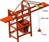 |
Fig. 1 3D model of a grab ship unloader. |
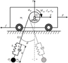 |
Fig. 2 Dynamic model of trolley-grab system with elastic wire rope. |
3 Improved NZV input shaper
For a second-order harmonic oscillation system, if its natural frequency is ω and damping ratio is ζ, then the constraint of residual vibration amplitude can be expressed as the ratio of the residual vibration amplitude of the system response with shaping input to that without shaping input, namely [5] (14)where,
 (15)
(15)
 (16)in which Ai and ti are the amplitudes and time locations of the impulses, respectively, and n is the number of impulses.
The NZV shaper is to add a negative pulse to the ZV shaper containing only two positive pulses. Compared with the ZV shaper, the NZV shaper parameters need to be satisfied by the following constraint equations [10] (17)
(17)
From equation (17), one can get (18)
(18)
But the solution of pulse delay would be complex and difficult, especially when the damping ratio ζ is not zero. In order to prevent the high frequency mode of the system with high P value [9], let P = 1, and the parameters of the NZV shaper can be obtained as (19)
(19)
The NZV shaper control method uses the acceleration of the trolley as the input signal that is convoluted with the shaper impulses to control the swinging of the grab. Take the acceleration of the trolley be  , and the result after the convolution be
  , Then the convolution equation of the acceleration and the shaper pulse is as follows
 (20)where, f(t) is a time-domain expression of shaper impulses. Namely,
 (21)
(21)
Substituting equation (21) into equation (20), one can get (22)
(22)
Assuming that the grab's swing angle is small, sin θ ≈ θ, cos θ ≈ 1. Then the second differential equation about the swing angle θ in equation (13) can be simplified as (23)
(23)
Therefore, the natural frequency and the damping ratio of the system can be obtained by (24)
(24)
The running path of the grab ship unloader includes the L-shaped path and the arc-shaped path [24]. When the grab moves along the L-shaped path, the rope length does not change, which means the natural frequency of the system is fixed and the damping ratio is zero. In this way, it is easy to obtain the NZV shaper parameters and determine the shaped acceleration of the trolley to control the swing angle of the grab.
If the grab ship unloader operates along an arc path, apparently, it can be seen from equation (24) that the natural frequency and damping ratio will change with the rope length. Here, two certain values in the frequency change range and the damping ratio change range are respectively taken as the equivalent frequency ωe and the equivalent damping ratio ζe, namely (25)
(25)
 (26)where, ωmax, ωmin, ζmax, and ζmin are maximal frequency, minimal frequency, maximal damping ratio and minimal damping ratio, respectively. The values of them are determined by l and
  in terms of equation (24).
The traditional NZV method usually uses the average rope length to design the shaper for the variable rope length crane system, but it does not achieve the best anti-sway effect. In this paper, an improved NZV method using equivalent frequency and equivalent damping ratio is proposed according to the following steps.
-
Preset a limit value of the residual swing angle θe, and then calculate the maximum frequency, the minimum frequency, the maximum damping ratio and the minimum damping ratio according to the variation range of the rope length.
-
The eight intervals of equal length are divided between the minimum frequency and the maximum frequency, and the median values of the eight intervals are ω1, ω2, …, and ω8, respectively. Similarly, the eight intervals of equal length are divided between the minimum damping ratio and the maximum damping ratio, and the median values of the eight intervals are ζ1, ζ2, …, and ζ8, respectively.
-
Design NZV shaper according to frequency ωi (i = 1, 2, …, 8) and damping ratio ζj (j = 1, 2, …, 8) and calculate the residual swing angle θij using fourth order Runge-Kutta method in terms of equation (13), respectively. Compare θij (i,j = 1, 2, …, 8), and get the minimum value θkl, and corresponding ωk, ζl.
-
Compare all the residual swing angles θij (i,j = 1, 2, …, 8), and select the minimal one θkl, and ωk, ζl.
-
If θkl ≤ θe, the equivalent frequency ωe is equal to ωk, and the equivalent damping ratio ζe is equal to ζl.
-
If θkl > θe, take the intervals of frequency ωk and damping ratio ζl as the calculation intervals, and return to step 2.
4 Case study
Taking an 800 t/h (800 tons per hour) grab ship unloader as an example, the numerical simulation analysis of the proposed method is carried out. The main parameters of the grab ship unloader are listed in Table 1.
Main parameters of a 800 t/h grab ship unloader.
4.1 Swing control simulation based on improved NZV shaper
According to equation (13),  and
and  can be expressed by
 (27)
(27)
In terms of equation (27), the Matlab/simulink module is used to construct the simulation model of the trolley-grab system. In the simulink model, the angular acceleration of lifting drum  and the trolley acceleration
  are the two inputs of system, in which the trolley acceleration
  is calculated by Matlab Function based on the improved NZV method. In addition, h, θ are the outputs of system, and l0, rhd, Δh, k1, mg, b1 are the adjustable parameters of system.
A typical operation status of the unloader is taken in the simulation, in which the trolley travel is 23 m, the initial rope length is 30 m, the shortest rope length is 8 m, and initial swing angle be 0 deg. The other parameters of the model are either obtained from the component manufacturers' catalogues, or approximately estimated with the rationality verified by the size and material of the apparatus. Here, the damping coefficient of the wire rope b1 is 220 N.s/m, the hoisting drum radius rhd is 0.168 m and the wire rope diameter d is 24 mm, and the stiffness coefficient of the hoisting rope k1 is 602880 N/m. The optimal control parameters are available according to the improved NZV method as shown in Table 2.
The improved NZV shaper is compared with the ZV and ZVD input shapers in which the control parameters are also optimized by the method proposed in this paper, and the command angular acceleration curves of the hoisting drum and the command acceleration curves of the trolley can be obtained under the different control methods as shown in Figure 3, and the corresponding velocity curves are as shown in Figure 4.
Figures 3 and 4 show that the time of a working cycle with NZV control method is similar to the ZV method, while the time of the working cycle with ZVD method is longer. This implies that the NZV method could improve the working efficiency of the ship unloader as it increases the negative impulses. Using the above command curves, one can obtain the grab swing angle curves as shown in Figure 5 based on the elastic wire rope model, and the maximum residual swing angles for the conditions of the full load and empty load under different control methods are shown in Table 3.
Figure 5 and Table 3 show that the NZV control scheme can reduce the working cycle time of the ship unloader about 11% compared to the ZVD control method when considering the elastic factor of the wire rope. Compared with the ZV control method, the maximum residual swing angle of grab with the NZV control method decreases by 67% when discharging at full load, and it decreases by 79% when taking the cargos at empty load. Therefore, when considering the elastic factor of the wire rope, the NZV control scheme can not only satisfy the swing angle control of the grab but also improve the working efficiency of the ship unloader.
Optimal control parameters.
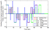 |
Fig. 3 Command angular acceleration curves of the hoisting drum and the command acceleration curves of the trolley under the different control methods. |
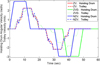 |
Fig. 4 Command angular velocity curves of the hoisting drum and the command velocity curves of the trolley under the different control methods. |
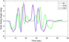 |
Fig. 5 Swing angle curves of the grab. |
Maximum residual swing angles for the conditions of the full load and empty load under different control methods.
4.2 Influences of elasticity factors
Comparing the traditional undamped system rigid rope model with the elastic wire rope model built in this paper, the oscillation curve of the grab along the hoisting rope direction and the length variation curves of the wire rope are shown in Figures 6 and 7, respectively.
It can be seen from Figures 6 and 7 that the oscillating value of the grab in the direction of the hoisting rope is zero when the rigid rope model is used, and the oscillating value in the direction of the hoisting rope using the elastic rope model has a high-frequency fluctuation, where the maximum fluctuation amplitude is about 20 mm.
Figure 8 is a comparison of the swing angles of the grab using improved NZV method. It can be seen that in the rigid rope model, the maximum residual swing angle is −0.5043 deg (22.66 s) in the full-load process, and the maximum residual swing angle is −0.1164 deg (46.89 s) in the empty-load process. In the elastic rope model, the maximum residual swing angle is −0.2550 deg (20.84 s) in the full-load process, and the maximum residual swing angle is −0.1143 deg (46.73 s) in the empty-load process. Compared to the rigid rope model, the maximum residual swing angle of grab in elastic rope model decreases by about 49% at most. Therefore, the model that considers the elastic factor can improve the swing angle control effect of grab based on the proposed control strategy.
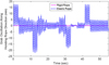 |
Fig. 6 Oscillation curve of grab in the direction of hoisting rope. |
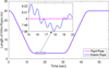 |
Fig. 7 Length variation curves of the wire rope. |
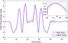 |
Fig. 8 Grab's swing angle curves in the case of a rigid wire rope and an elastic wire rope. |
4.3 Parameter sensitivity analysis of the maximum residual swing angle
Since the simulation analysis model may include modeling errors, it is necessary to analyze the sensitivity of the max remaining swing angle to the changes of some major design parameter. This section analyzes the sensitivity of parameters based on the elastic wire rope model using the improved NZV control method.
In practice, the center of grab's gravity may change when the grab loads and opens. Then, full load and empty load path should differ from the center of gravity of the grab, and it is often difficult to obtain the accurate value of damping coefficient. Therefore, it is necessary to compare the sensitivities of the maximum residual swing angle of the grab to the deviation of the grab's center of gravity along the direction of hoisting rope that may be caused by modeling errors by using the ZV, ZVD and NZV methods. Take the shortest length of wire rope of 8m whose deviation in the range of [–2 m, 2 m]. Then, under different control schemes, the curves of the maximum residual swing angle at full load and empty load with the deviation of the grab's center of gravity along the rope direction are shown in Figure 9.
In Figure 9, the maximum residual swing angles all increase with the increasing deviation of the grab's center of gravity under the different control method. The maximum residual swing angles of grab of full load path and empty load path reach 9.3119 deg and 4.7316 deg, respectively, especially under the NZV method, when the deviation of center of grab's gravity is −2 m. Therefore, the maximum residual swing angles of the grab under the different control method are all sensitive to the deviation of the center of gravity of the grab in the rope direction. Compared to the ZVD method, it is more sensitive under the NZV method. In the actual control system, the position of the grab's center of gravity should be as accurate as possible.
The stiffness coefficient of wire rope may also have large deviations when modeling. The stiffness coefficient of wire rope mainly depends on its elasticity modulus, cross sectional area and length of winding system. Since the stiffness coefficient is assumed to be a constant at a certain length, here the elastic modulus value and the calculated wire rope diameter value can be considered to have deviations during modeling. Take the wire rope diameter of 24 mm whose deviation in the range of [–4 mm, 4 mm], and the elastic modulus of the wire rope is 100 Gpa whose deviation in the range of [–10 Gpa, 10 Gpa]. Then the curves of grab's maximum residual swing angle varied with the deviations of the wire rope diameter and the elastic modulus are shown in Figure 10 during full load process. The empty load situation is shown in Figure 11.
From Figures 10 and 11, one can find that the maximum residual swing angle curve of the grab under different elastic modulus is approximately a straight line when the diameter of the wire rope is constant, and the maximum residual swing angle curve under different wire rope diameters is more obvious when the elastic modulus is constant. Therefore, compared to the elastic modulus deviation, the maximum residual swing angle is more sensitive to the wire rope diameter deviation.
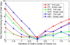 |
Fig. 9 Maximum residual swing angle curves with the deviation of the grab's center of gravity along the rope direction. |
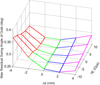 |
Fig. 10 Curves of maximum residual swing angle varied with the deviations of the wire rope diameter and the elastic modulus during full load process. |
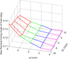 |
Fig. 11 Curves of maximum residual swing angle varied with the deviations of the wire rope diameter and the elastic modulus during empty load process. |
5 Conclusions
This paper proposes an improved NZV input shaper with the optimal control parameters of the variable rope length to improve swing control precision and the efficiency of bridge type grab ship unloader. Considering the elastic factor of the wire rope, a dynamical model of the trolley-grab system of grab ship unloader is established. Then, the numerical simulation model of the trolley-grab system is built through the MATLAB/Simulink module. Based on the numerical simulation model, the control effects, influences of elasticity factor and parameter sensitivities of the improved NZV input shaper are analyzed. Simulation results show that compared with the ZV and ZVD control methods, the improved NZV control method can reduce about 11% working cycle time of the grab ship unloader when considering the elastic factor wire rope. Meanwhile, the maximum residual swing angle of grab decreases by 67% when discharging at full load, and decreases by 79% when taking the cargos at empty load. This means that the improved NZV control method can not only improve the working efficiency of the grab ship unloader, but also achieve the better control effect of swing angle of the grab. Moreover, compared to the rigid rope model, the model that considers the elastic factor can improve the swing angle control effect of grab based on the proposed control strategy, and the elastic factor should not be ignored in the high precision control system. Furthermore, the maximum residual swing angle of grab is sensitive to the gravity center deviation of the grab, which indicates the position of the center of gravity of the grab should be as accurate as possible in the actual control system. In addition, compared to the elastic modulus deviation, the maximum residual swing angle of the grab is more sensitive to the wire rope diameter deviation. In the future research, the swing control strategy of the grab should consider the influence of the grab's opening/closing state. Meanwhile, the theoretical mathematical model should also consider the size and shape of grab, 3D systems with unpredictable loads such as wind forces and other intrinsic unbalanced forces, and an actual 3D industrial system or experiment should be considered to verify the applicability of the proposed control strategy.
Acknowledgments
This work was financially supported by National Key Research and Development Program of China (Grant No. 2019YFB1600400).
References
- W. Singhose, Command shaping for flexible systems: a review of the first 50 years, Int. J. Precis. Eng. Man. 10, 153–168 (2009) [CrossRef] [Google Scholar]
- O.J.M. Smith, Posicast control of damped oscillatory systems, Proc. IRE, 45, 1249–1255 (1957) [CrossRef] [Google Scholar]
- N.C. Singer, W.P. Seering, Preshaping command inputs to reduce system vibration, J. Dyn. Syst-T. ASME 112, 76–82 (1990) [CrossRef] [Google Scholar]
- W. Singhose, S. Derezinski, N. Singer, Extra-insensitive shapers for controlling flexible spacecraft, J. Guid. Control Dyn. 19, 385–391 (1996) [CrossRef] [Google Scholar]
- W. Singhose, W. Seering, N. Singer, Input shaping for vibration reduction with specified insensitivity to modeling errors, Jpn. USA Sym. Flexible Autom. 1, 307–313 (1996) [Google Scholar]
- W. Singhose, L. Pao, A comparison of input shaping and time-optimal flexible-body control, Control Eng. Pract. 5, 459–467 (1997) [CrossRef] [Google Scholar]
- J. Vaughan, A. Yano, W. Singhose, Comparison of robust input shapers, J. Sound Vib. 315, 797–815 (2008) [CrossRef] [Google Scholar]
- J. Vaughan, A. Yano, W. Singhose, Performance comparison of robust negative input shapers, in 2008 American Control Conference, Seattle, USA, 2008 [Google Scholar]
- W. Singhose, N. Singer, W. Seering, Design and implementation of time-optimal negative input shapers, in1994 International Mechanical Engineering Congress and Exposition, Chicago, USA, 1994 [Google Scholar]
- W. Singhose, N. Singer, W. Seering, Time-optimal negative input shapers, J. Dyn Syst-T. ASME 119, 198–205 (1997) [CrossRef] [Google Scholar]
- K. Sorensen, A. Daftari, W. Singhose, K. Hekman, Negative input shaping: eliminating overcurrenting and maximizing the command space, J. Dyn. Syst-T. ASME 130, 061012 (2008) [CrossRef] [Google Scholar]
- J. Vaughan, A. Yano, W. Singhose, Robust negative input shapers for vibration suppression, J. Dyn. Syst-T. ASME 131, 031014 (2009) [CrossRef] [MathSciNet] [Google Scholar]
- N. Singer, W. Singhose, E. Kriikku, An input shaping controller enabling cranes to move without sway, in 7th topical meeting on robotics and remote systems in ANS, Georgia, USA, 1997 [Google Scholar]
- W. Singhose, L. Porter, W. Seering, Input shaped control of a planar gantry crane with hoisting, in1997 American Control Conference, New Mexico, USA, 1997 [Google Scholar]
- W. Singhose, L. Porter, M. Kenison, E. Kriikku, Effects of hoisting on the input shaping control of gantry cranes, Control Eng. Pract. 8, 1159–1165 (2000) [CrossRef] [Google Scholar]
- K.T. Hong, C.D. Huh, K.S. Hong, Command shaping control for limiting the transient sway angle of crane systems, Int. J. Control Autom. 1, 43–53 (2003) [Google Scholar]
- K.L. Sorensen, W. Singhose, S. Dickerson, A controller enabling precise positioning and sway reduction in bridge and gantry cranes, Control Eng. Pract. 15, 825–837 (2007) [CrossRef] [Google Scholar]
- J. Stergiopoulos, A. Tzes, An adaptive input shaping technique for the suppression of payload swing in three-dimensional overhead cranes with hoisting mechanism, in 12th IEEE International Conference on Emerging Technologies and Factory Automation, Patras, Greece, 2007 [Google Scholar]
- S. Garrido, M. Abderrahim, A. Giménez, R. Diez, C. Balaguer, Anti-swinging input shaping control of an automatic construction crane, IEEE Trans. Autom. Sci. Eng. 5, 549–557 (2008) [CrossRef] [Google Scholar]
- Q.H. Ngo, Y. Nan, K.S. Hong, Command shaping for vibration reduction of container cranes, in 12th IEEE International Conference on control, Automation and Systems, Jeju Island, Korea, 2012 [Google Scholar]
- J.M. Veciana, S. Cardona, Residual vibration reduction in low damping systems, generation of regular piecewise algebraic polynomial inputs, J. Vibroeng. 13, 739–754 (2011) [Google Scholar]
- J.M. Veciana, S. Cardona, Residual vibration reduction in mechanical systems: a time-domain approach, Int. J. Precis. Eng. Man. 13, 1327–1339 (2012) [CrossRef] [Google Scholar]
- J.M. Veciana, S. Cardona, P. Català, Minimizing residual vibrations for non-zero initial states: Application to an emergency stop of a crane, Int. J. Precis. Eng. Man. 14, 1901–1908 (2013) [CrossRef] [Google Scholar]
- Y. Zhou, X. Zhang, Z. Yu, D. Schott, G. Lodewijks, An improved zero vibration method and parameter sensitivity analysis for the swing control of bridge-type grab ship unloader, Proc. Inst. Mech. Eng. C-J. Mec. 230, 2463–2472 (2016) [CrossRef] [Google Scholar]
- S. Arabasi, Z. Masoud, Simultaneous travel and hoist maneuver input shaping control using frequency modulation, Shock Vib. 1, 1–12 (2017) [Google Scholar]
- M.J. Maghsoudi, Z. Mohamed, S. Sudin, S. Buyamin, H.I. Jaafar, S.M. Ahmad, An improved input shaping design for an efficient sway control of a nonlinear 3D overhead crane with friction, Mech. Syst. Signal Process. 92, 364–378 (2017) [CrossRef] [Google Scholar]
- A.M. Abdullahi, Z. Mohamed, H. Selamat, H.R. Pota, M.Z. Abidin, F.S. Ismail, A. Haruna, Adaptive output-based command shaping for sway control of a 3D overhead crane with payload hoisting and wind disturbance, Mech. Syst. Signal Process. 98, 157–172 (2018) [CrossRef] [Google Scholar]
- L. Ramli, Z. Mohamed, H.I. Jaafar. A neural network-based input shaping for swing suppression of an overhead crane under payload hoisting and mass variations, Mech. Syst. Signal Process. 107, 484–501 (2018) [CrossRef] [Google Scholar]
- W. Singhose, S. Towell, Double-pendulum gantry crane dynamics and control, in 1998 IEEE International Conference on Control Applications, Atlanta, USA, 1998 [Google Scholar]
- W. Singhose, M. Kenison, D. Kim, Input shaping control of double-pendulum bridge crane oscillations, J. Dyn. Syst. Trans. ASME 130, 034504 (2008) [CrossRef] [Google Scholar]
- D. Kim, W. Singhose, Performance studies of human operators driving double-pendulum bridge cranes, Control Eng. Pract. 18, 567–576 (2010) [CrossRef] [Google Scholar]
- J. Vaughan, D. Kim, W. Singhose, Control of tower cranes with double-pendulum payload dynamics, IEEE Trans. Control Syst. T. 18, 1345–1358 (2010) [Google Scholar]
- Z. Masoud, K. Alhazza, E. Abu-Nada, M. Majeed, A hybrid command-shaper for double-pendulum overhead cranes, J. Vib. Control 20, 24–37 (2012) [Google Scholar]
- Z. Masoud, K. Alhazza, Frequency-modulation input shaping control of double-pendulum overhead cranes, J. Dyn. Syst-T. ASME 136, 21005 (2014) [CrossRef] [Google Scholar]
- Z. Masoud, K. Alhazza, E. Abu-Nada, M. Majeed, A hybrid command-shaper for double-pendulum overhead cranes, J. Vib. Control 20, 24–37 (2014) [CrossRef] [Google Scholar]
Cite this article as: X. Cao, C. Meng, Y. Zhou, M. Zhu, An improved negative zero vibration anti-swing control strategy for grab ship unloader based on elastic wire rope model, Mechanics & Industry 22, 45 (2021)
All Tables
Maximum residual swing angles for the conditions of the full load and empty load under different control methods.
All Figures
|
Fig. 1 3D model of a grab ship unloader. |
| In the text | |
|
Fig. 2 Dynamic model of trolley-grab system with elastic wire rope. |
| In the text | |
|
Fig. 3 Command angular acceleration curves of the hoisting drum and the command acceleration curves of the trolley under the different control methods. |
| In the text | |
|
Fig. 4 Command angular velocity curves of the hoisting drum and the command velocity curves of the trolley under the different control methods. |
| In the text | |
|
Fig. 5 Swing angle curves of the grab. |
| In the text | |
|
Fig. 6 Oscillation curve of grab in the direction of hoisting rope. |
| In the text | |
|
Fig. 7 Length variation curves of the wire rope. |
| In the text | |
|
Fig. 8 Grab's swing angle curves in the case of a rigid wire rope and an elastic wire rope. |
| In the text | |
|
Fig. 9 Maximum residual swing angle curves with the deviation of the grab's center of gravity along the rope direction. |
| In the text | |
|
Fig. 10 Curves of maximum residual swing angle varied with the deviations of the wire rope diameter and the elastic modulus during full load process. |
| In the text | |
|
Fig. 11 Curves of maximum residual swing angle varied with the deviations of the wire rope diameter and the elastic modulus during empty load process. |
| In the text | |
Current usage metrics show cumulative count of Article Views (full-text article views including HTML views, PDF and ePub downloads, according to the available data) and Abstracts Views on Vision4Press platform.
Data correspond to usage on the plateform after 2015. The current usage metrics is available 48-96 hours after online publication and is updated daily on week days.
Initial download of the metrics may take a while.