| Issue |
Mechanics & Industry
Volume 23, 2022
|
|
|---|---|---|
| Article Number | 4 | |
| Number of page(s) | 10 | |
| DOI | https://doi.org/10.1051/meca/2022004 | |
| Published online | 17 February 2022 | |
Regular Article
Shear buckling of ship plates with different holes
1
School of Marine Engineering, Jimei University, Xiamen 361021, China
2
Fujian Provincial Key Laboratory for Naval Architecture and Ocean Engineering, Xiamen 361021, China
* e-mail: This email address is being protected from spambots. You need JavaScript enabled to view it.
Received:
2
July
2021
Accepted:
14
January
2022
Abstract
Based on the first-order shear deformation theory, numerical methods and mechanical experiments, the shear buckling characteristics of hull plates with different holes are investigated. Through eigenvalue buckling analysis, the critical buckling stress of square plate with hole under uniform shear load on four edges was calculated. The relationship between the critical shear stress and the hole type, hole size and plate thickness was obtained by parameterization. The reduction coefficient (ki) was defined to characterize the effect of the hole on the plate, and the reduction effect of circular hole, square hole and fillet square hole was simplified by graph and fitting polynomial. The results show that the critical buckling shear stress obtained from numerical simulation is in good agreement with the experimental value. For different types of holes, the critical buckling shear stress of the square plate has the same trend with the plate thickness. Both plate thickness and hole size have great influence on the shear stability of the perforated square plate. When the hole size is constant, the critical shear stress increases with the increase of plate thickness. The smaller the hole size is, the greater the influence of plate thickness. The critical shear stress decreases with the increase of hole size, and there is a similar linear relationship. The smaller the plate thickness, the more obvious the linear relationship. In addition, based on the reduction coefficient curve or fitting polynomial proposed in this paper, the influence rules of the three different holes on the shear stability of hull plates can be obtained quickly and effectively, thus providing a useful reference for the design optimization and mechanical property evaluation of ship structures with holes.
Key words: shear buckling / stability / reduction factor / hole / hull structure
© Z. Zhu et al., Published by EDP Sciences 2022
 This is an Open Access article distributed under the terms of the Creative Commons Attribution License (https://creativecommons.org/licenses/by/4.0), which permits unrestricted use, distribution, and reproduction in any medium, provided the original work is properly cited.
1 Introduction
In order to meet the needs of economic efficiency, structural efficiency, function and aesthetics, perforated plates are widely used in various engineering structures such as ships, aviation and civil engineering. Especially for large passenger ships, luxury cruise, etc., with multi-layer continuous superstructure, thin wall panels, side panels and longitudinal bulkheads are provided with different forms of holes. There are a large number of holes in these hull. However, due to the existence of holes, the stability and carrying capacity of the plates are affected, and the safety of the whole ship structure is greatly threatened. Therefore, it is very important to study the influence of holes on the stability of the ship plates [1].
For a long time, the stability of the plate plays a very important role in the design and strength check of the ship structure [2,3]. A large number of marine accidents show that the damage of ship structure is usually caused by the loss of stability rather than the lack of strength. When the longitudinal bending of the hull occurs, the deck panels, side panels and the bottom plate of the ship are subject to longitudinal forces, and there is a possibility of instability. Especially for the plates under greater pressure and shear force, stability problem must be considered. Side plate is the main component of shear resistance and must meet the requirements of shear stability. With the increasing of the ship's volume and the scale of superstructure, the number and size of the holes in the side structure increase correspondingly. The stability and safety of side plate with holes for large ships are becoming more and more prominent.
The stability of thin-walled structures has always been a hot issue at home and abroad [4–6]. Previous studies focused on the buckling and post-buckling of stiffened plates without holes. In terms of the stability of perforated thin plates, Eccher et al. [7] used the finite-strip method to study the elastic buckling of perforated plates and folded plates. Based on finite element software, Moen et al. [8] studied the elastic buckling problem of rectangular perforated plates under unidirectional compression and bending loads, and proposed some simplified expressions. In the literature [9], a semi-analytical method for solving the stability of the plate with a hole was proposed. Abaqus software was used to calculate the ultimate strength of hull plate under axial pressure in the literature [10]. The literature [11] analyzed the elastic buckling and post-buckling behaviors of unstiffened plates under complex stress states, and compared them with empirical formulas and ABS specifications. Peridynamics was applied to the analysis of axial compression stability of metal plates in the literature [12]. Galerkin method was used to solve the elastic-plastic buckling problem of rectangular plates under shear stress in literature [13]. The buckling problem of anisotropic rectangular plates under shear stress was analyzed by differential quadrature method in literature [14]. The differential equation of lateral displacement function of rectangular thin plate under shear buckling was established in literature [15], and the analytical solution of the critical buckling load of rectangular thin plate was obtained. Paik [16] studied the ultimate strength of perforated steel plate under edge shear load, and obtained an empirical formula to predict the maximum tensile strength of perforated plate. Pham [17] used the finite strip method to study the shear buckling of the plate with a hole, and proposed an approximate formula for the shear buckling coefficient of a square plate with a central circular hole and a square hole.
Local rectangular thin-wall plates subjected to shear force are widely used in engineering structures such as ships and buildings. The buckling instability of local plates has become one of the main forms of structural failure. Previous studies on the stability of perforated plates were mostly focused on a single perforated type, and the loading conditions were mainly tensile, compression and bending. For the buckling instability of local rectangular plate under shear stress, analytical method and finite element method are mainly used. The calculation of the analytical method is cumbersome, and the finite element simulation can avoid the tedious calculation program of the buckling analysis, but the calculation accuracy is limited to the design accuracy of the model and boundary conditions [18,19].
In the actual design process, compared with analytical derivation and finite element simulation, empirical formulas or graphs are more practical and more efficient. Therefore, this paper focuses on the buckling characteristics of ship's plates with different holes under in-plane shear loading by means of the first-order shear deformation theory, mechanical experiments and numerical simulation. In the numerical simulation, eigenvalue analysis method was used to study the buckling behavior of the perforated plates. In order to verify the effectiveness of the numerical method, the picture frame fixture was used to conduct the shear test on the perforated plates. In addition, the response rules of the hole type, hole size and plate thickness to the buckling characteristics of hull plates are obtained. The reduction factor of perforated plates is defined and analyzed. The empirical graph and the fitting polynomial are established to characterize the reduction effect of the hole of the plate, which can quickly obtain the buckling critical shear stress of the square plate with a round hole, square hole and fillet square hole. These will provide a useful reference for the shear stability analysis and design optimization of the ship structure with holes.
2 Theoretical method
2.1 Basic equation
2.1.1 Displacement field
In Mindlin's first-order shear deformed plate theory, it is assumed that the normal strain of the plate along the thickness direction is zero, and that the normal line perpendicular to the middle plane is still a straight line after deformation, but it does not remain a normal line. In this case, the displacement of plate element can be expressed as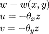 (1)where w, u and v are displacements in x, y and z directions; Z is the distance from any point of the plate to the neutral plane along the thickness direction. θx, θy are the rotation angles of the middle plane of the plate around the y and x axes. It is assumed that there is no internal displacement in the midplane, for the shear-deformed plate, there is
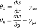 (2)where γxz and γyz are angular strains caused by transverse shear deformation.
2.1.2 Physical equation
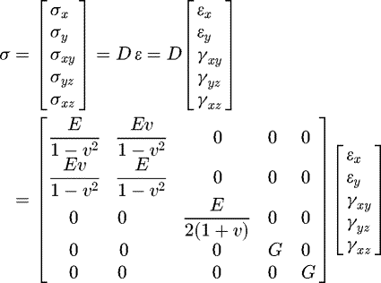 (3)
(3)
where σx, σy and σxy are the in-plane normal stress and shear stress, respectively; σyz and σxz are transverse shear stress; D is the stiffness matrix; εx, εy and γxy are the in-plane linear strain and angular strain, respectively; E is the elastic modulus; G is the shear elasticity modulus; ν is Poisson's ratio.
The displacement function of the first-order shear deformation theory is easy to meet the rigid body displacement conditions, constant strain conditions and continuity requirements, and it is easy to approximate curved edges and curved surfaces with small geometric errors; It can be used for both linear and nonlinear calculation of plates. This theory can be applied to most practical situations with higher accuracy.
2.2 Eigenvalue equation
Linear buckling is also called eigenvalue buckling analysis, and the corresponding buckling load can be determined by the following linear generalized eigenvalue equation [20].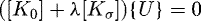 (4)where [K0] is the linear stiffness matrix of the structure; [Kσ] is the geometric stiffness matrix of the structure; λ is the load scaling factor; {U} is the lateral displacement vector. It can be seen from equation (4) that the linear stability problem of the structure is the eigenvalue problem, and the corresponding critical load and instability mode can be obtained by solving the eigenvalue and eigenvector.
3 Physical model
3.1 Geometric model
Under the condition that the lighting area remains unchanged, Three typical perforated plates are designed, as shown in Figure 1. The dimensional parameters and material properties are shown in Table 1.
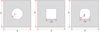 |
Fig. 1 Dimensional parameters of the perforated plate on the side. |
Geometric dimensions and material properties of the perforated plate.
3.2 Load condition
Side plates are the main components of shear resistance, which must meet the requirements of shear stability, especially the perforated plate on the side. In general, the boundary of hull plates is supported by beam members (such as stiffeners), and the bending stiffness of boundary support elements is much larger than that of plates, which means that the displacement of support elements along the direction of plate deformation is very small. Even if the plate elements fail, the displacement of support elements is also very small. Generally, in the study of buckling strength, it is necessary to consider the influence of torsional constraints of the support elements on the plate. For this reason, based on the perforated plates on the side of the superstructure of a large ship, a load condition of simply supported on four edges with limited torsion and uniformly distributed shear stress is designed (Fig. 2).
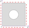 |
Fig. 2 Schematic diagram of shear condition of the perforated plate (taking circular perforated plate as an example). |
4 Numerical method
Based on the Abaqus, the finite element model of the ship's side perforated plate was established, as shown in Figure 3. The plane continuous shell element S4R was used to discretization the model. The S4R is a 4-node first order reduction integral element, which uses linear interpolation method, allows finite film strain and large rotation angle, considers the influence of shear deformation, and is suitable for geometrical and material nonlinear analysis. As shown in Figure 3, hinge connection units were used at the circular shaft holes at A, B, C and D to simulate the effect of pins. The tie binding constraints were set at the picture frame fixture and the four edges of the specimen to simulate bolt connection. Point C was set as the fixed point. Point A was defined as the loading point, and a vertical upward force F was applied. The force F is decomposed into Nxy along the direction of the fixture. The specimen was compressed in the direction of AC and pulled in the direction of BD. Under the action of binding constraints, the test plate was subjected to shear load. The eigenvalue buckling analysis was completed by Abaqus. The buckling modes of the square plate with circular hole and fillet square hole were obtained (shown in Fig. 4), and the critical buckling shear stresses of the two perforated square plates were calculated to be 12.14 MPa and 11.41 MPa, respectively.
In order to verify the accuracy of the simulation results, the shear tests of the above perforated plates were carried out with the help of WDW100-100C electronic universal testing machine and the picture frame fixture, as shown in Figure 5. The specimens are made of ordinary marine steel, and the material properties are shown in Table 1. During the test, the maximum load was 100 kN and the continuous loading rate was 2 mm/min. The specimen was fully compressed by four sets of bolts, and the frame fixture was hinged to each other at the top. When the testing machine was loaded, the tension F was decomposed along the direction of the fixture, so that the specimen could bear the shear load.
Figure 6 indicates the load (F)-displacement (D) curves and the first order buckling cloud of the plates with different hole, and the where D represents the displacement of point A as shown in Figure 3. As can be seen from the graph, the position of critical buckling is not obvious. Therefore, a 3D full-field strain measurement and analysis system was used to determine the critical buckling point. Based on the full-field displacement cloud, the buckling time of the perforated plates was obtained, that is, ① and ② as shown in Figure 6.
The critical buckling stresses of the perforated plates got by the shear test are 12.53 MPa and 11.88 MPa, respectively. For critical buckling stress, the corresponding errors between the numerical simulation and the test results are 3.11% and 3.96% respectively. Therefore, the numerical method presented in this paper can effectively predict the critical buckling stress of the perforated plates under the condition of shear instability.
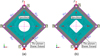 |
Fig. 3 Finite element models of square plates with different holes. (a) Square plate with circular hole. (b) Square plate with fillet square hole. |
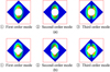 |
Fig. 4 Buckling modes of square plates with different holes. (a) Square plate with circular hole. (b) Square plate with fillet square hole. |
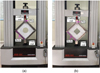 |
Fig. 5 Shear buckling tests of square plates with different holes. (a) Square plate with circular hole. (b) Square plate with fillet square hole. |
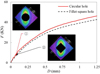 |
Fig. 6 Force versus displacement of plates with different hole. |
5 Shear stability analysis of perforated plates
The holes of hull plates are mostly circular, square and fillet square hole. The eigenvalue buckling analysis of the perforated plates with different variable parameters was carried out based on the finite element analysis software Abaqus. And the relationship between critical buckling stress and geometrical parameters of the perforated plates under uniform shear force on four edges is obtained.
5.1 Critical shear stress
Figure 7 shows the buckling characteristics of square plate with circular hole. The horizontal axis is the ratio of the circular hole radius r to the plate length b, and the longitudinal axis is the ratio of the critical buckling shear stress τcr to the shear yield stress τy. In this figure, the relationship between the critical buckling shear stress τcr and the hole radius r and the plate thickness t is presented in the dimensionless form. Corresponding to different (t/b)2, the τcr decreases with the increase of the hole relative size r/b. The bigger the hole size is, the greater the influence of plate thickness t on τcr. When the relative scale r/b of the circular hole is constant, the critical buckling shear stress τcr increases with the increase of (t/b)2, and the degree of this increase is more obvious with the increasing of plate thickness. However, it is not economical to improve the stability of plates by increasing the plate thickness.
Figure 8 shows the relationship between the plate critical stress τcr and thickness t, the size of the hole a under the condition of shear buckling. Analyzing the curves in Figure 8, it is found that although the type and size of the circular hole and square hole are different, the curves of critical shear stress are consistent with the plate thickness and square hole size. However, different holes and plate thicknesses have different effects on the critical buckling shear stress. As shown in Figure 9, under a certain plate thickness, the degree of influence of hole size on τcr is that circular hole > fillet square hole > square hole. When r/b = a/b = 0.2, the τcr of the plate with circular hole is 18% larger than that with square hole and 15% larger than that with fillet square hole. As shown in Figure 10, when the thickness and side length of the plate are constant, the τcr of the three types of perforated plates decreases with the increase of the hole's area (A). Corresponding to the same area of the hole, the influence of the hole's type on the τcr is similar, and the influence of the circular hole is slightly larger, followed by the fillet square hole, and the square hole has the least influence. Therefore, under the same working condition, circular hole is more suitable for shear condition. As shown in Figure 11, when the size of the hole is small, the hole type has little effect on τcr, regardless of the circular hole or the square hole, the τcr increases linearly with the increase of (t/b)2. However, when the size of the hole is large, the linear relationship between τcr and (t/b)2 is still keep, but the influence of the circular holes on τcr is greater than that of square holes. When r/b = a/b = 0.03, the τcr of the plate with circular hole is 18% larger than that with square hole; when r/b = a/b = 0.4 and (103t/b)2 = 225, the τcr of the plate with circular hole is 31% larger than that with square hole.
In order to further verify the consistency and validity of numerical results, two groups of linear relation curves of square perforated plate are obtained by dimensionless geometric variables in Figures 12 and 13. As shown in the two figures, when the hole size is constant, no matter the hole size is circular or square, the critical buckling shear stress of the plate has a linear relationship with the geometric parameter (t/b)2, which is consistent with the empirical formula [21]. It can be seen that the results in the figures are valid and corresponding to different (t/b)2, and the proportional relationship between the critical buckling shear stress τcr and shear yield stress τy can be obtained directly by reading these figures, which is simple and quick, and has a certain universality.
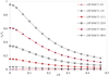 |
Fig. 7 Buckling of square plates with circular holes. |
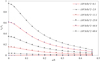 |
Fig. 8 Buckling of square plates with square holes. |
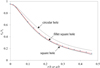 |
Fig. 9 The influence of hole's shape on critical stress (t = 2.5 mm). |
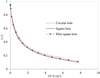 |
Fig. 10 The influence of the hole's area on critical stress (t = 2.5 mm, b = 300 mm). |
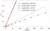 |
Fig. 11 The influence of plate thickness on critical stress. |
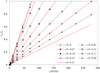 |
Fig. 12 The linear relation curves of square plates with circular holes. |
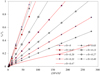 |
Fig. 13 The linear relation curves of square plates with square holes. |
5.2 Hole reduction coefficient
For a rectangular plate simply supported on four edges and with limited torsion, when the four edges are subjected to uniform shear forces, the critical buckling shear stress can be obtained by the following equation [21]: (5)where k0 is the shear buckling coefficient and is a function of the length-width ratio of the rectangular plate. When the length and width of the plate are equal, k0=15; t is the plate thickness; b is the width of the plate.
Considering the influence of different hole types and sizes, the elastic buckling shear stress formula of the perforated plate under the shear condition as shown in Figure 2 can be expressed as the following (6)where ki is the hole reduction coefficient. And i =1 represents the circular hole; i = 2 represents the square hole; i = 3 represents the fillet square hole.
It can be seen from equation (6) that how to determine the hole reduction coefficient ki is the key to obtain the critical buckling shear stress of perforated plates. Therefore, based on the numerical analysis results in Section 4.1, the hole reduction coefficient curves are drawn according to the type and size of the hole, as shown in Figures 14 and 15. As can be seen from the figures, whether the hole is circular or square, the variation trend of ki (i = 1, 2) is consistent with the dimensionless geometric parameters (r/b or a/b). That is, the hole reduction coefficient ki decreases with the increases of the hole size, and the larger the hole size, the more gentle the decreasing trend.
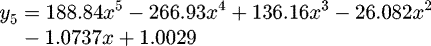
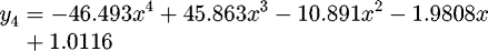
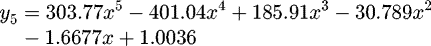
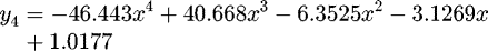
In order to effectively get the reduction coefficient values of perforated plates with different holes, the reduction coefficient curves in Figures 14 and 15 were fitted by the least square method, and the fitting polynomial was obtained. Let x = a/b and y = k1, then the reduction coefficient k1 of square plate with circular hole can be fitted by the following polynomials (7)–(10).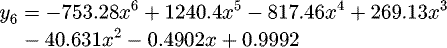 (7)
(7)
 (8)
(8)
 (9)
(9)
 (10)with the increase of the power exponent of the polynomial, the accuracy of the fitting curve is continuously improved. When y is a sixth degree polynomial, the fitting curve almost coincides with k1 curve. Figure 16 shows the closeness between the fitting polynomial with different power exponents (y3-6)and the reduction coefficient k1 for different hole sizes. Figure 17 shows the errors of the reduction coefficient with the power exponent of the fitting polynomial at different hole sizes. It can be seen that the order of fitting accuracy of the polynomial of the reduction coefficient k1 is y6>y5>y4>y3.
In the same way, let x = a/b and y = k2, then the reduction coefficient k2 of the square plate with square hole can be fitted into the following polynomial form: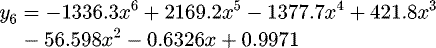 (11)
(11)
 (12)
(12)
 (13)
(13)
 (14)
(14)
The fitting condition of reduction factor k2 is similar to that of k1. Figure 18 shows the closeness between y and k1 for different hole sizes. And Figure 19 shows the errors of the reduction coefficient with the power exponent of the fitting polynomial at different hole sizes. The order of the fitting accuracy of k2 is also y6>y5>y4>y3.
In the practical application of ships, square plates with square hole often require chamfering to reduce stress concentration. However, the relationship between critical buckling shear stress and geometric parameters after chamfering is more complex. And it is difficult to obtain a uniform change rule with the change of hole size and fillet radius. There are also few previous related studies. In this paper, the relationship between the hole reduction coefficient k3 and geometric parameters in the plate with fillet square hole is described in the form of graph. As shown in Figure 20, in order to make this graph applicable to perforated plates of different materials, the vertical axis is defined as the product of the reduction factor k3 and the elastic modulus E. In the figure, square hole and circular hole are the two limit states of the fillet square hole. When the hole size is constant, k3 increases with the increase of the fillet radius R, but R has little influence on k3; When the fillet radius is constant, k3 decreases with the increase of the hole size. The relationships are consistent with that of square plate with circular hole and square hole. By referring to this graph, k3E can be obtained directly. Then, based on the simplified formula (6) proposed in this paper, the critical buckling shear stress of the square plate with fillet square holes can be quickly obtained.
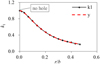 |
Fig. 14 Reduction coefficient k1 of square plate with circular hole. |
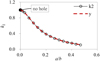 |
Fig. 15 Reduction coefficient k2 of square plate with square hole. |
 |
Fig. 16 The fitting reduction coefficient k1 of the square plate with circular hole. |
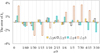 |
Fig. 17 The errors of the reduction coefficient k1 of the square plate with circular hole. |
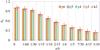 |
Fig. 18 The fitting reduction coefficient k1 of the square plate with square hole. |
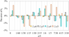 |
Fig. 19 The errors of the reduction coefficient k2 of the square plate with square hole. |
 |
Fig. 20 The relationship between the reduction coefficient and the geometric parameters of the square plate with fillet square hole (t = 0.1 mm). |
6 Conclusions
In this paper, the shear buckling characteristics of ship perforated plates with circular hole, square hole and fillet square hole are studied by numerical simulation. The validity of the numerical simulation results of critical buckling shear stress is verified by theoretical analysis and mechanical experiment. By changing geometrical parameters such as hole size, plate thickness and hole type, a series of mechanical response relationships between critical shear stress and hole type, hole size and plate thickness were obtained. It is found that the critical buckling shear stress of the square plate has the same trend with the plate thickness, for different types of holes. Both plate thickness and hole size have great influence on the shear stability of the perforated square plate. When the hole size is constant, the critical shear stress increases with the increase of plate thickness. The smaller the hole size is, the greater the influence of plate thickness. The critical shear stress decreases with the increase of hole size, and there is a similar linear relationship. The smaller the plate thickness, the more obvious the linear relationship. Under a certain plate thickness, the degree of influence of hole size on τcr is that circular hole > fillet square hole > square hole; When the size of the hole is small, the hole's type has little effect on τcr. However, when the size of the hole is large, the influence of the circular hole on τcr is greater than that of square hole. Corresponding to the same area of the hole, the influence of the hole's type on the τcr is similar, and the influence of the circular hole is slightly larger, followed by the fillet square hole and the square hole. Therefore, under the same working condition, circular hole is more suitable for shear condition. In addition, the reduction coefficient (ki) was defined to characterize the effect of the hole on the plate. Based on the reduction coefficient curve and fitting polynomial proposed in this paper, the influence rules of these three type holes on the shear stability of hull plates can be obtained quickly and effectively, which provides a useful reference for designers to analyze the shear stability and structural optimization of open hole plate.
Acknowledgements
This work was financed by the National Natural Science Foundation of China (Grant No. 51909103), the Natural Science Foundation of Fujian Province (Grant No. 2021J01841) and the Project of Fujian Provincial Department of Education of China (Grant No. JAT200290).
References
- J.K. Paik, Ultimate strength of perforated steel plates under combined biaxial compression and edge shear loads, Steel Constr. 46, 207–213 (2008) [Google Scholar]
- C. Yanting, Y. Changli, G. Hongbin, Research development of buckling and ultimate strength of hull plate and stiffened panel, Chin. J. Ship Res. 1, 54–62 (2017) [Google Scholar]
- L. Xiaowen, Z. Zhaoyi, L. Yan et al., Research on buckling and post buckling behavior of composite stiffened panel for ships, Shipbuild. China 61, 186–194 (2020) [Google Scholar]
- W. Zhao, Z. Xie, X. Wang et al., Buckling behavior of stiffened composite panels with variable thickness skin under compression, Mech. Adv. Mater. Struct. 1–9 (2019) [Google Scholar]
- M.C. Xu, C.G. Soares, Numerical assessment of experiments on the ultimate strength of stiffened panels, Eng. Struct. 45 (2012) [Google Scholar]
- W. Jianzhong, H. Ying, C. Yanling et al., Shear buckling analysis for simply supported plate panel with larger opening, Shipbuild. Technol. 1, 27–30 (2012) [Google Scholar]
- G. Eccher, K. Rasmussen, R. Zandonini, Elastic buckling analysis of perforated thin-walled structures by the isoparametric spline finite strip method. Thin-Walled Struct. 46, 165–191 (2008) [CrossRef] [Google Scholar]
- C.D. Moen, B.W. Schafer, Elastic buckling of thin plates with holes in compression or bending, Thin-Walled Struct. 47, 1597–1607 (2009) [CrossRef] [Google Scholar]
- P. Zuxing, Semi-analytical methods for stress and stability analyses of perforated plates. Ph.D. Thesis, Huazhong University of Science and Technology, 2014 [Google Scholar]
- F. Liang, H. Jingke, S. Hongda et al., Influence factors and sensitivity analysis of numerical calculation of hull panel ultimate strength, Ship Sci. Technol. 39, 48–55 (2017) [Google Scholar]
- X. Jinsong, Q. Enrong, Ultimate Strength Analysis of unstiffened plates under Complex Stress, in: Proceedings of the 20th Anniversary Academic Conference in Commemoration of Ship Mechanics, 2017 [Google Scholar]
- S. Luyan, Stability analysis method study of metallic plates based on peridynamics. Master's Thesis, Shanghai Jiao Tong University, 2014 [Google Scholar]
- S. Renu, L. Roshan, Buckling and vibration of non-homogeneous orthotropic rectangular plates with variable thickness using DQM, Adv. Intell. Syst. Comput. 23, 295–304 (2014) [Google Scholar]
- E. Jaberzadeh, M. Azhari, Elastic and inelastic local buckling of rectangular plates subjected to shear force using the Galerkin method, Appl. Math. Modell. 33, 1874–1885 (2009) [CrossRef] [Google Scholar]
- Y. Duansheng, H. Yan, L. Guangli, Shear buckling analysis of anisotropic rectangular plates, Chin. J. Appl. Mech. 29, 221–224 (2012) [Google Scholar]
- J.K. Paik, Ultimate strength of perforated steel plates under edge shear loading, Thin-Walled Struct. 45, 301–306 (2007) [CrossRef] [Google Scholar]
- C.H. Pham, Shear buckling of plates and thin-walled channel sections with holes, J. Constr. Steel Res. 128, 800–811 (2017) [CrossRef] [Google Scholar]
- C. Yan, T. Fenglian, X. Zhigang, In-plane stress analysis of thin sheet with irregular shape, Mach. Des. Manufact. 8, 218–220 (2012) [Google Scholar]
- F. Wei-gang, Y. Feng, W. Hong et al., The buckling numerical analysis of rectangular plates under shear force, Mach. Des. Manufact. 8, 20–22+26 (2015) [Google Scholar]
- N.Z. Chen, C.G. Soares, Buckling analysis of stiffened composite panels, in: III European Conference on Computational Mechanics, Springer, Netherlands, 2006 [Google Scholar]
- L. Xiangdong, Ship structure and strength (Harbin Engineering University Press, 2010) [Google Scholar]
Cite this article as: Z. Zhu, X. Li, Q. Chen, Y. Cai, Shear buckling of ship plates with different holes, Mechanics & Industry 23, 4 (2022)
All Tables
All Figures
|
Fig. 1 Dimensional parameters of the perforated plate on the side. |
| In the text | |
|
Fig. 2 Schematic diagram of shear condition of the perforated plate (taking circular perforated plate as an example). |
| In the text | |
|
Fig. 3 Finite element models of square plates with different holes. (a) Square plate with circular hole. (b) Square plate with fillet square hole. |
| In the text | |
|
Fig. 4 Buckling modes of square plates with different holes. (a) Square plate with circular hole. (b) Square plate with fillet square hole. |
| In the text | |
|
Fig. 5 Shear buckling tests of square plates with different holes. (a) Square plate with circular hole. (b) Square plate with fillet square hole. |
| In the text | |
|
Fig. 6 Force versus displacement of plates with different hole. |
| In the text | |
|
Fig. 7 Buckling of square plates with circular holes. |
| In the text | |
|
Fig. 8 Buckling of square plates with square holes. |
| In the text | |
|
Fig. 9 The influence of hole's shape on critical stress (t = 2.5 mm). |
| In the text | |
|
Fig. 10 The influence of the hole's area on critical stress (t = 2.5 mm, b = 300 mm). |
| In the text | |
|
Fig. 11 The influence of plate thickness on critical stress. |
| In the text | |
|
Fig. 12 The linear relation curves of square plates with circular holes. |
| In the text | |
|
Fig. 13 The linear relation curves of square plates with square holes. |
| In the text | |
|
Fig. 14 Reduction coefficient k1 of square plate with circular hole. |
| In the text | |
|
Fig. 15 Reduction coefficient k2 of square plate with square hole. |
| In the text | |
|
Fig. 16 The fitting reduction coefficient k1 of the square plate with circular hole. |
| In the text | |
|
Fig. 17 The errors of the reduction coefficient k1 of the square plate with circular hole. |
| In the text | |
|
Fig. 18 The fitting reduction coefficient k1 of the square plate with square hole. |
| In the text | |
|
Fig. 19 The errors of the reduction coefficient k2 of the square plate with square hole. |
| In the text | |
|
Fig. 20 The relationship between the reduction coefficient and the geometric parameters of the square plate with fillet square hole (t = 0.1 mm). |
| In the text | |
Current usage metrics show cumulative count of Article Views (full-text article views including HTML views, PDF and ePub downloads, according to the available data) and Abstracts Views on Vision4Press platform.
Data correspond to usage on the plateform after 2015. The current usage metrics is available 48-96 hours after online publication and is updated daily on week days.
Initial download of the metrics may take a while.