| Issue |
Mechanics & Industry
Volume 27, 2026
|
|
|---|---|---|
| Article Number | 24 | |
| Number of page(s) | 13 | |
| DOI | https://doi.org/10.1051/meca/2026021 | |
| Published online | 01 June 2026 | |
Original Article
Development and validation of a thermal finite element simulation of a wheel bearing
1
NTN- Europe, FR-74000 Annecy, France
2
Université Savoie Mont Blanc, SYMME, FR-74000 Annecy, France
* e-mail: This email address is being protected from spambots. You need JavaScript enabled to view it.
Received:
3
February
2026
Accepted:
15
April
2026
Abstract
Rolling bearings operating at high rotational speeds are subject to frictional losses that generate significant self-heating and may affect performance and durability. Predicting temperature fields in sealed wheel bearing assemblies is therefore essential for design and thermal management. In this work, an experimentally calibrated thermo-mechanical finite element framework is developed to simulate the thermal behavior of complete third-generation wheel bearings, including rolling contacts, sealing interfaces, and the surrounding test bench environment. Heat generation is introduced from measured friction torque and distributed at the ball–raceway and seal–hub contacts, while conduction and convection mechanisms are implemented through dedicated thermal boundary conditions. Convective parameters are identified from controlled cooling tests. The model is validated using a dedicated bench equipped with dynamic torque and infrared thermography measurements. Simulations are assessed on two-wheel bearings with significantly different geometries, without any additional parameter recalibration. Predicted steady-state temperatures show good agreement with experiments, with deviations remaining below 3%–5%. The proposed FEM methodology provides a transferable tool for analyzing internal temperature distributions in bearing components and supports predictive thermal design of wheel bearing systems.
Key words: Wheel bearing / thermo-mechanical FEM / frictional heating / infrared thermography / thermal calibration / seal dissipation
© O. Incandela et al., Published by EDP Sciences, 2026
 This is an Open Access article distributed under the terms of the Creative Commons Attribution License (https://creativecommons.org/licenses/by/4.0), which permits unrestricted use, distribution, and reproduction in any medium, provided the original work is properly cited.
1 Introduction
Rolling bearings are essential machine elements widely used in mechanical transmissions and rotating systems. They are expected to ensure long service life while providing low friction torque, high stiffness, and high operational precision. In the current context of transport electrification and carbon neutrality objectives, improving drivetrain energy efficiency has become a major industrial challenge, and reducing mechanical losses is directly linked to lowering the environmental footprint of vehicles.
Several studies have demonstrated that bearing-related losses can represent a significant proportion of the total power dissipation in high-speed transmissions. Neurouth et al. investigated the energy performance of a high-speed reducer and showed that bearing losses become predominant as rotational speed increases [1]. Under typical “road” and “highway” operating conditions, bearing-related dissipation may account for up to two-thirds of the total transmission losses.
From a tribological perspective, friction torque generation in rolling bearings has been extensively studied, and classical predictive approaches such as Palmgren’s model remain widely used in industrial design [2]. Comprehensive treatments of bearing friction mechanisms and performance prediction can also be found in reference works such as reference [3]. Consequently, reducing friction torque has become a major concern for bearing manufacturers, particularly in the transportation sector, where even small efficiency improvements may contribute to measurable reductions in CO2 emissions over the component lifetime. Ligier et al. highlighted that friction reduction strategies in bearings are closely related to energy saving and pollutant emission mitigation in mechanical systems [4]. More generally, the global impact of bearing friction on industrial energy consumption has been emphasized in recent assessments [5].
The sources of energy dissipation within a bearing are multiple, including rolling and sliding at the contacts between rolling elements and raceways, friction losses generated by sealing lips, and lubricant churning effects. These mechanisms lead to heat generation and temperature rises, which may significantly affect lubrication performance, torque levels, and bearing durability. The thermal behavior of bearings has therefore been the focus of numerous modeling efforts, ranging from lumped thermal networks to fully coupled thermo-mechanical approaches. In particular, Bossmanns and Tu proposed one of the early comprehensive thermal models for rolling bearings in high-speed spindle applications [6], while Takabi and Khonsari provided a detailed review of heat generation and thermal transport mechanisms in bearings [7].
Numerical modeling approaches, especially three-dimensional finite element simulations, provide efficient tools to analyze the coupled thermal mechanisms occurring in bearing assemblies. Once validated, such models can serve as virtual test benches to evaluate design parameters, operating conditions, and thermal management strategies. Several authors have reported experimental–numerical studies in this field. Wei Wu et al. combined thermal simulations with experimental investigations to analyze flow and heat transfer in jet-cooled rolling bearings [8]. Tasić et al. studied the influence of housing material on bearing operating temperature through infrared measurements and FEM simulations [9]. Xu et al. performed finite element calculations of temperature fields in high-speed rail bearings [10].
A specific challenge in modern wheel bearing units lies in the quantitative separation of heat generation associated with rolling contacts and that induced by sealing interfaces. While seals are known to significantly contribute to frictional torque and thermal dissipation, their integration in predictive thermal models remains difficult. Infrared thermography constitutes an effective experimental tool to validate such models, as discussed in standard reference works by Maldague [11].
The main scientific contribution of this study lies in the development of an experimentally calibrated thermo-mechanical finite element methodology able to separately quantify the respective thermal contributions of rolling contacts and sealing interfaces in complete wheel bearing assemblies and to validate its transferability on different bearing geometries without additional parameter readjustment.
In this work, a thermo-mechanical finite element modeling framework is developed for complete wheel bearing assemblies incorporating rolling elements and sealing rings. The study focuses on the establishment and validation of a numerical methodology based on experimental thermal measurements performed on a dedicated rotating test bench. The model is calibrated and assessed through comparisons between infrared surface temperature fields and numerical predictions. For industrial confidentiality reasons, the final calibrated values of certain model coefficients are not reported; however, the overall modeling and validation procedure remains fully applicable to similar bearing systems and provides a robust basis for predictive thermal design in industrial applications.
2 Wheel bearing and experimental tests
2.1 Wheel bearing
A rolling bearing (Fig. 1) is a mechanical assembly designed to enable the relative rotation of two components with high accuracy and minimal friction. It consists of two coaxial rings: an inner ring (IR), mounted on the rotating shaft or hub, and an outer ring (OR), fixed to the surrounding structure. Lubricated rolling elements (balls, rollers, or needles) are positioned between these rings and transmit loads while rolling along the raceways. A cage is used to maintain a uniform spacing between the rolling elements and to guide their motion during operation.
NTN Europe has developed three successive generations of wheel bearing units. The bearing investigated in the present study corresponds to a third-generation design, which integrates both chassis attachment and the mounting interface for the brake disc and wheel rim. A simplified cross-sectional view of this integrated wheel bearing assembly is provided in Figure 1.
 |
Fig. 1 Wheel bearing NTN third generation. |
2.2 Friction torque test bench
A dedicated cold friction torque test bench was developed at the NTN Europe Testing Center to investigate the thermal behavior of a rotating wheel bearing under controlled operating conditions. The experimental device is presented in Figures 2 and 3.
The bearing is mounted on a tooling plate and driven in rotation by a spindle connected to an electric motor in order to reproduce wheel-like operating conditions. The tests are performed inside a temperature-controlled thermal chamber, allowing dynamic measurements of friction torque at a prescribed rotational speed.
The OR is held stationary using a force sensor, which measures the force F (N) required to keep the ring immobile (Fig. 3). A measurement of the lever arm provides the distance (d) from the force sensor to the center of the bearing. The force measurement for torque calculation is performed with an FN7110 S-beam force sensor with 0.1% full-scale accuracy, using a lever arm set at 80 mm for all tests. All measurements are recorded using Vasco software, specially developed for the Cold Friction Torque Bench by the Nerys company. The measurements are trend values filtered with a 1 Hz Butterworth filter using the Vasco software. The friction torque T is calculated as T = F * d. The rotational speed ω is imposed by the motor and continuously recorded during the experiment. The mechanical power dissipated as heat within the bearing is therefore estimated as:
 (1)
(1)
The time evolution of the dissipated power is subsequently used as an input boundary condition in the finite element thermal model.
Each test is repeated three times; the following quantities are recorded during the tests:
friction torque T,
rotational speed ω,
ambient temperature inside the thermal chamber (°C),
surface temperature at one or more locations on the bearing, measured using thermocouples (°C).
 |
Fig. 2 Bearing test setup. (a) Cross-sectional view. (b) Setup inside the temperature-controlled thermal chamber. |
 |
Fig. 3 Bearing test setup for torque measurement: (a) schematic diagram illustrating the measurement principle and (b) top view of the experimental system. |
2.3 Dynamic thermal field recording using infrared camera
A high-resolution infrared camera was installed inside the thermal chamber in order to perform dynamic measurements of the temperature fields on the external surface of the bearing. Infrared thermography was carried out using a FLIR A655sc camera, featuring a detector resolution of 640 × 480 pixels and equipped with a 25° field-of-view lens, allowing detailed spatial monitoring of the bearing surface temperature during operation. To ensure reliable and consistent thermal measurements, several parameters must be carefully controlled. The bearing and tooling surfaces were coated with matte black paint (Jelt-5771) in order to ensure stable infrared conditions. The surface emissivity was set to ε = 0.96, consistent with standard values reported for matte black coatings in infrared thermography [11]. In addition, the ambient temperature near the camera and the distance between the camera and the bearing surface were kept constant throughout the experiments. Finally, to minimize parasitic infrared reflections, the inner walls of the thermal chamber were covered with black-painted cardboard sheets, ensuring an effectively non-reflective environment for accurate radiative measurements.
2.4 Test scenario
The experimental campaign was performed using a standardized operating condition referred to as the “test cycle”. This cycle is intended to reproduce a vehicle running at constant speed on a ring road (approximately 70 km/h). For the studied wheel bearing and a representative wheel diameter, this driving condition corresponds to a hub rotational speed of 739 rpm.
Each test consists of a steady operating phase during which the hub is rotated continuously for 40 min, ensuring that the bearing reaches thermal equilibrium. Once steady-state conditions are achieved, the rotation is stopped while temperature measurements continue in order to capture the natural cooling behavior of the bearing down to ambient conditions. This cooling phase is subsequently exploited to identify the effective convective heat transfer coefficient governing heat exchange with the surrounding air. All these stages can be observed on Figure 4. All experiments are carried out inside the thermal chamber under forced convection, maintained at a constant ambient temperature of 21°C.
To quantify the respective contributions of rolling contacts and sealing elements to friction torque generation and heat dissipation, two sealing configurations are investigated: a complete bearing assembly equipped with intact seal lips (Fig. 2a) and a modified bearing with partially cut seal lips, designed to suppress the seal–hub contact contribution. These two configurations enable the separate assessment of the thermo-mechanical behavior associated solely with rolling contacts between the balls, raceways, and cage on one side. And on the other side, the additional torque and thermal load are induced by friction at the seal–hub interface.
The experimental evolution of friction torque and OR surface temperature for both configurations is presented in Figure 4. Temperature is measured at a location on the OR situated axially between the two raceways.
During the rotating phase, the hub speed remains constant while the bearing temperature progressively increases. Simultaneously, the friction torque decreases until stabilized steady-state values are reached. The results clearly indicate that the complete bearing configuration exhibits higher torque and temperature levels compared to the bearing with cut seal lips, highlighting the significant contribution of the sealing system to total heat generation.
At thermal equilibrium, if the friction torque measured for the complete bearing is denoted by Ttotal and the torque measured for the bearing without seal lips is denoted by Tballs-raceways, the seal contribution can be estimated as  .
.
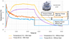 |
Fig. 4 Torque and temperature for the “test cycle” for both configurations (complete bearing/bearing without seal). Temperature is measured at the point on the surface of the OR located axially between two raceways of the bearing. |
2.5 Determination of the convection exchange coefficient
When the bearing is no longer rotating, the frictional heat generation vanishes and the dissipated power becomes zero. In this cooling phase, the bearing is assumed to be thermally isolated from its surroundings in the sense that conductive heat losses through supports are neglected. Under this hypothesis, heat exchange with the external environment is considered to occur only through convection with the ambient air inside the climatic chamber.
The transient heat balance of the bearing can therefore be expressed by the following first-order differential equation:
 (2)
(2)
where S is the exchange surface aera, T and T0 are the bearing temperature and the climate chamber temperature, h is the convective heat transfer coefficient, m is th mass, and Cp is the Specific heat. To determine the convective coefficient h, this differential equation must be solved using the experimental temperature decay curves recorded during the second phase of the test (cooling stage), as illustrated in Figure 4. The identified value of h is subsequently introduced into the finite element model in order to accurately represent the convection boundary condition of the bearing within the thermal chamber. This value is used in the numerical model to characterize the convection of the bearing in the thermal chamber.
Although the lumped temperature assumption used in Equation (2) represents a strong simplification, the good agreement obtained between the experimental and numerical results using the identified convection coefficient suggests that this assumption is acceptable for the present study.
3 Thermomechanical modelling of the bearing
Rolling bearings operating under load and rotational speed are subject to self-heating effects resulting from frictional dissipation. During operation, mechanical energy is progressively converted into thermal energy, mainly at localized interfaces where rolling and sliding interactions occur. In wheel bearing assemblies, the dominant heat sources are associated with the contacts between the rolling elements and the raceways, as well as with the frictional contact between the sealing rings and the hub. In the numerical framework, these mechanisms are introduced as distributed heat sources, whose locations within the bearing system are illustrated in Figure 5.
Once rotation starts, the bearing temperature increases as heat is generated at the contacts and diffuses through the solid components. The thermal response evolves until a stabilized steady-state regime is reached, corresponding to an equilibrium between internal heat generation and thermal losses toward the environment. These losses are governed primarily by conductive transfers within the bearing structure and convective exchanges at its boundaries.
Heat transfer within the assembly may occur through conduction between the different bearing parts, convection with the surrounding air and lubricant, and thermal radiation. Under the present operating conditions, radiative exchanges are considered negligible compared to conductive and convective mechanisms. Therefore, only conduction through the solid components and convection at external and internal surfaces are retained in the model. These thermal boundary conditions, including the main convective surfaces and conductive interfaces, are summarized in Figure 5.
Finite element simulations are performed using Abaqus® (version 2022) [12]. The temperature distribution within the wheel bearing is computed by accounting for the bearing geometry, the thermal properties of the materials, and the main heat transfer mechanisms. In particular, the model requires the specification of:
the thermal parameters of each component (density, conductivity, and specific heat),
the thermal conductance at interfaces in direct contact or separated by thin layers (notably at rolling contacts),
the convection coefficient h identified from experimental cooling curves,
the ambient temperature inside the climatic chamber,
and the time-dependent dissipated power determined from the measured friction torque during the tests.
Initially, the bearing is assumed to be at the chamber ambient temperature T∞. When rotation is imposed, heat generation at the rolling contacts and sealing interfaces leads to temperature rise, followed by diffusion within the rings, hub, and surrounding parts. At the system boundaries, external surfaces exchange heat mainly through convection with the surrounding air, while internal surfaces may also transfer heat to the grease and confined air volumes.
The following sections provide a detailed description of the most critical aspects of this modeling approach, including the definition of heat source terms, the identification of convective boundary conditions, and the treatment of thermal contact conductance between bearing components.
The bearing studied has N = 11 rolling elements per row (Fig. 1). The modeling is performed on an angular segment  to ensure symmetry. The angular sector passes through the center of one ball and the plane between two balls, as shown in Figure 6. Thermal symmetry planes are taken into account by imposing a zero heat flux condition in the direction normal to the symmetry surface, ensuring adiabatic behavior across these planes.
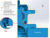 |
Fig. 5 Schematic representation of thermal boundary conditions on the bearing in operation. |
3.1 Materials
In the thermal analysis, the material behavior of each component must be defined through three fundamental properties: the density, the thermal conductivity, and the specific heat capacity. The wheel bearing assembly considered in this study involves five different materials corresponding to the main structural and functional parts: 100Cr6 and C56E2 steels for the rings and metallic elements, PA66 and glass-fiber-reinforced PA66 for polymer components such as the cage, and NBR for the sealing rings.
The thermal properties associated with these materials are taken from the conventional values available in the NTN Europe internal materials database. Figure 6a illustrates the distribution of these materials within the bearing assembly, highlighting their respective locations in the numerical model. In Table 1, the data for the five materials used in the bearing are summarized.
 |
Fig. 6 Numerical model of the bearing: (a) the materials assembly and (b) the mesh. |
Material data.
3.2 Mesh of the system
The mesh elements are selected from the Abaqus® Standard library for thermal transfer models. The elements are in linear order. Unlike mechanical problems, where quadratic elements are recommended, for thermal problems this is not necessarily required. Therefore, DC3D4 elements (4-node linear heat transfer tetrahedrons) are used for the bearing components.
A global element size of 3 mm was chosen for the entire system. The mesh (Fig. 6b) was refined in areas where thermal power is injected (seal, balls, and rings). The element size in the contact zones is 0.1 mm. The model contains a total of 490,902 elements. With these settings, each simulation is completed in approximately 30 min on a standard 8-CPU computer.
3.3 Boundary conditions: convection
The thermal model requires several input parameters, some of which are directly known from experimental measurements, while others must be identified through numerical correlation.
First, the ambient temperature inside the climatic chamber, denoted T∞, is imposed as a constant and constitutes a fully controlled boundary condition. Accordingly, the initial temperature of all bearing and mounting components is also assumed to be equal to T∞ at the beginning of the simulation. In addition, the convective heat transfer coefficient h1 applied to the stationary OR surfaces is considered as a known parameter, since it is experimentally identified from the cooling phase of the test cycle.
In contrast, the convective exchanges occurring within the bearing assembly, particularly in the rotating internal zones, cannot be directly measured. Therefore, two additional convection coefficients, denoted h2 and h3, are introduced and treated as calibration parameters. These coefficients correspond, respectively, to the internal convection between the hub and the outer ring and to the convection at the external surface of the rotating hub.
The convection coefficient h1 is determined from the natural cooling test of the stationary OR in an ambient environment (T = 23°C, constant) after the end of the rotation test, see the decreasing temperature curves between 2600 and 5000 s after stopping the tests in Figure 4. The convection values for the external surface of the rotating hub h1 = 1.64 h1 and for internal zone between the hub (MY) and the outer ring (OR) h3 = 0.65 h1. These two values were determined by correlating the numerical simulation results with the results of the actual tests. Their associated regions in the finite element model are indicated in Figure 7. The values of h2 and h3 are determined by correlating numerical predictions with the experimental thermal measurements obtained on the test bench.
The temperature of the confined air volume inside the bearing is not prescribed but results from the numerical solution. It is computed as a function of time by assuming that it can be approximated by the average temperature of the adjacent hub and OR surfaces in the internal zone.
Finally, experimental observations revealed that a non-negligible amount of heat is conducted through the hub toward the tooling plate. To account for this effect, the temperature measured at the contact interface with the insulating washer is imposed as a boundary condition on the corresponding surface in the numerical model.
 |
Fig. 7 Boundary conditions for convective heat exchange. (a) Outer stationary surfaces with forced convection h1. (b) Outer surfaces in rotation with forced air convection h2. (c) Inner surfaces of bearing h3. |
3.4 Thermal contact conditions
The complete finite element model of the bearing assembly and its tooling plate involves a total of fifteen distinct parts. Consequently, an appropriate definition of thermal contact conditions between neighboring components is required in order to properly describe heat conduction across interfaces.
In thermal modeling, two main approaches are commonly considered to represent interfacial heat transfer between solids: perfect thermal contact and imperfect thermal contact. Perfect contact assumes continuity of both temperature and heat flux across the interface, which is generally justified when the contacting surfaces are conformal, well-machined, and tightly assembled, leading to negligible interfacial thermal resistance.
In the present model, perfect thermal contact is applied to several conformal interfaces, such as the contact between the IR and the hub, as well as between the sealing components and the adjacent metallic parts (outer ring or hub). These interfaces correspond to tight mechanical fits with large contact areas, for which the assumption of negligible thermal resistance is considered acceptable.
Conversely, imperfect thermal contact must be introduced when the contact geometry is non-conformal or when an interstitial medium produces a significant resistance to heat transfer. This situation arises in rolling bearings at the interfaces involving the balls. Ball-to-ring and ball-to-cage contacts are governed by localized Hertzian contacts and are lubricated with grease, which strongly affects the thermal conduction path. Since grease is not explicitly modeled as a physical volume in the finite element mesh, its influence is represented through an equivalent thermal contact conductance introduced at the ball interfaces.
Accordingly, the thermal conductance curve shown in Figure 8 is defined based on the equivalent conductance of an interstitial medium separating the contacting surfaces. In the present case, the non-perfect thermal contact between the rolling elements and the surrounding components (IR, OR, and cage) is modeled using the thermal contact interaction available in Abaqus. The thermal conductance hc is evaluated assuming a thin layer of lubricant (grease) between the contacting surfaces. It is calculated from the classical relation hc=λ/e, where e represents the effective thickness of the interstitial medium and λ its thermal conductivity. In this study, a constant thermal conductivity of the grease equal to λ = 0.8 W/(m K) is considered. The conductance curve is then constructed by varying the effective thickness e, leading to the relationship presented in Figure 8.
Finally, in order to avoid numerical inconsistencies between multiple neighboring interactions, the surface of each ball is partitioned into distinct regions corresponding to its contacts with IR, OR, and the cage, as shown in Figure 9.
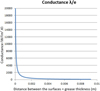 |
Fig. 8 Conductance curve introduced in Abaqus®. |
 |
Fig. 9 Partitioning of the ball surface for contact management. Blue: contact with IR; green: contact with cage; and orange: contact with OR. |
3.5 Boundary conditions with dissipated power
In the numerical model, the thermal load is introduced through dissipated mechanical power estimated directly from the preliminary experimental measurements presented in the previous sections. The friction torque recorded during the tests is converted into an equivalent heat power, which is assumed to be fully transformed into thermal energy at the main frictional interfaces of the bearing assembly.
Two distinct contributions are considered: heat generation at the rolling contacts between the balls and the raceways, and heat generation at the seal lip–hub contact. For the complete bearing configuration, the total injected power PTotal is determined from the measured torque evolution during the test. In contrast, for the configuration with cut seal lips, frictional losses are assumed to originate only from the rolling contacts, leading to a power contribution denoted by Pballs-raceways, which is distributed exclusively at the ball-to-ring interfaces.
Assuming that the rolling-contact dissipation remains identical in both configurations, the additional power associated with the sealing system can be isolated and introduced into the model as:
 (3)
(3)
Taking advantage of cyclic symmetry, the full bearing is reduced to an angular sector in the finite element model. Since the bearing contains N = 11 balls per row and the sector represents half of the full row, the total power must be scaled accordingly. The power applied to the simulated segment is therefore:

In Abaqus®, heat generation is imposed using the Total Flux option, where the total power dissipated over a given surface is prescribed in watts.
At the rolling element interfaces, heat generation does not occur at a fixed location, as the contact zone continuously moves with the rotation of the bearing. Under the assumption of sufficiently high rotational speed, this moving heat source can be represented by an equivalent time-averaged heat flux. The dissipated power is therefore applied as a uniformly distributed heat flux over the active raceway surfaces and across the entire ball surface. The width of the active raceway band is determined using the SharcNT technical calculation software, which provides rolling element loads and contact dimensions based on the bearing geometry, loading conditions, and lubrication parameters [13].
In contrast, the seal lip–hub contact zones are clearly identifiable and remain spatially fixed. The hub surface is partitioned at the lip locations, allowing the seal-related power Pseal contact to be directly injected into these regions, as shown in Figure 10. The distribution of dissipated power among the three sealing lips is non-uniform, depending on the respective contact forces and radial positions. Numerical calculations of the seal assembly indicate that lip 1 contributes approximately 30% of the sealing friction power, lip 2 about 50%, and lip 3 about 20%, as illustrated in Figure 10.
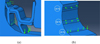 |
Fig. 10 Dissipated friction power at seal contact: (a) local view of the seal and (b) power distribution over the 3 contact areas. |
4 Results and discussion
The temperature maps from IR measurements and from simulation at stabilized state are shown in Figure 11; good agreement can be observed. The temperature evolutions at one point on the outer surface of the OR identified in Figure 4, obtained from the experimental test and from numerical simulation, are close, with a maximum difference of 5% (Fig. 12).
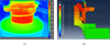 |
Fig. 11 Temperature fields (°C) at the stabilized state: (a) infrared measurements and (b) simulation results. |
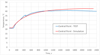 |
Fig. 12 Comparison of the temperature variations at the same point on the surface of the OR obtained from the simulation and from the experimental test. |
5 Validation on a second bearing technology
The objective of this section is to further validate the thermo-mechanical finite element framework developed and identified in the previous sections by applying it to a second wheel bearing technology with a significantly different geometry (Fig. 13). This additional case study is intended to assess the robustness and transferability of the modeling approach beyond the initial bearing configuration. The two bearings investigated in this study present significant structural differences. Bearing 1 corresponds to a non-driven configuration without axial load, whereas Bearing 2 is a driven configuration subjected to axial loading. In addition, Bearing 2 incorporates two sealing systems, compared to a single seal for Bearing 1. The geometrical dimensions also differ, with Bearing 2 having a larger diameter, approximately 1.4 times that of Bearing 1. Finally, while both bearings feature two rows of rolling elements, Bearing 1 has identical pitch diameters for both rows, whereas Bearing 2 is characterized by two rows with different pitch diameters.
Due to the geometric symmetry of the bearing components, the smallest representative computational domain corresponds to one quarter of the complete assembly. Therefore, the numerical simulation of bearing n°2 was carried out on a 1/4 sector model, as illustrated in Figure 13.
A series of experimental tests was performed on bearing n°2 at the same rotational speed of 739 rpm, and the corresponding simulations were conducted under identical modeling assumptions.
Importantly, no additional parameter identification or readjustment was introduced for the second bearing configuration. All thermal parameters used in the model are either directly measured or based on known physical properties (material properties and grease conductivity) or identified independently from dedicated experiments (external convection coefficient h1). Only two convection coefficients, associated with the rotating hub and the internal cavity (h2 and h3), were initially calibrated using the first bearing by correlating numerical results with experimental thermal fields on the hub and OR surfaces.
These same values, without any modification, were then directly applied to the second bearing configuration, despite its significantly different geometry and operating conditions.
The infrared thermal fields recorded during the test and those predicted by the finite element model show again a very close agreement, as illustrated in Figure 14. Figure 15 compares the temperature evolution at a selected point on the OR surface. The simulation slightly overestimates the measured temperature by only 2.8%, which remains within an excellent prediction range for such a complex thermo-mechanical system.
These results demonstrate that the proposed FEM framework is able to reliably reproduce the thermal behavior of different bearing technologies based solely on experimentally measured dissipated power at the ball–raceway and seal–hub interfaces. The successful validation on a second bearing geometry confirms not only the relevance of the parameters identified in the initial phase but also the robustness of the overall modeling and calibration methodology.
Furthermore, the numerical simulation provides access to the full three-dimensional temperature distribution within the bearing assembly, including regions that are not experimentally accessible, as illustrated in Figure 16. This constitutes a major advantage of the proposed numerical approach for predictive thermal assessment and design purposes.
 |
Fig. 13 Bearing n°2: (a) view of the bearing and (b) simulation model. |
 |
Fig. 14 Bearing n°2, temperature fields (°C) at the end of the test (t = 4500 s): (a) infrared measurements and (b) simulation results. |
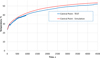 |
Fig. 15 Temperature evolution at point P during numerical and real tests in external surface of other bearing. |
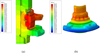 |
Fig. 16 Thermal field of the bearing n°2 at the end of the simulation (corresponding to the end of the test, time = 4500 s). |
6 Conclusion
In this work, a dynamic thermo-mechanical finite element modeling framework has been developed to predict the thermal behavior of complete wheel bearing assemblies. The model explicitly accounts for the main heat generation mechanisms associated with rolling contacts and sealing interfaces, as well as for conductive and convective heat transfer within the bearing system and its test bench environment. The required thermal parameters, including conduction, convection, and interfacial heat exchange coefficients, were either directly measured or identified through a systematic experimental–numerical correlation procedure.
The numerical approach was validated using a dedicated experimental test bench instrumented for dynamic measurements of rotational speed, friction torque, and ambient conditions. High-resolution infrared thermography was employed to capture transient and steady-state temperature fields on the bearing surface, providing a robust basis for comparison with numerical predictions. The proposed model was successfully validated on two wheel bearings with significantly different geometries, without any additional parameter recalibration. For both configurations, the agreement between measured and simulated temperatures remained within a deviation range of approximately 3%–5%, demonstrating the reliability and transferability of the modeling strategy.
Beyond quantitative validation, the developed three-dimensional thermo-mechanical model provides detailed insight into the temperature distribution within all bearing components, including regions that are not experimentally accessible. This capability represents a significant advantage for analyzing the influence of geometry, sealing design, and power dissipation on bearing thermal behavior under realistic operating conditions.
The present work establishes a robust methodological framework for thermally driven assessment of wheel bearings based on experimentally derived dissipated power. Future developments will focus on extending this approach toward fully predictive design tools by coupling the finite element model with analytically or numerically estimated frictional power inputs. In particular, integrating bearing torque predictions from dedicated calculation tools and improving the modeling of seal friction, including temperature-dependent material behavior and lubrication effects, constitute promising directions for further investigation. Such developments would enhance the applicability of the proposed framework during early design stages, where experimental data are not yet available.
Funding
The authors declare that no specific funding was received for this work.
Conflicts of interest
The authors declare that they have no conflict of interest.
Data availability statement
The data supporting the findings of this study are not publicly available due to industrial confidentiality constraints.
Author contribution statement
Conceptualization: Olga Incandela, Sébastien Guillaume, Emile Roux, and Pascale Balland;
Methodology: Olga Incandela, Sébastien Guillaume, Emile Roux, and Pascale Balland;
Software: Olga Incandela, Sébastien Guillaume, Emile Roux, and Pascale Balland;
Validation: Olga Incandela, Sébastien Guillaume, Emile Roux, and Pascale Balland;
Formal Analysis: Olga Incandela, Sébastien Guillaume, Emile Roux, and Pascale Balland;
Investigation: Olga Incandela, Sébastien Guillaume, Emile Roux, and Pascale Balland;
Resources: Olga Incandela, Sébastien Guillaume, Emile Roux, and Pascale Balland;
Data Curation: Olga Incandela, Sébastien Guillaume, Emile Roux, and Pascale Balland;
Writing–Original Draft Preparation: Olga Incandela;
Writing–Review & Editing: Sébastien Guillaume, Emile Roux, and Pascale Balland;
Visualization: Olga Incandela, Emile Roux;
Supervision: Sébastien Guillaume, Pascale Balland.
References
- A. Neurouth, Etude de la performance énergétique d’une transmission, PhD thesis, Institut National des Sciences Appliquées de Lyon, 2016. https://lamcos.insa-lyon.fr/files/theses/1240-thesepdf.pdf [Google Scholar]
- A. Palmgren, Ball and roller bearing engineering, SKF Industrial Publications, 1959 [Google Scholar]
- T.A. Harris, M.N. Kotzalas, Rolling bearing analysis, 5th ed., CRC Press, 2006 [Google Scholar]
- J.-L. Ligier, B. Noel, F. Ville, Friction reduction and reliability for engine bearings, Lubr. Basel Switz. 3, 569–587 (2015) [Google Scholar]
- V. Bakolas, C. Evangelos, P. Nikolakopoulos, Global energy consumption of ball bearings, Tribol. Trans. (2021). https://doi.org/10.1080/10402004.2021.1946227 [Google Scholar]
- B. Bossmanns, J.F. Tu, A thermal model for high speed motorized spindles, Int. J. Mach. Tools Manuf. 39, 1345–1366 (1999) [Google Scholar]
- J. Takabi, M.M. Khonsari, Experimental testing and thermal analysis of ball bearings, Tribol. Int. 60, 93–103 (2013) [Google Scholar]
- W. Wu, J. Hu, S. Yuan, Flow and heat transfer in jet cooling rolling bearing, in: Heat Mass Transfer – Advanced Science Technology Application, IntechOpen, 2019. https://doi.org/10.5772/intechopen.84702 [Google Scholar]
- M.M. Tasić, R.M. Mitrović, Ž.Z. Mišković, Experimental and numerical transient thermal analysis of the idler bearing housing made of steel or polymer material, Therm. Sci. (2022). https://doi.org/10.2298/TSCI220429129T [Google Scholar]
- J. Xu, J. Zhang, Z. Huang, L. Wang, Calculation and finite element analysis of the temperature field for high-speed rail bearing based on vibrational characteristics, J. Vibroengineering 17 (2015) [Google Scholar]
- X.P. Maldague, Theory and practice of infrared technology for nondestructive testing, John Wiley & Sons, 2001 [Google Scholar]
- Dassault Systèmes, ABAQUS 2022 documentation, Dassault Systèmes Simulia Corp., Providence, RI, USA, 2022. https://www.3ds.com/support/documentation/ [Google Scholar]
- T. Ishikawa, H. Hirukawa, M. Izumi, C. Burnet, Development of technical calculation systems for rolling bearings, NTN Tech. Rev. 91–95 (2021) [Google Scholar]
Cite this article as: O. Incandela, S. Guillaume, E. Roux, P. Balland, Development and validation of a thermal finite element simulation of a wheel bearing, Mechanics & Industry 27, 24 (2026), https://doi.org/10.1051/meca/2026021
All Tables
All Figures
|
Fig. 1 Wheel bearing NTN third generation. |
| In the text | |
|
Fig. 2 Bearing test setup. (a) Cross-sectional view. (b) Setup inside the temperature-controlled thermal chamber. |
| In the text | |
|
Fig. 3 Bearing test setup for torque measurement: (a) schematic diagram illustrating the measurement principle and (b) top view of the experimental system. |
| In the text | |
|
Fig. 4 Torque and temperature for the “test cycle” for both configurations (complete bearing/bearing without seal). Temperature is measured at the point on the surface of the OR located axially between two raceways of the bearing. |
| In the text | |
|
Fig. 5 Schematic representation of thermal boundary conditions on the bearing in operation. |
| In the text | |
|
Fig. 6 Numerical model of the bearing: (a) the materials assembly and (b) the mesh. |
| In the text | |
|
Fig. 7 Boundary conditions for convective heat exchange. (a) Outer stationary surfaces with forced convection h1. (b) Outer surfaces in rotation with forced air convection h2. (c) Inner surfaces of bearing h3. |
| In the text | |
|
Fig. 8 Conductance curve introduced in Abaqus®. |
| In the text | |
|
Fig. 9 Partitioning of the ball surface for contact management. Blue: contact with IR; green: contact with cage; and orange: contact with OR. |
| In the text | |
|
Fig. 10 Dissipated friction power at seal contact: (a) local view of the seal and (b) power distribution over the 3 contact areas. |
| In the text | |
|
Fig. 11 Temperature fields (°C) at the stabilized state: (a) infrared measurements and (b) simulation results. |
| In the text | |
|
Fig. 12 Comparison of the temperature variations at the same point on the surface of the OR obtained from the simulation and from the experimental test. |
| In the text | |
|
Fig. 13 Bearing n°2: (a) view of the bearing and (b) simulation model. |
| In the text | |
|
Fig. 14 Bearing n°2, temperature fields (°C) at the end of the test (t = 4500 s): (a) infrared measurements and (b) simulation results. |
| In the text | |
|
Fig. 15 Temperature evolution at point P during numerical and real tests in external surface of other bearing. |
| In the text | |
|
Fig. 16 Thermal field of the bearing n°2 at the end of the simulation (corresponding to the end of the test, time = 4500 s). |
| In the text | |
Current usage metrics show cumulative count of Article Views (full-text article views including HTML views, PDF and ePub downloads, according to the available data) and Abstracts Views on Vision4Press platform.
Data correspond to usage on the plateform after 2015. The current usage metrics is available 48-96 hours after online publication and is updated daily on week days.
Initial download of the metrics may take a while.