| Issue |
Mechanics & Industry
Volume 19, Number 1, 2018
|
|
|---|---|---|
| Article Number | 102 | |
| Number of page(s) | 9 | |
| DOI | https://doi.org/10.1051/meca/2017035 | |
| Published online | 24 August 2018 | |
Regular Article
Estimation of the resonance amplitude in machines with inertia vibrator in the coast-down phase
AGH University of Science and Technology, al. Mickiewicza 30,
30-059 Krakow,
Poland
* e-mail: cieplok@agh.edu.pl
Received:
14
September
2016
Accepted:
14
October
2017
The work concerns mechanical systems with transient resonance formed as a result of an unbalanced rotating mass passing through an area of the system's natural frequency. In particular, this concerns over-resonant vibrating machines driven by inertia vibrators, which during start-up and coast-down pass through the natural frequency area related to the vibrating mass – flexible suspension system. The work analyses a system consisting of a soft-mounted machine body excited into vibrations by means of the inertia vibrator in order to designate the amplitude of resonant vibration, taking into consideration strong coupling between movements of the body and vibrator. The research results are presented in the form of nomograms and approximation formulas expressed in terms of relative parameters. The results of the theoretical research were verified on the laboratory model and industrial machines.
Key words: Vibratory machines / transient resonance / estimation of maximal amplitude / nomogram method
© AFM, EDP Sciences 2018
1 Introduction
Rotating machines with unbalanced rotors mounted on flexible suspensions may, during their start-up and coast-down, be subjected to strong vibrations. The appearance of resonance is connected with the interaction of inertia forces of unbalanced rotors with the machine body in the field of the system's vibration frequency: vibrating mass – flexible suspension. Defining the amplitude of these vibrations in the case of stationary resonance does not represent a problem. Their values are decided by the particular integrals of dynamic equations of motion which, as a result of assuming a constant angular velocity of the rotor, lead generally to a linear algebraic equation.
The case is more complicated when we have to deal with transient states. Then, due to the variable in time rotational velocity of the rotor, the dynamic equations of motion are considered as non-linear. The simplest system that we may deal with, consisting of a vibrating mass excited with the help of an unbalanced rotor, is described with the fourth order differential equation. We do not know the analytical form of this equation's solution. Therefore, the published theoretical works concerning this matter are based either on simplifications or on numerical models.
Simplification can generally lead to two cases. In the first one, the simplification of the physical structure of the system is performed to such degree that calculations to obtain analytical formulas can be conducted. In this way, formulas for resonant vibration amplitude were obtained by Michalczyk [1,2] as well as by Agranowska and Blechman [3]. In both papers, the researchers used energy – kinetic energy balance of the rotational motion and vibrating mass or the kinetic energy of the vibrating mass and the potential energy of the suspension.
In the second case, the simplification concerns the dynamic analysis of the equation of motion assuming, for example, the previously mentioned course of the rotor angular velocity to be known. This case is more widely explored in the literature. These include the pioneering works of Lewis [4] and Kac, and then the works of Fearn and Millsaps [5], Leul, Dorning, Fernlund [6], Hirano [7], Banaszewski and Turkiewicz [8] or Markert and Seidler [9]. The last of these works contains the overview of the problem.
The assumption of a known course of rotating velocity may lead to serious errors in the resonant amplitude definition [10,11]. If, during the start-up phase, the dominating role is played by the drive moment of the engine, and the acceleration and angular velocity of the rotor can be defined on its basis, then during free coast-down the matter looks less optimistic. The motion of the rotor is decelerated by the motion resistance and interaction of the machine parts. This last factor, which in the literature is defined as the vibration moment [1], plays a key role and is a basic cause of rotor velocity breakage in the resonance zone. The usage of analytical formulas introduced in the mentioned works, and based on rotor deceleration, leads to serious errors, and in the case of machines with a large unbalance, such as vibrating machines, it loses its sense.
In works [12–15] the analysis was carried out on a system consisting of a mass mounted on a symmetrical flexible suspension excited into vibrations with the help of an inertia vibrator. Thanks to the transformation of the dynamic equation of motion to a set of coordinates for the rotor velocity, and referring the coordinates of motion to the reference value, equations were obtained which for coast-down phases were expressed by only two relative parameters, i.e. the forced-inertia parameter connecting the unbalanced rotor with the vibrating mass and with the moment of rotor inertia as well as through relative damping of the suspension system. This allowed to determine nomograms which could define the amplitude of resonant vibrations in the case of free coast-down.
This paper widens the knowledge concerning transient resonance by performing analysis of a system of non-symmetrical suspension, which is more often met in practice.
2 Mathematical model
Figure 1 presents the model of the rotating machine with three degrees of freedom mounted on a non-symmetrical flexible suspension, which is excited into vibrations using an unbalanced rotor.
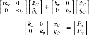
In the Cartesian coordinate system, dynamic equations of motion may be written in the form of the set of dependencies (1).
 (1a)
(1a)
 (1b)
(1b)
 (1c)
where e designates the radius of the unbalanced mass m, J – mass moment of inertia of the drive shaft, M − drive moment, kx, ky, bx, by – coefficients of elasticity and damping on the x and y axes.
Assuming equality between the relative damping γ of the motion of the vibrating mass in x and y directions (Eq. (2)):
 (2)
the degree of non-symmetry of the suspension can be expressed using the relative parameter β, according to the dependencies (3).
 (3a)
(3a)
 (3b)
(3b)
Analogically, as in the work [14], the dynamic equations of motion were transformed and expressed in a set of coordinates for the rotor velocity. The mutual placement of the systems: rotating and fixed, is presented in Figure 2. The matrix of transformation [T] equation (4) enabled the dependency between the coordinates of the mass centre in both systems to be designated.
 (4)
(4)
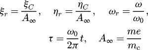
In order to increase the ability to compare solutions, values such as time, coordinates of motion, angular velocity of the rotor, were referred to the reference values. According to equation (5), time was referred to the natural vibration period in the main motion direction, the angular velocity to the natural vibration frequency in the main motion direction, while the coordinate of the body's mass centre to the asymptotic amplitude of body vibrations.
 (5)
(5)
The dynamic equations of motion after transformations, took the set of equation (6) form.
 (6a)
(6a)
 (6b)
(6b)
 (6c)
where
 (7a)
(7a)
 (7b)
(7b)
 (7c)
(7c)
 (8a)
(8a)
 (8b)
(8b)
 (8c)
(8c)
Thanks to the transformation and introduction of relative coordinates, it was possible to define relative parameters expressing the machine's dimensions, i.e. the parameter of inertia-imbalance:
 (9)
as well as the parameter of excitation:
 (10)
(10)
 |
Fig. 1 Model of the vibrating machine. |
 |
Fig. 2 Placement of the body's center of mass mk in the systems 0xy and 0ξη. |
3 Nomograms
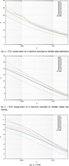
As the result of creating relative parameters, the set of 9 physical parameters describing machines, including: body mass mk, vibrator mass m, radius of the unbalanced vibrator e, coefficients of suspension flexibility kx, ky, bx, by, moment of inertia of the drive shaft J (together with the vibrator) and drive moment M, was decreased to 4 relative parameters: σ, γ, β, q. This provided the capability of designating nomograms connected with the amplitude of resonant vibrations depending on the system parameters, without the need for simplifications. In the case of resonance appearing in the free coast-down of a rotor, it is even more beneficial, because the excitation parameter q takes the zero value, and braking of the rotor and slowing down of the machine motion occurs only thanks to the diffusion of energy in the damping elements bx and by. Figure 3 presents three such nomograms. They present the coefficient of vibration amplitude multiplication
 (11)
for a steel suspension (Fig. 3a), a rubber suspension (Fig. 3b) and for a strongly dumped case of elastic suspension (Fig. 3c).
Nomograms were obtained by the numerical integration of the set of equations (6). The start-up, steady state and the machine coast-down were simulated for the typical variability range of σ and β parameters. On the basis of the vibration waveforms of the machine body in the coast-down phase the resonance vibrations amplitudes Ares were determined. They allowed to determine coefficients of the vibration amplitude α multiplication, in relation to A∞ value.
For systems in which the machine body performs rectlinear movement, the characteristics for β = 1000 may be used to define the coefficient of vibration amplitude multiplication. It can also be seen that for this type of movement, the average vibration moment for the vibration period is two times lower than for the motion of the body on a symmetrical suspension. This enables the use of a nomogram for symmetrical suspensions (described in detail in the work [15]) using two-times grater value of the parameter σ. This correctness may be confirmed by comparing the characteristics presented in Figure 3, for β = 1 and β = 1000.
Analysing the nomograms, it can generally be stated that an increase of the parameter σ causes a decrease of the coefficient of vibration amplitude multiplication α, and non-symmetry of the suspension increases its value. In the case of non-symmetry, we observe visible irregularities characteristic of unexpected raises and intertwining.
These irregularities which are visible, especially at lower values of damping, can be explained by means of computer simulations. In Figure 4a and d, the amplitudes of the machine body vibrations for a symmetrical suspension and conducted rectlinearlly are presented, respectively. In these cases, only one resonance occurs and the characteristics of the coefficient α monotonically and smoothly reduce their values. In the case of non-symmetrical suspensions Figure 4b and c, two resonances appear, which to a larger or smaller degree interact with each other. This interaction means that the second resonance to take place may take a value larger in relation to the first one, which generally appears as a disorder of the regular course of characteristics.
In the case of suspensions made of steel elements, an approximating formula for nomograms was accepted in the form of a hyperbola (Eq. (12)). The characteristic features of strongly damped suspensions, e.g. of rubber, show greater regularity, and on graphs with a logarithmic scale they are approximated to straight line (Eq. (13)). Tables 1 and 2 present values of coefficient a, b, c for both cases presented above.
 (12)
(12)
 (13)
(13)
 |
Fig. 3 Coefficient of vibration amplitude multiplication. |
 |
Fig. 4 Time graphs. |
Coefficients of approximating hyperbola.
Coefficients of linear approximation.
4 Experimental research
The experimental sample verification of theoretical considerations was obtained by tests conducted for a vibrating screening machine, presented in Figure 5. The machine consisted of a frame, to which, with the help of steel springs, a sieve with an inertia vibrator was attached. The vibrator was placed in the centre of the vibrating sieve and driven with an electric motor. The way of suspending and placing the vibrator ensured a translation movement of the sieve, and therefore a motion was in accordance with the accepted theoretical model. Suspensions of this type are characterised by strong non-symmetry. Springs work only vertically, however, horizontal return motion of the sieve (axial movement) is mainly ensured by gravity.
Due to a relatively low frequency of natural vibrations (approx. 3 Hz) and a relatively high vibration amplitude (over a dozen millimetres), registration of displacement was conducted by means of a visual method based on a fast camera. A detailed description of the used method can be found in the work [16].
Figures 6 and 7 present the waveforms of the vertical and horizontal coordinates of the mass centre of the sieve of the screening machine. As can be seen, the greatest vibration amplitude took place in the coast-down in a vertical direction and equalled 15.04 mm.
Based on the value of relative parameter σ (Eq. (15)), as well as nomograms from Figure 3a, it is possible to read the coefficient of vibration amplitude multiplication α ≈ 8.04 (compare Eq. (17)). Multiplying its value with the base amplitude (Eq. (16)) the maximum vibration amplitude (Eq. (18)) in the coast-down of the machine was designated. Comparing the result to the measured value, a relative error equalling approx. 70% was obtained.
 (14)
(14)
 (15)
(15)
 (16)
(16)
 (17)
(17)
 (18)
(18)
 (19)
(19)
This relatively high error was mainly caused by assuming the nomogram intended for steel, while in this particular case, the elastic suspension system reveals significantly higher damping. On the basis of natural vibrations of the sieve unit (Fig. 8) it is possible to determine, on the grounds of the logarithmic decrement of vibrations decay, more accurate value of the damping coefficient. According to calculations in equation (20), γ = 0.039.
 (20a)
(20a)
 (20b)
(20b)
Now, on the bases of Figure 3b and c, it is possible to determine the average value of the multiplication ratio of vibrations α. It is equal  , which provides the resonance vibrations amplitude app. 18.8 mm and relative error 26%.
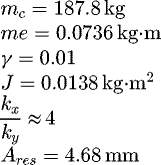
It is worth referring to publication [17], which shows the results of machine vibration measurements conducted on a laboratory model – Figure 9. Mounted on four springs, the machine was characterised by a typical non-symmetry of the suspension vertically and horizontally. Based on Figure 10 (Fig. 6b on p. 48 of the publication), it is possible to read the amplitude of resonant vibrations during coast-down of the machine. In turn, details of the laboratory stand construction and the basic values of the machine's physical parameters can be found in the work [14] on pp. 70–72. Synthetically combining the data from both publications, it is possible to give the following values:
 (21)
(21)
On their basis, it is possible to designate the relative parameter σ = 2.1 ⋅ 10−3 and further on the basis of the nomogram for β = 0.25, the value of the coefficient of amplitude multiplication α ≈ 13.95 – calculation equations (22) and (23). Referring its value to the base amplitude, it is possible to designate the theoretical value of the resonant amplitude. In this case, the relative error of the theoretical and measured values equalled 17.5%.
 (22)
(22)
 (23)
(23)
 |
Fig. 5 Photograph of the screen unit. |
 |
Fig. 6 Coast-down phase. Vertical vibrations of the centre of the screen unit. |
 |
Fig. 7 Coast-down. Horizontal vibrations of the centre of the screen unit. |
 |
Fig. 8 Free vertical vibrations of the center of the screen unit. |
5 Conclusions
The work presents a method for designating the amplitude of resonant vibrations of machines and devices mounted on flexible suspensions and excited using an unbalanced rotor. The research is limited to the case of the free coast-down phase of a rotor due to the fact that during this phase vibrations of the greatest amplitude are observed. The nomograms presented in the work allow the maximum vibration amplitude to be designated based only on the system's physical parameters, without the necessity to designate the angular deceleration of the rotor. This is the main difference as compared with existing publications and is of primary significance. It relieves users of the difficulty of estimating decelerations, which during the rotor movement through areas of resonance violently change their values – from lower before entering into resonance, to significantly higher while the rotor passes through resonance. In the author's opinion, due to the evidently variable angular velocity of the rotor in its resonance area, researches based on the rotor deceleration are of no application.
Exceptions can constitute machines with small unbalances of a rotor in reference to its inertia or with forced braking, ensuring the angular deceleration maintenance at the given level.
Of course, there are energy approaches as mentioned in the introduction of the works of Michalczyk, however, these assume the complete flow of kinetic energy between the rotating movement of the rotor and the translation movement of the vibrating mass. This assumption may be accepted only in the case of highly-unbalanced rotors, e.g. a vibrating machine driven with an inertia vibrator. As can be noticed, the formula for vibration amplitude  depends in this case only on the vibrating mass and mass moment of inertia of the drive shaft, and does not take into consideration the influence of suspension damping or vibrator unbalance; while these parameters, as can be seen from the presented nomograms, are of significance. Using the above-mentioned formula for the amplitude of resonant vibrations, we would receive 28 mm for the screening machine and 8.6 mm for the laboratory model.
The work also allows the visual comparative analysis of the influence of a machine's physical parameters on the analysed values, which in the case of non-linear equations is significant. In particular, the influence of the degree of a suspension's non-symmetry on the vibration amplitude increase is very clearly presented. The results obtained during laboratory tests confirmed the usefulness of nomograms. The errors obtained while comparing the experimental results with the estimations from nomograms did not exceed thirty percent, which in comparison with a few hundred percent shown in the work [10] is a significantly better result and qualifies for technical applications.
Nomenclature
α: coefficient of vibration amplitude multiplication
β: coefficient of suspension non-symmetry
γ: relative coefficient of damping
σ: parameter of inertia-imbalance
ξC, ηC: coordinates of the body centre of mass
ξr, ηr: relative coordinates of the body centre of mass
ω: angular velocity of unbalance mass
ω0: angular velocity of natural vibration of machine mass
ωr: relative angular velocity of unbalance mass
a, b, c: coefficient of approximation
Ares: resonance amplitude of vibration
A∞: asymptotic amplitude of vibration
bx, by: coefficients of damping
e: radius of the unbalanced mass
J: mass moment of inertia of the drive shaft
kx, ky: coefficients of elasticity
mc: total mass of machine, mc = mk + m
RMSD: root-mean-square deviation
Acknowledgments
The project described in this paper has been executed within the Project No. 11.11.130.955.
References
- J. Michalczyk, P. Czubak, Methods of determination of maximum amplitudes in the transient resonance of vibratory machines, Arch. Metall. Mater. 55 (2010) 695–705 [Google Scholar]
- J. Michalczyk, Transient resonance of machines and devices in general motion, J. Theor. Appl. Mech. 50 (2012) 577–587 [Google Scholar]
- E.A. Agranowskaya, I.I. Blekhman, Ob ocenke rezonansnykh amplitud kolebanii prii wybiege systemy so mnogimi stepenyami swobody, Dinamika Maszyn, Nauka, Moskva, 1969 [Google Scholar]
- F.M. Lewis, Vibration during acceleration through a critical speed, ASME Transactions, J. Appl. Mech. 54 (1932) 253–261 [Google Scholar]
- R.L. Fearn, K. Millsaps, Constant acceleration of an undamped simple vibrator through resonance, J. R. Aeronaut. Soc. 71 (1967) 680 [CrossRef] [Google Scholar]
- I. Fernlund, Running through the critical speed of a rotor. No. 277, Transactions of Chalmers University of Technology, Gothenburg, Sweden, 1963 [Google Scholar]
- I. Hirano, Y. Matsukura, M. Kiso, Behaviour of vibrating system passing through the resonances, Mitsubishi Denki Ghio, 42 (1968) 11 [Google Scholar]
- T. Banaszewski, W. Turkiewicz, Analiza wzrostu amplitudy drgań" przesiewaczy wibracyjnych podczas rozruchu, Mechanizacja i automatyzacja górnictwa, 144 (1980) 11 [Google Scholar]
- R. Markert, M. Seidler, Analytically based estimation of the maximum amplitude during the passage through resonance, Int. J. Solids Struct. 38 (2001) 1975–1992 [CrossRef] [Google Scholar]
- J. Michalczyk, G. Cieplok, Rezonans przejściowy maszyn wirnikowych − przyczyny błędów oszacowań. Zeszyty Naukowe AGH, Mechanika 13 (1994) 47–67 [Google Scholar]
- J. Michalczyk, G. Cieplok, Transient resonance in limited power systems, Chall. J. Struct. Mech. 2 (2016) 163–168 [Google Scholar]
- G. Cieplok, Ampliduda drgań symetrycznie posadowionej maszyny wibracyjnej podczas rezonansu przejściowego, Czasopismo Techniczne, 1-M2008, 2008, pp. 37–45, Wydawnictwo Politechniki Krakowskiej, http://yadda.icm.edu.pl/yadda/element/bwmeta1.element.baztech-article-BGPK-2494-9295 [Google Scholar]
- G. Cieplok, Quality analysis of symmetrically supported vibratory machine taking into account a rotor stall in resonance, Mach. Dyn. Probl. 31 (2007) 14–22 [Google Scholar]
- G. Cieplok, Stany nieustalone nadrezonansowych maszyn wibracyjnych, nr 185 (Transient states in over-resonant vibrating machines), AGH University of Science and Technology Press, AGH-UST, Krakow, Poland, 2009 [Google Scholar]
- G. Cieplok, Verification of the nomogram for amplitude determination of resonance vibrations in the run-down phase of a vibratory machine. J. Theor. Appl. Mech. 47 (2009) 295–306 [Google Scholar]
- M. Giergiel, P. Kohut, Optical 3D measurement of amplitude of vibrations, Pol. J. Environ. Stud. 20 (2011) 61–65 [Google Scholar]
- M. Giergiel, P. Kohut, Analysis of dynamics of vibratory machines applying vision based measurement, Mech. Mech. Eng. 15 (2011) 43–51 [Google Scholar]
Cite this article as: G. Cieplok, Estimation of the resonance amplitude in machines with inertia vibrator in the coast-down phase, Mechanics & Industry 19, 102 (2018)
All Tables
All Figures
 |
Fig. 1 Model of the vibrating machine. |
| In the text | |
 |
Fig. 2 Placement of the body's center of mass mk in the systems 0xy and 0ξη. |
| In the text | |
 |
Fig. 3 Coefficient of vibration amplitude multiplication. |
| In the text | |
 |
Fig. 4 Time graphs. |
| In the text | |
 |
Fig. 5 Photograph of the screen unit. |
| In the text | |
 |
Fig. 6 Coast-down phase. Vertical vibrations of the centre of the screen unit. |
| In the text | |
 |
Fig. 7 Coast-down. Horizontal vibrations of the centre of the screen unit. |
| In the text | |
 |
Fig. 8 Free vertical vibrations of the center of the screen unit. |
| In the text | |
 |
Fig. 9 Photograph of the research stand: 1–machine body, 2–vibrator, 3–spring, 4–motor, 5–seat [14]. |
| In the text | |
 |
Fig. 10 The courses of center of mass machine body in x, y, z directions. Description in [17]. |
| In the text | |
Current usage metrics show cumulative count of Article Views (full-text article views including HTML views, PDF and ePub downloads, according to the available data) and Abstracts Views on Vision4Press platform.
Data correspond to usage on the plateform after 2015. The current usage metrics is available 48-96 hours after online publication and is updated daily on week days.
Initial download of the metrics may take a while.


