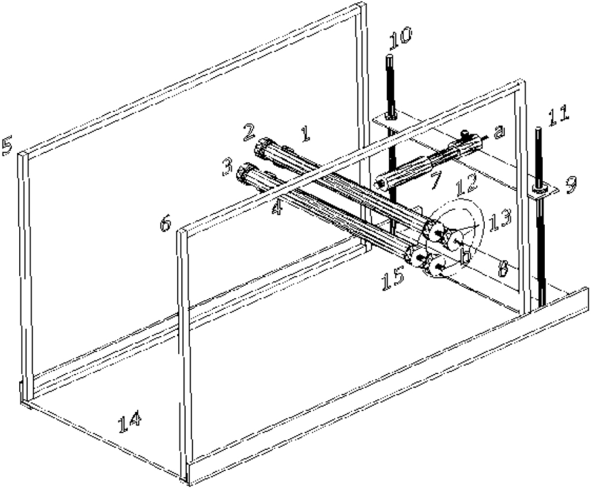
Fig. 5

Download original image
Schematic of the test system. 1, 2, 3, 4 – Circular cylinders that are capable of circulation around their axis of symmetry; 5, 6 – Walls with materials of Perspex glass, which are surrounded by wooden frames and have the duty to hold the cylinders; 7 – Nozzle; 8 – Fixed part of nozzle holder frame 9- Moving part of nozzle holder frame; 10, 11 – Regulating screws of nozzle height; 12 – Conveyer for adjusting the amount of circulation in circular cylinder; 13 – Index for determination of the amount of cylinder circulation; 14 – The main frame that all the above components are located on it; 15 – Screws for binding the cylinders to the walls of Perspex glass material with wooden frames. At the end of nozzle and cylinders, there are some parts that are shown in the Figures 6a and 6b and are defined as: (a) Location of connecting the pipe that is fed from air compressor and contains compressed; air. (b) Pressure outlet on the cylinder that is connected to a side of a U-shaped manometer to measure the pressure on the surface of cylinder.
Current usage metrics show cumulative count of Article Views (full-text article views including HTML views, PDF and ePub downloads, according to the available data) and Abstracts Views on Vision4Press platform.
Data correspond to usage on the plateform after 2015. The current usage metrics is available 48-96 hours after online publication and is updated daily on week days.
Initial download of the metrics may take a while.


