| Issue |
Mechanics & Industry
Volume 23, 2022
|
|
|---|---|---|
| Article Number | 12 | |
| Number of page(s) | 11 | |
| DOI | https://doi.org/10.1051/meca/2022010 | |
| Published online | 28 June 2022 | |
Regular Article
Evolution of material removal in the magnetorheological polishing of Ti6Al4V by laser power bed fusion
1
Fujian Key Laboratory of Intelligent Machining Technology and Equipment, Fujian, Fuzhou 350118, China
2
Fujian University of Technology, Xuefu South Road, Fujian, Fuzhou 350118, China
3
Fuzhou Polytechnic, No. 8, Lianrong Road, Fuzhou University City, Fujian, Fuzhou 350108, China
4
Intelligent Technology Research Centre, Fujian, Fuzhou, 350108, China
* e-mail: This email address is being protected from spambots. You need JavaScript enabled to view it.
Received:
17
December
2021
Accepted:
19
April
2022
Abstract
This study aimed to obtain super smooth surface medical implant laser power bed fusion Ti6Al4V samples. A self-modified magnetorheological polishing device and polishing fluid were used to polish the laser power bed fusion additive shaped Ti6Al4V samples to study the effect of the main factors such as abrasive grain size, polishing pressure, and polishing time on the surface roughness and material-removal efficiency of the samples. With continuously decreased Al2O3 abrasive-particle size, the surface roughness initially increased and then decreased, and the material-removal rate decreased. The polishing result of 5 µm Al2O3 was better, no new scratch damage was found after 3 µm Al2O3 polishing; With increased polishing pressure from 5 N to 25 N, the deeper the abrasive particles were pressed, the greater the cutting effect and the more obvious the scratches. Surface roughness initially decreased and then increased, and the material-removal rate increased from 1.19 nm/min to 8.68 nm/min. With continuously extended polishing time, the grinding and polishing effect continued to accumulate, and the surface quality significantly improved, decreasing from 366.33 nm to 19.77 nm. These results showed that magnetorheological polishing technology was very effective in removing LPBF forming defects; the surface roughness was reduced by 96.27% and the additive defects can be completely removed.
Key words: Magnetorheological polishing / additive manufacturing / laser power bed fusion / Ti6Al4V / surface roughness
© Z. Bao et al., Published by EDP Sciences 2022
 This is an Open Access article distributed under the terms of the Creative Commons Attribution License (https://creativecommons.org/licenses/by/4.0), which permits unrestricted use, distribution, and reproduction in any medium, provided the original work is properly cited.
1 Introduction
Laser powder bed fusion (LPBF) technology also known as selective laser melting (SLM) technology, is one of the metal additive manufacturing technologies, an manufacture metal part with complex shapes. LPBF can realise the rapid fabrication of complex parts, shorten the development cycle of the product, improve the utilisation of materials, and reduce the development cost [1–4]. Unlike conventional casts or fabrications, the defects existing inside the additive forming parts had pores, poor fusion and cracking, and the morphology of the pores was regular spherical or spherical like with a random distribution [5,6].
With the development of LPBF technology, the application of LPBF Ti6Al4V in the medical field has gradually attracted widespread attention of scholars. Some Ti6Al4V parts fabricated by LPBF have shown advantages over parts fabricated by conventional processes in terms of tensile strength and hardness [7–11]. However, the step effect, balling effect, and powder adhesion of LPBF in the fabrication process result in poor quality of the part forming surfaces. The condition of the part-forming surface also remains as a significant drawback of this technology. According to the current standards such as ISO 7206-2 [12], BS ISO 21536 [13] for joint-replacement implants, the surface should be smooth and non-abrasive, the Ra value of surface roughness should be no more than 0.1 µm, the surface should be free of oxide, cracks, depressions, front edge, spiculation, and other defects, and it should also be free of mosaicism [14,15]. At present, Ti6Al4V parts manufactured by LPBF are difficult to directly meet the application requirements. The surface treatment process of LPBF molded parts mainly includes mechanical processing, heat treatment [16], chemical polishing, laser polishing, etc. As shown in Table 1. The surface roughness value of traditional mechanical polishing is about 2–6 µm, although the surface roughness of chemical polishing can reach below 1 µm, it will cause a certain corrosion damage layer to affect the use effect. Conventional surface-polishing techniques easily cause surface-quality problems, such as large residual stresses on the workpiece surface and subsurface damage, which are difficult to meet [17]. The surface quality is still unable to meet the requirements of medical implants, and for parts with specific purposes come up with higher requirements of wear resistance, surface roughness, etc. Therefore, further improving the surface quality is one of the prerequisites for LPBF additive forming Ti6Al4V to be extensively applicable in the medical field.
In the field of non-traditional polishing, magnetorheological polishing (MRP) has many excellent characteristics, such as high machining-surface shape accuracy, small surface roughness, easy control of processing process, and little surface damage [24–26]. Magnetorheological polishing is based on the special rheological characteristics of magnetorheological fluids. Polishing abrasive grains (such as diamond, alumina, and ceria) are added into the magnetorheological fluids to prepare a magnetorheological polishing fluid [27–32], and the polishing fluid quickly changes from fluid to viscoelastic solid under the influence of a magnetic field in millisecond time. Its yield shear stress rapidly increases to form a polishing ribbon or polishing pad to polish the workpiece surface. This change is rapid, continuous, controllable, and reversible, which should be mostly applied within the field of machining that highly demands precision and ultraprecision. In traditional hydrodynamic problem, the friction force and load can be precisely calculated by finite-difference method or finite-element method [33,34]. However, the friction force and material-removal rate in magnetorheological polishing are hard to predict using modelling method because of the mesoscale third-body behaviour [35] and the complicated rheological characteristics of the magnetic fluid–solid two-phase flow [36].
Magnetorheological polishing for metallic materials has been studied in recent years. Kansal et al. [37] designed a permanent magnet magnetorheological polishing head for copper-alloy polishing experiments. Their experiments showed that the designed polishing head improves the surface roughness of copper alloy from 273.6 nm to 28.8 nm. Paswan et al. [38] developed rotating magnetorheological honing process to process the inner surface of cast iron cylinders, and the surface-roughness parameters Ra, Rz, and Rq decreased from initial values of 0.420, 2.4, and 0.52 µm to 0.05, 0.4, and 0.07 µm, respectively, after 40 min of polishing. The waviness parameters Wa, Wz, and Wq decreased from the initial values of 0.17, 0.90, and 0.06 µm to 0.04, 0.20, and 0.06 µm, respectively, and the functionality of cast-iron cylindrical dies improved. Farshid et al. [39] studied the process parameters of magnetic-grinding polishing tests on three kinds of metallic materials commonly used in orthopedic implants, in which the surface quality after 316L treatment is the optimal one from 0.79 µm to 0.24 µm, where as Ti6Al4V, AZ31 metals belong to refractory materials and are less effective. Parameswari et al. [40] studied the effect of magnetorheological polishing process parameters on the surface roughness of titanium alloys. The surface roughness and material-removal rate of the samplers increase with increased abrasive grain concentration and rotational speed, and the lowest surface roughness of 95 nm is obtained when the abrasive grain concentration is 8% and the rotating speed is 64 rpm. Barman et al. [41] used diamond as grinding grain; one group is added with hydrofluoric acid and nitric acid, and the other group is added with hydrogen peroxide of magnetorheological polishing fluid. The former has a reduced surface roughness to 10 nm after polishing, and its surface has hydrophilic properties and is suitable for semipermanent implants or implants involved in relative movement, such as the femoral part of the knee and hip joints. After the latter polishing, the surface roughness of Ti alloy decreases to 70 nm, and the surface has hydrophobic properties, rendering it suitable for permanent implants. The effects of the polishing-disc speed, processing gap, and polishing time on the surface quality of the magnetorheological polished samples are also considered. An experimental study has revealed that a surface with roughness Ra of 10 nm could be obtained after 6.5 h of polishing when the grinding-disc speed is 1200 r/min and the processing gap is 1 mm.
According to literature, the main techniques of magnetorheological polishing focus on studying the material surface of metal alloy or cast. Conversely, little research has been conducted on the surface of metals manufactured for LPBF additive because it easily cause various defects, such as pores, cracks, deformation, and balling, especially holes, tumours, and molten channel gaps. Thereby affecting the forming material’s surface quality. Accordingly, in the present study, the effects of polishing pressure, polishing time, and abrasive grain size on the surface roughness and material removal of LPBF Ti6Al4V were examined by magnetorheological flexible polishing to verify the effectiveness of the magnetorheological polishing technique on the removal of surface defects typical of LPBF and to achieve high-quality polishing of LPBF Ti6Al4V samples.
AM surface polishing method.
2 Principle and equipment of magnetorheological polishing
2.1 Theoretical basis
Kordonski et al. [42] performed magnetorheological polishing under the action of an external magnetic field. The movement of the magnetorheological polishing fluid resembles that of bearing lubricants (Bingham medium) flow. In the theory of hydrodynamic lubrication, the Bingham medium is considered a non-Newtonian fluid. A certain linear relationship exists between the shear stress and the shear rate. For the Bingham medium to be a certain yield stress when subjected to shear, flow occurs only if the shear stress subjected exceeds the yield stress value. The characteristics of the Bingham medium can be expressed in terms of the Bingham equation:
 (1)
(1)
In the formula, τ is the shear stress,  is the shear rate, η0 is the initial viscosity, and τ0 is the yield stress. When the medium is subjected to shear stress exceeding the yield stress, if
  holds, flow would occur in the medium, at which point the medium is a Newtonian fluid state. If
  , the shear rate is zero, and the medium remains solid like. In the magnetorheological polishing technique, the magnetorheological fluid also has the characteristics of Bingham medium in the case of a certain magnetic field, so the relationship of the shear stress of the magnetorheological fluid with the magnetic-field strength and shear rate can usually be described by the Bingham plastic:
 (2)
(2)
where τtotal is the total shear stress (Pa) of magnetorheological fluid, τy(B) is the yield stress (Pa) of magnetorheological fluid caused by the external magnetic field, B is the magnetic-field strength (mT) of the external magnetic field,  represents the shear rate (S–1), and η0 is the plastic viscosity independent of the field.
The removal mechanism of materials polished by magnetorheological polishing is primarily mechanical grinding. During the polishing process, the magnetorheological polishing fluid with the rotation of the polishing disc into the polishing region, under the action of an external magnetic field, the ferromagnetic particles are magnetised, and it is arranged in chains, the polishing grains are floated under the action of the magnetic particles, gathered on the surface of the liquid, the polishing fluid into a flexible polishing layer. The workpiece surface was subjected to scratch removal using the generated shear force and pressure. The magnetic-polishing technique was a material-removal process similar to that of conventional polishing. Its mathematical model conforms to the Preston equation, which is commonly used in the field of optical machining:
 (3)
(3)
where MRR is the material-removal rate; K is the Preston coefficient, which is usually a constant in a certain case for the polishing process; p is the polishing positive pressure, τ is the shear force suffered on the workpiece surface, v is the relative velocity between the magnetorheological polishing fluid and the workpiece surface, and μ is the friction coefficient between the two.
When a magnetorheological fluid flows in the form of a Newtonian fluid, a polishing pad is produced between the fluid surface and the surface layer. According to the hydrodynamic lubrication theory, the workpiece surface by fluid dynamic pressure and is inversely proportional to the square of the thickness of the liquid layer, by controlling the clearance or pressure to control the fluid layer thickness, the existence of the thin layer of fluid on the workpiece surface owing to magnetorheological polishing more pressure, So as to achieve the purpose of polishing.
2.2 Polishing equipment and principle
Magnetorheological polishing technology uses the magnetorheological effect produced by a magnetorheological fluid under the action of a magnetic field. The polishing principle is shown in Figure 1a. The magnetorheological fluid, owing to the magnetic field generated by the magnetic pole in the polishing disc, forms an magnetorheological polishing flexible polishing pad with a certain thickness on the surface. The magnetic chains formed by magnetic particles in the magnetic pad can restrain and hold the abrasive, so that the semifixed abrasive particles can gather on the magnetic-pad surface. As the abrasive particles were squeezed, the polishing force was produced on the workpiece surface, and the shear force was provided by the magnetorheological viscoelastic polishing pad to remove the surface material in the relative motion between the polishing pad and the part. Under the action of centrifugal force and micro cutting force, the abrasive particles can escape from the polishing pad, forming the renewal mechanism of abrasive particles and realising the self-sharpening effect of the polishing pad. Considering the tolerance of the flexible magnetorheological polishing polishing pad, different sizes of the abrasive particles in the polishing working fluid gathered on the surface of the polishing pad. The surface damage inflicted by the non-uniformity of abrasive size was reduced, and the machining efficiency and surface quality of the workpiece were greatly improved by rotating the polishing disc and the fixture in the opposite direction. The polishing equipment is shown in Figure 1b. To eliminate the excessive vibration of the pad-on-disk structure with friction, and flow-induced vibration [43], the levelness of the disk and table is adjusted below 1.25:1000.
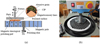 |
Fig. 1 Principle and equipment of magnetorheological polishing. |
3 Preparation and polishing test design of Ti6Al4V sample
3.1 Brief analysis of forming material equipment, parameters, and surface topography
Using SLM-125HL selective laser melting system by SLM Solution Company to manufacture samples, as shown in Figure 2. Using 400 w single-lens IPG fiber laser, the maximum molding size is 125 × 125 × 125 mm. The chemical composition of Ti6Al4V spherical powder produced by LPBF solution is shown in Table 2. The size range of the powder was 15–53 µm, and the average particle size is 20 µm, the SEM appearance of the powder is shown in Figure 3a. The shape of the powder was nearly regular spherical, and the surface had less satellite powder, which helped improve the smoothness of the powder-spreading process. The Ti6Al4V powder was placed in a vacuum-drying box (70 ℃ × 2 h) to be dried before sieving and filtering. The purpose of this step was to dry the powder and remove impurities, thereby ensuring the quality and precision of the forming. Argon gas was continuously pumped into the cabin throughout the entire process to ensure the air pressure and temperature stability, and the oxygen content was less than 0.06%. The forming process parameters were determined according to equipment performance, as shown in Table 3.
The size of the formed part was 25 × 25 × 3 mm3. After manufacturing, it was cut off using a wire electrical-discharge machining. The original surface roughness (Ra) was 19–50 µm. After further measurement, the total volume of surface holes prepared this time was 2.86 × 10⁻³ mm3, and the density was 4.3 g/cm3, which was slightly lower than the density of raw material of 4.5 g/cm3. Figure 3b shows that holes existed on the surface of the formed part, accumulation, and melt gap, especially the melt gap and powder adhesion. This finding was due to the existence of a certain temperature gradient between the molten pool and the surrounding powder during melting. This phenomenon resulted in a surface tension gradient, which in turn generated induced the fluctuation of the metal liquid level in the molten pool, blocking the liquid level to form small balls. The spheroidisation further formed gaps. The liquid metal cannot enter the gap, producing to holes and weld-path gaps in the forming layer. Consequently, the surface quality of the formed parts was poor, thereby affecting the use and reflecting the necessity of further polishing.
Chemical composition of Ti6Al4V powder (in weight percent, wt%).
LPBF process parameters.
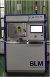 |
Fig. 2 SIM-125HL metal 3D printer. |
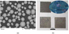 |
Fig. 3 Ti6Al4V powder and formed parts. |
3.2 Polishing test design
In the magnetorheological polishing process, polishing pressure, abrasive particle size, and polishing time were the main factors affecting the final polishing quality and material-removal rate. To explore the influence of the above process parameters on the parts’ surface, the LPBF additive Ti6Al4V samples were polished by single-factor test method. The test parameters and conditions are shown in Table 4. The main components of the water-based magnetorheological polishing solution were 40% vol carbonyl iron powder, 3% vol alumina abrasive, 55% vol deionised water, and 2% additives. To ensure the polishing effect, the magnetorheological polishing fluid was stirred and dispersed by ultrasonic vibration at a high speed for more than 30 min before polishing, so that carbonyl iron powder and abrasive particles can be stably and uniformly distributed in the carrier fluid, thereby preventing particle agglomeration from causing scratches and defects on the polished surface. The surface roughness of the samples before and after polishing was measured using a Mahr-XR20 roughness meter, three measurement points were taken and the average value was calculated as the experimental result, and a KH1300 ultra-depth-of-field microscope was used to observe the surface morphology of the samples.
Single factor experiment of inhead type of magnetorheological polishing.
4 Results and discussion
4.1 Effect of wear particle size on surface roughness and material-removal rate
The polishing speed was 50 rpm, the polishing time was 1 h and the polishing pressure was 10 N. As shown in Figure 4, when the abrasive particle size was 20 µm, the surface-roughness value decreased to 333.4 nm, and the abrasive-particle size decreased continuously. With decreased abrasive-particle size from 10 µm to 5 µm, the surface-roughness value decreased from 308.1 nm to 263.5 nm, and the difference was 44.6 nm. When the particle size was 3 µm, the polishing surface roughness was 273.3 nm. Compared with 5 µm, the surface-roughness value increased and the surface quality decreased because when the size of abrasive particles was large, the polishing force of abrasive particles on the sample surface was large. The roughness of the sample surface decreased obviously at the beginning of polishing, and the defects on the surface of the sample were removed. At the same time, the abrasive particles scratched the surface of the sample, leaving obvious scratches. When the particle size was smaller, the polishing pressure was also smaller, and the surface of the sample was not obviously scratched, but the original defects of the sample surface were not removed obviously. Consequently, the surface-roughness value slowly declined.
When the particle size was 20, 10, 5, 3 µm, the material-removal rate was 4.19, 3.59, 3.29 and 2.88 nm/min, respectively, and the adjacent difference was 0.6, 0.3, and 0.41 nm/min, respectively. Obviously, the size of wear particle greatly influenced the material-removal rate. In the mechanical removal mechanism of magnetorheological polishing, under certain load conditions, the abrasive particles were rubbed and plowed to remove the material. A greater abrasive-particle diameter corresponded with a greater height of the abrasive particles exposed on the magnetorheological polishing pad. A deeper pressure corresponded with more obvious ploughing effect and higher material-removal rate. As the size of the abrasive particle decreased, the height of the abrasive particle decreased, and the material-removal rate was reduced.
Combined with the microappearance in Figure 5, when the wear particle size was large (Fig. 5a), some original defects on the sample surface were obviously removed. No obvious continuous melting-path defect was found, and the melting-path area was small. Signs of convergence were found (Figs. 5b,5c). However, the surface of the sample with large grain size had obvious scratches, whereas that with small grain size had no scratches. The original defects on the surface of the sample were not effectively removed, and internal spheroidising particles were also clearly visible (shown in Fig. 5d).
Based on the above analysis, we can conclude that under other process parameters, with decreased particle size, the polishing pressure decreased and the material-removal rate decreased. Under the condition of small abrasive-particle size, a better polishing effect can be obtained by improving the surface quality before polishing and prolonging the processing time.
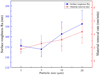 |
Fig. 4 Surface roughness (Ra) and material-removal rate under different abrasive particle sizes. |
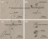 |
Fig. 5 Microscopic appearance under different abrasive particle sizes: (a) 20 µm, (b) 10 µm, (c) 5 µm, (d) 3 µm. |
4.2 Effect of polishing pressure on surface roughness and material-removal rate
The polishing speed was 50 rpm, the polishing time was 1 h and the abrasive particle size was 20 µm, with increased polishing pressure from 5 N to 15 N. As shown in Figure 6, the sample surface-roughness values were 291.8, 262.5, and 249.8 nm, and the adjacent difference was 29.3 and 12.7 nm, respectively. The surface-roughness value decreased to some extent with increased polishing pressure to 20 N. The surface-roughness value was 142.8 nm, which was about 107 nm lower than that of 15 N, and the rate of decrease was about 42.8%. The surface quality obviously improved, but when the polishing pressure was 25 N, the difference between the surface roughness and the former was not large, but it still increased because the polishing pressure was too large to lead to poor polishing effect. In a certain range, with increased the polishing pressure, the rubbing and ploughing of the abrasive grains on the surface of the sample increased, the grinding effect was enhanced, and the surface-roughness value initially decreased and then increased.
When the polishing pressure was 5 N, the material-removal rate was 1.19 nm/min. With increased polishing pressure, the material-removal rate also increased. When the polishing pressure was 25 N, the material-removal rate was 8.68 nm/min, which was 2.99 nm/min higher than 5.69 nm/min at 20 N, the increase rate was 52.5%. A greater polishing pressure induced deeper pressing of the abrasive onto the sample surface, which increased the cutting and material-removal rate.
Combined with the microscopic appearance in Figure 7, when the polishing pressure was small (shown in Figs. 7a,7b,7c), the abrasive particles were primarily scratched and elastic deformation occurred to remove surface defects. Although the polishing effect was relatively limited, it did not cause obvious scratches. With increased polishing pressure, the abrasive particles entered the plough cutting state. Owing to the pressing of the abrasive particles, the surface materials of the sample were extruded on both sides in contact with the abrasive particles to form a certain bulge. When the damage limit of the material was reached, it broke and formed obvious scratches. This was very evident in Figures 7d,7e. On one hand, the original defects on the surface can be removed; on the other hand, some abrasive particles formed deep scratches, resulting in surface damage. Consequently, the polishing quality decreased.
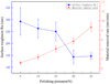 |
Fig. 6 Surface roughness (Ra) and material-removal rate under different polishing forces. |
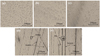 |
Fig. 7 Microscopic appearance under different polishing forces: (a) 5 N, (b) 10 N, (c) 15 N, (d) 20 N, (e) 25 N. |
4.3 Effect of polishing time on surface roughness and material-removal rate
As shown in Figure 8, the polishing speed was 50 rpm, the polishing pressure was 5 N and the abrasive particle size was 5 µm, with increased polishing time, the surface-roughness value after polishing continued to decline. At the initial stage of polishing, the difference in surface roughness obviously changed. After 2 h of polishing, the difference value was 207.9 nm, and the decline rate was 56%. After 4 h of polishing, the surface roughness tended to be flat. We observed the corresponding material-removal rate under different polishing times. When the polishing time was 0.5 h, the maximum material-removal rate was 3.04 nm/min. With continuously extended polishing time, the material-removal rate decreased. After polishing for 2 h, the material-removal rate decreased to 1.39 nm/min. When it was further extended to 4.5 h, the material-removal rate was only 0.29 nm/min. At the initial stage of polishing, owing to the local overheated metal powder and slag falling on both sides of the melting path during the additive moulding of the sample itself and some unmelted powder, it was easy to be polished and removed. Thus, the material-removal rate was high in the early stage. With extended polishing time, after some defects on the surface were easily and continuously removed, the moulding quality of the lower matrix area and the removal difficulty both increased. This phenomenon caused a decrease in material-removal rate. These findings indicated the necessity of the current research on the magnetorheological polishing of additive molded parts.
By observing the microscopic appearance in Figure 9, we found that at the initial stage of polishing, the main defects on the surface of the sample were characterised by discontinuous and irregular weld path gap (Figs. 9a,9b). Spheroidisation phenomenon was clearly visible at the bottom of the weld path. With continuous polishing (shown in Figs. 9c,9d,9e), the irregular weld-path defects on the surface began to converge and become quasi-circular, that is, weld-path defects were further removed and reduced. Furthermore, with continuous polishing as shown in Figures 9f,9g, it gradually reached the bottom end of the melting channel, exposing the small holes between the lower ends of the powder layer. At this time, when polishing was continued, “comet-tail” defects were generated. Unidirectional fine grooves formed with the pore as the initial direction primarily because small polishing-abrasive particles easily accumulated at the edge of the hole, resulting in the different material-removal rates between the hole area and the areas on both sides of the scratch. The comet-tail defects then occurred in the original defect area (Fig. 9h). Therefore, in the polishing process, we should pay attention to appropriately reducing the loading pressure, prevent rapid removal, and obtain the ideal polishing surface whilst avoiding the “comet-tail” defect. When polished for 4.5 h as shown in Figure 9i, the surface defects typical of the Ti6Al4V by LPBF additive molding had been completely removed, and extending the polishing time to 5 h (Fig. 9j) showed no sign of further improvement in the surface quality.
It can be seen from the above analysis that, different from traditional castings or forgings, the internal defects of LPBF Ti6Al4V parts include pores, poor fusion and cracking, and the hole morphology is regular spherical, and the distribution is random. The fusion on both sides of the weld channel is poor and irregular. Therefore, it is very necessary to carry out magnetorheological polishing to explore the evolution law of surface material removal.
Magnetorheological polishing the surface quality of Ti6Al4V was affected by several process parameters, such as abrasive particle size, polishing pressure, and polishing time. The optimal process was achieved using a 5 μm Al2O3 abrasive particle size and polishing pressure of 5 N for 4.5 h, surface roughness decreased from the initial 368 ± 13.2 nm to 19.77 ± 1.14 nm, and the surface became smooth. The comparison before and after polishing is shown in Figure 10.
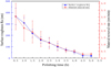 |
Fig. 8 Surface roughness (Ra) and material-removal rate under different polishing times. |
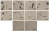 |
Fig. 9 Microscopic appearance under different polishing times: (a) 0.5 h, (b) 1 h, (c) 1.5 h, (d) 2 h, (e) 2.5 h, (a) 3 h, (b) 3.5 h, (c) 4 h, (d) 4.5 h, (e) 5 h. |
 |
Fig. 10 Comparison before and after polishing: (a) before, (b) after. |
5 Conclusion
In this paper, magnetorheological polishing experiments were carried out on LPBF Ti6Al4V samples, and the influence of process parameters (abrasive particle size, polishing pressure, polishing time) on the surface roughness and material removal rate of the samples in the magnetorheological polishing technology was studied. The magnetorheological polishing technology can effectively remove the typical surface defects of LPBF additively formed Ti6Al4V, and meet the requirements of medical implant surface roughness below Ra 0.1 μm. It provides a new way for surface treatment of additive molding pieces of medical Ti alloy.
The present research in this paper can be used in academic research and industry, but it also has some limitations, which are also the focus of future work.
At present, the removal efficiency of materials by magnetorheological polishing is low, and ultrasonic technology can be introduced in the future to form ultrasonic magnetorheological compound polishing technology to study the effect of ultrasonic frequency on material removal.
Declaration of competing interest
No potential conflict of interest was reported by the authors.
Acknowledgments
This project was supported by the Natural Science Foundation of Fujian Province (Grant No. 2020J01874), the Fujian Province Industry-University-Research Joint Innovation Project (Grant No. 2020H6028) and the Program for Innovative Research Team in Science and Technology in Fujian Province University ([2020] No. 12).
References
- V.K. Meena, P. Kumar, P. Kalra, R.K. Sinha, Additive manufacturing for metallic spinal implants: a systematic review, Ann. 3D Printed Med. 3, 100021 (2021) [CrossRef] [Google Scholar]
- P. Moghimian, T. Poirié, M. Habibnejad-Korayem, et al., Metal powders in additive manufacturing: a review on reusability and recyclability of common titanium, nickel and aluminum alloys, Addit. Manufactur. 43, 102017 (2021) [CrossRef] [Google Scholar]
- A. Nouri, A. Rohani Shirvan, Y. Li, C. Wen, Additive manufacturing of metallic and polymeric load-bearing biomaterials using laser powder bed fusion: a review, J. Mater. Sci. Technol. 94, 196–215 (2021) [CrossRef] [Google Scholar]
- A. Ostovari Moghaddam, N.A. Shaburova, M.N. Samodurova, A. Abdollahzadeh, E.A. Trofimov, Additive manufacturing of high entropy alloys: A practical review, J. Mater. Sci. Technol. 77, 131–162 (2021) [CrossRef] [Google Scholar]
- M. Ansari, E. Jabari, E. Toyserkani, Opportunities and challenges in additive manufacturing of functionally graded metallic materials via powder-fed laser directed energy deposition: a review, J. Mater. Process. Technol. 294, 117117 (2021) [CrossRef] [Google Scholar]
- G. Gong, J. Ye, Y. Chi, et al., Research status of laser additive manufacturing for metal: a review, J. Mater. Res. Technol. 15, 855–884 (2021) [CrossRef] [Google Scholar]
- K. Ishfaq, M. Abdullah, M.A. Mahmood, A state-of-the-art direct metal laser sintering of Ti6Al4V and AlSi10Mg alloys: surface roughness, tensile strength, fatigue strength and microstructure, Optics Laser Technol. 143, 107366 (2021) [CrossRef] [Google Scholar]
- A.K. Singla, M. Banerjee, A. Sharma, et al., Selective laser melting of Ti6Al4V alloy: process parameters, defects and post-treatments, J. Manufactur. Process. 64, 161–187 (2021) [CrossRef] [Google Scholar]
- J.A. Tamayo, M. Riascos, C.A. Vargas, L.M. Baena, Additive manufacturing of Ti6Al4V alloy via electron beam melting for the development of implants for the biomedical industry, Heliyon 7, e06892 (2021) [CrossRef] [PubMed] [Google Scholar]
- H.S. Park, M.J. Ansari, Estimation of residual stress and deformation in selective laser melting of Ti6Al4V alloy, Proc. CIRP 93, 44–49 (2020) [CrossRef] [Google Scholar]
- T. Rautio, A. Hamada, J. Mäkikangas, M. Jaskari, A. Järvenpää, Laser welding of selective laser melted Ti6Al4V: Microstructure and mechanical properties, Mater. Today: Proc. 28, 907–911 (2020) [CrossRef] [Google Scholar]
- I.T. 150, Surgical implants. Partial and complete hip prostheses. Part 2: Articulating surfaces made of metals, ceramics and plastics. 2011 pp. 12P.;A14 [Google Scholar]
- B.S. Institution, Non-active surgical implants – joint replacement implants – specific requirements for knee-joint replacement implants (ISO 21536), 2009 [Google Scholar]
- L. Baotai Group Co., I.o.N.M.T.a. Economics, Titanium and titanium alloy processing materials for surgical implants. General Administration of Quality Supervision Inspection and Quarantine of the People’s Republic of China, National standardization and Administration Committee of China (2017), pp. 20 [Google Scholar]
- T.M.D.Q.S.a.I. Center, C.S.F.a.D.A.M.D.T.E. Center, Passive surgical implants - General requirements (State Food and Drug Administration, 2016), pp. 1–16 [Google Scholar]
- A.D. Baghi, S. Nafisi, R. Hashemi, H. Ebendorff-Heidepriem, R. Ghomashchi, Effective post processing of SLM fabricated Ti-6Al-4 V alloy: machining vs thermal treatment, J. Manufactur. Process. 68, 1031–1046 (2021) [CrossRef] [Google Scholar]
- S.H. Riza, Comprehensive Materials Processing (Elsevier, 2014) [Google Scholar]
- Y. Eyzat, M. Chemkhi, Q. Portella, J. Gardan, J. Remond, D. Retraint, Characterization and mechanical properties of As-Built SLM Ti-6Al-4V subjected to surface mechanical post-treatment, Proc. CIRP 81, 1225–1229 (2019) [CrossRef] [Google Scholar]
- P.R. da Costa, M. Sardinha, L. Reis, M. Freitas, M. Fonte, Ultrasonic fatigue testing in as-built and polished Ti6Al4V alloy manufactured by SLM, Forces Mech. 4, 100024 (2021) [CrossRef] [Google Scholar]
- M.A. Obeidi, E. McCarthy, B. O’Connell, I.U. Ahad, D. Brabazon, Laser polishing of additive manufactured 316L stainless steel synthesized by selective laser melting, Materials (2019) [Google Scholar]
- M.A. Obeidi, A. Mussatto, M.N. Dogu, et al., Laser surface polishing of Ti-6Al-4V parts manufactured by laser powder bed fusion, Surf. Coat. Technol. 434, 128179 (2022) [CrossRef] [Google Scholar]
- A. Balyakin, E. Zhuchenko, E. Nosova, Study of heat treatment impact on the surface defects appearance on samples obtained by selective laser melting of Ti-6Al-4V during chemical polishing, Mater. Today: Proc. 19 (2019) [Google Scholar]
- C. Zhao, N. Qu, X. Tang, Electrochemical mechanical polishing of internal holes created by selective laser melting, J. Manufactur. Process. 64, 1544–1562 (2021) [CrossRef] [Google Scholar]
- A.K. Bastola, M. Hossain, The shape – morphing performance of magnetoactive soft materials, Mater. Des. 211, 110172 (2021) [CrossRef] [Google Scholar]
- S. Kumar, R. Sehgal, M.F. Wani, M.D. Sharma, Stabilization and tribological properties of magnetorheological (MR) fluids: a review, J. Magn. Magn. Mater. 538, 168295 (2021) [CrossRef] [Google Scholar]
- Z. Xia, F. Fang, E. Ahearne, M. Tao, Advances in polishing of optical freeform surfaces: a review, J. Mater. Process. Technol. 286, 116828 (2020) [CrossRef] [Google Scholar]
- M.N. Aruna, M.R. Rahman, S. Joladarashi, H. Kumar, P. Devadas Bhat, Influence of different fumed silica as thixotropic additive on carbonyl particles magnetorheological fluids for sedimentation effects, J. Magn. Magn. Mater. 529, 167910 (2021) [CrossRef] [Google Scholar]
- B. Gopinath, G.K. Sathishkumar, P. Karthik, et al., A systematic study of the impact of additives on structural and mechanical properties of magnetorheological fluids, Mater. Today: Proc. 37, 1721–1728 (2021) [CrossRef] [Google Scholar]
- Q. Luo, Y. Wang, H. Liu, J. Wang, Y. Gan, T. Li, Static response analysis of shallow spherical shell under local support of magnetorheological fluid (MRF), Thin-Walled Struct. 169, 108470 (2021) [CrossRef] [Google Scholar]
- G. Wang, J. Geng, X. Qi, et al., Rheological performances and enhanced sedimentation stability of mesoporous Fe3O4 nanospheres in magnetorheological fluid, J. Mol. Liquids 336, 116389 (2021) [CrossRef] [Google Scholar]
- T. Xuan, J. Li, B. Li, W. Fan, Effects of the non-uniform magnetic field on the shear stress and the microstructure of magnetorheological fluid, J. Magn. Magn. Mater. 535, 168066 (2021) [CrossRef] [Google Scholar]
- C. Bingsan, Z. Cheng, B. Zhongyu, L. Chunyu, H. Dicheng, Enhancement effect of nonferromagnetic particles on the viscosity of magnetorheological fluid under a dynamic magnetic field, Funct. Mater. Lett. 14, 6 (2021) [Google Scholar]
- Z. Xie, N. Shen, W. Zhu, W. Tian, L. Hao, Theoretical and experimental investigation on the influences of misalignment on the lubrication performances and lubrication regimes transition of water lubricated bearing, Mech. Syst. Signal Proces. 149, 107211 (2021) [CrossRef] [Google Scholar]
- Z. Xie, W. Zhu, Theoretical and experimental exploration on the micro asperity contact load ratios and lubrication regimes transition for water-lubricated stern tube bearing, Tribol. Int. 164, 107105 (2021) [CrossRef] [Google Scholar]
- G. Wang, W. Wang, Y. Zhang, et al., Study on micro-plastic behavior and tribological characteristics of granular materials in friction process, Ind. Lubric. Tribol. 73, 1098–1104 (2021) [CrossRef] [Google Scholar]
- Q. Zhang, B. Wu, R. Song, H. Song, J. Zhang, X. Hu, Preparation, characterization and tribological properties of polyalphaolefin with magnetic reduced graphene oxide/Fe3O4 , Tribol. Int. 141, 105952 (2020) [CrossRef] [Google Scholar]
- H. Kansal, A.K. Singh, V. Grover, Magnetorheological nano-finishing of diamagnetic material using permanent magnets tool, Precis. Eng. 51, 30–39 (2018) [CrossRef] [Google Scholar]
- S.K. Paswan, A.K. Singh, Investigation of optimized parameters for magnetorheological finishing the internal surface of the cast-iron cylindrical molds, Arab. J. Sci. Eng. 46, 2147–2164 (2021) [CrossRef] [Google Scholar]
- A. Farshid, B. Hassan, Y. Pouria, Effect of abrasive particle morphology along with other influencing parameters in magnetic abrasive finishing process, Mech. Ind. 22, 15 (2021) [CrossRef] [EDP Sciences] [Google Scholar]
- G. Parameswari, V.K. Jain, J. Ramkumar, L. Nagdeve, Experimental investigations into nanofinishing of Ti6Al4V flat disc using magnetorheological finishing process, Int. J. Adv. Manufactur. Technol. 100, 1055–1065 (2019) [CrossRef] [Google Scholar]
- A. Barman, M. Das, Toolpath generation and finishing of bio-titanium alloy using novel polishing tool in MFAF process, Int. J. Adv. Manufactur. Technol. 100, 1123–1135 (2019) [CrossRef] [Google Scholar]
- W. Kordonski, S. Gorodkin, The behavior of a magnetorheological (MR) fluid under compressive deformation, J. Rheol. 60 (2016) [Google Scholar]
- Z. Xie, W. Zhu, An investigation on the lubrication characteristics of floating ring bearing with consideration of multi-coupling factors, Mech. Syst. Signal Process. 162, 108086 (2022) [CrossRef] [Google Scholar]
Cite this article as: Z. Bao, B. Chen, S. Na, Y. Xu, S. Hung, Evolution of material removal in the magnetorheological polishing of Ti6Al4V by laser power bed fusion, Mechanics & Industry 23, 12 (2022)
All Tables
All Figures
|
Fig. 1 Principle and equipment of magnetorheological polishing. |
| In the text | |
|
Fig. 2 SIM-125HL metal 3D printer. |
| In the text | |
|
Fig. 3 Ti6Al4V powder and formed parts. |
| In the text | |
|
Fig. 4 Surface roughness (Ra) and material-removal rate under different abrasive particle sizes. |
| In the text | |
|
Fig. 5 Microscopic appearance under different abrasive particle sizes: (a) 20 µm, (b) 10 µm, (c) 5 µm, (d) 3 µm. |
| In the text | |
|
Fig. 6 Surface roughness (Ra) and material-removal rate under different polishing forces. |
| In the text | |
|
Fig. 7 Microscopic appearance under different polishing forces: (a) 5 N, (b) 10 N, (c) 15 N, (d) 20 N, (e) 25 N. |
| In the text | |
|
Fig. 8 Surface roughness (Ra) and material-removal rate under different polishing times. |
| In the text | |
|
Fig. 9 Microscopic appearance under different polishing times: (a) 0.5 h, (b) 1 h, (c) 1.5 h, (d) 2 h, (e) 2.5 h, (a) 3 h, (b) 3.5 h, (c) 4 h, (d) 4.5 h, (e) 5 h. |
| In the text | |
|
Fig. 10 Comparison before and after polishing: (a) before, (b) after. |
| In the text | |
Current usage metrics show cumulative count of Article Views (full-text article views including HTML views, PDF and ePub downloads, according to the available data) and Abstracts Views on Vision4Press platform.
Data correspond to usage on the plateform after 2015. The current usage metrics is available 48-96 hours after online publication and is updated daily on week days.
Initial download of the metrics may take a while.