| Issue |
Mechanics & Industry
Volume 27, 2026
|
|
|---|---|---|
| Article Number | 16 | |
| Number of page(s) | 9 | |
| DOI | https://doi.org/10.1051/meca/2026013 | |
| Published online | 21 April 2026 | |
Original Article
Multi-objective optimization of free-form texture shape formed by Bezier curves for mechanical seals
1
School of Mechanical Engineering, Jiangsu University of Technology, 1801 Zhongwu Rd., Changzhou, Jiangsu 213001, PR China
2
Changzhou Yuexin Transmission System Co., Ltd, Changzhou 213001, PR China
* e-mail: This email address is being protected from spambots. You need JavaScript enabled to view it.
Received:
31
October
2025
Accepted:
4
March
2026
Abstract
This study focuses on enhancing the tribological performance (reducing friction and wear) and sealing efficacy of mechanical seals through the multi-objective optimization of surface textures. A novel texture model is established that features free-form shapes precisely controlled by Bezier curves, thereby enabling significant geometric flexibility. The optimal texture configurations are determined using a dedicated multi-objective optimization methodology. For comparative analysis, a conventional circular texture model with variable radii and positioning is also developed and subjected to the same optimization process. Specimens incorporating the optimized free-form and circular textures were fabricated and rigorously tested under experimental conditions. The experimental findings are in good agreement with the theoretical predictions and fall within acceptable error margins. Critically, the results indicate that, in most cases examined, the optimized free-form textures deliver a superior combination of performance attributes—specifically, higher load-carrying capacity and lower leakage rates—compared with the optimized circular textures.
Key words: Mechanical seal / multi-objective optimization / surface texture / load-carrying capacity
© C. Ding et al., Published by EDP Sciences, 2026
 This is an Open Access article distributed under the terms of the Creative Commons Attribution License (https://creativecommons.org/licenses/by/4.0), which permits unrestricted use, distribution, and reproduction in any medium, provided the original work is properly cited.
1 Introduction
Surface texturing is a widely used method in tribology and has also attracted considerable attention in mechanical seals [1–4]. Many studies on mechanical seals have focused on reducing friction/wear and leakage. However, surface textures with low friction or high opening force often exhibit high leakage [5–7]. This is because the generated opening force increases the clearance of the seal rings, thereby increasing leakage [7]. Siripuram and Stephens [8] found that, for positive asperity, the maximum leakage occurs when the asperity area fraction is 0.2, at which the coefficient of friction is minimum; for negative asperity, leakage increases as the coefficient of friction decreases. To address the trade-off between tribological performance and leakage properties, Wang et al. [6,9] developed a multi-objective optimization approach to optimize texture shape. They obtained optimal textures with “V” shapes, which differ from those obtained by single-objective optimization [10,11]. These studies inform the optimization of the texture of mechanical components with two or more key performance parameters.
In the multi-objective optimization of surface texture, the finite difference method (FDM) is often used because it is easier to combine with the multi-objective optimization algorithm than the finite volume method (FVM) and finite element method (FEM), which are powerful methods for solving the issue of discontinuous film thickness [12–15]. FDM requires special treatment in regions of discontinuous film thickness. For example, Chen et al. [16] applied an eight-point discrete grid to approximate the film thickness gradient. Ogata et al. [17] proposed an algorithm to determine the equivalent clearance height and the equivalent gradient of the clearance height in regions of discontinuous film thickness in step bearings. In addition, studies based on a simplified energy equation, assuming adiabatic conditions and a constant temperature across the film thickness, indicated that thermal effects significantly alter viscosity in sliding and stepped bearings [18–20]. Khonsari [21–23] summarized the early, important publications on thermal effects in journal bearings and noted that most existing analytical solutions are based on simplified assumptions that are questionable in validity. A review by Sivakumar concluded that thermal effects strongly influence film thickness and pressure and that thermal behaviour is strongly influenced by speed [24,25]. In addition, many researchers [26,27] have pointed out that the temperature difference across the film thickness, known as the “viscosity wedge effect”, has a significant effect on the load-carrying capacity. Therefore, the discontinuity in film thickness and thermal effects are considered in this study to improve simulation accuracy.
In addition, existing studies on texture shape optimization often produce texture shapes with sharp edges because the physical model of the texture is usually built by connecting the points with straight lines, such as the similar chevron shapes with flat fronts [10], the asymmetric “V” shape [9], and the similar water drop shape [28]. In fact, these optimal textures with sharp features perform better in computational tasks. However, machining accuracy at sharp edges is difficult to guarantee, and sharp edges often cause vibration or severe cutting effects on soft materials during experiments, particularly under low-speed, heavy-load operating conditions.
Based on the above analysis, discontinuous film thickness and thermal effects will be incorporated to improve the accuracy of multi-objective optimization; a free-form texture shape model controlled by Bezier curves will be developed to avoid sharp edges; and a circular texture shape with a variable radius and location will be defined for comparison. The optimal shapes are obtained using the elitist non-dominated sorting genetic algorithm (NSGA-II). Meanwhile, the mechanical seal specimens with the optimal textures are prepared and tested experimentally.
2 Multi-objective optimization
2.1 Physical model
The multi-objective optimization of surface texture is a complex and time-consuming problem. To improve the efficiency of this study, a single-texture cell is used as the computational region. The computational region is simplified to a square area with a nondimensional size of 1 × 1. The textures are designed on the surface of the rotating specimen. Figure 1 shows the texture models of a free-form shape and a circular shape. Bezier curves are well-suited to describing features and are widely used in industrial design. It is a method for generating complex, smooth curves from a few control points. Textures connected by Bezier curves can avoid sharp shapes. In this study, there are k(n-1) radial lines with the length of ri (i = 1, 2, . . ., k(n-1)) starting from the center of the computational region, which are uniformly distributed in the circumferential direction. K Bezier curves form the texture, and n endpoints of the radial lines control each Bezier curve. The first Bezier curve is controlled by r1, r2, . . ., rn-1, rn; the second Bezier curve is controlled by rn, rn+1, . . .,r2n-2, r2n-1; and the kth Bezier curve is controlled by r(k-1)n-(k-1), r(k-1)n-(k-1)+1, . . ., rk(n-1), r1. So, the design variables of free-form shape are r1, r2, . . ., rk(n-1). The design variables of the circular dimple are rc and ry, where rc is the radius of the circular dimple, and ry is the y-coordinate of the center point. The x-coordinate is equal to 1/2 due to the periodicity of the dimples in the direction of movement.
The negative dimensionless load-carrying capacity, -W, and the dimensionless leakage rate, Q, are the objectives of the multi-objective optimization and are calculated using the equations presented in the next section. The multi-objective optimization models for free-form shape and circular shape can be expressed as, respectively:
 (1)
(1)
 (2)
(2)
The constraints on the design variables ensure that the surface-texture area ratio does not exceed 0.4. The performance parameters of - W and Q are obtained by solving Reynolds equations. By using a modified equation to redefine the node of the discontinuous regions, the control equation becomes valid for the entire calculation domain, including both continuous and discontinuous regions. This allows the equation to be solved using FDM. A simplified energy equation is employed to modify the control equation to account for thermal effects. Further information can be found in previous publications [29,30].
Multi-objective optimization is performed on the models, including five free-form shapes (k1n7, k2n6, k3n5, k4n4, and k5n3) and the circular dimple. k1n7 indicates that a Bezier curve surrounds the texture boundary; seven control points form each curve. The detailed information is given in Table 1. The values of the geometric parameters and condition parameters used in the simulation are shown in Table 2.
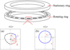 |
Fig. 1 Texture models: (a) free-form shape; (b) circular shape. |
Texture models.
Geometric parameters and condition parameters.
2.2 Optimization results
2.2.1 Multi-objective results
For each model, 30 optimal solutions are obtained. For Model k1n7, Table 3 presents the optimal design and performance parameters. Each optimal shape maximizes load-carrying capacity when the leakage rate is fixed and minimizes the leakage rate when the load-carrying capacity is fixed. That is, optimal shapes can provide the best overall performance. Different optimal shapes cannot be compared. An optimal shape can be selected for practical application, subject to subjective factors. For example, the first optimal shape can be selected if the actual operating condition requires low leakage, because it exhibits low leakage and provides the highest load-carrying capacity under this leakage.
Figure 2 shows the optimization results. The horizontal axis is the optimal leakage rate, and the vertical axis is the optimal load-carrying capacity. As shown in Figure 2, the optimal free-form shapes, except for the k1n7 model, outperform the optimal circular dimple, indicating that free-form shape optimization can extend the advantages of surface texture. They can provide a higher load-carrying capacity than the optimal circular dimple while maintaining a similar leakage rate. Similarly, they can exhibit lower leakage than the optimal circular dimple while maintaining a comparable load-carrying capacity.
As shown in Figure 2, for the textured mechanical seal, a higher dimensionless load-carrying capacity is always associated with a higher dimensionless leakage, and vice versa. Both the areas of the optimal free-form shapes and the circular shapes increase as the performance parameters, namely the dimensionless load-carrying capacity and leakage, increase. This is because a larger area can increase the high-pressure area to some extent, thereby increasing the load-carrying capacity but also reducing the seal dam area, thereby increasing leakage. The optimal free-form shapes have a wider boundary in the downstream area where the high pressure is generated. This means that the high-pressure regions of optimal free-form shapes are larger than those of optimal circular shapes. Therefore, they can provide a higher load-carrying capacity. Note that the optimal shape derived from multiple Bezier curves is always smooth. It is difficult to form an optimal shape with sharp edges. This makes it impossible to produce the optimal shape with complex boundaries such as “V” shape, chevron shape, fish shape, and herringbone grooves. So, the optimal shape may not have pumping and reflow capabilities. They can be considered as variants of regular shapes.
The optimal free-form shapes for model k5n3 typically yield the best performance. Increasing the number of Bezier curves, k, facilitates the determination of optimal shapes with improved performance. However, reducing the number of points in a Bezier curve, n, has almost no adverse effect on the final results. This may be because the Bezier curve can generate a complex, smooth curve with few control points. The neighboring optimal shapes have a higher similarity, so four optimal shapes of the free-form model and four optimal shapes of the circular model, marked by a grey circle in Figure 5, are selected to be further investigated under the condition of covering different value intervals as much as possible. They are designated as a-1, a-2, a-3, a-4, c-1, c-2, c-3, and c-4, respectively. The detailed parameter values are given in Table 4. The symbol a-1 (k2n6-3) means that the optimal form a-1 is the third optimal solution of the k2n6 model.
The optimal solutions for model k1n7.
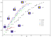 |
Fig. 2 The optimization results. |
The detailed parameter values of selected optimal shapes.
2.2.2 The performance of the optimal textures for different conditions
Figure 3 shows the dimensionless performance parameters as a function of h0/ht, where h0 is the clearance between the stationary and rotating rings and ht is the depth of the surface texture. It shows that optimal free-form shapes retain their advantages. They can provide a higher dimensionless load-carrying capacity than the optimal circular shapes with a similar dimensionless leakage. Meanwhile, they have lower dimensionless leakage than optimal circular shapes, with a similar dimensionless load-carrying capacity. The curves for h0/ht = 0.5 and h0/ht = 1 show that the optimal free-form shapes a-3 and a-4 could produce much larger dimensionless load-carrying capacities than the optimal circular shapes c-3 and c-4. However, the difference decreases for h0/ht = 2.5. This means that as h0/ht increases, the advantages of the optimal free-form shapes become weaker. This may be because h0/ht becomes the dominant factor, more critical than the dimple shape, at larger h0/ht.
A dimensionless number  considering viscosity–temperature, speed, and film thickness is defined to describe the operating condition. Figure 4 shows that optimal free-form shapes outperform optimal circular shapes across different values of λ. The advantage becomes more obvious as λ increases. This means that the optimal shapes obtained via multi-objective optimization under lower λ operating conditions may provide better performance under higher λ operating conditions, thereby simplifying the application of multi-objective optimization to mechanical seals.
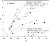 |
Fig. 3 Dimensionless performance parameters for different h0/ht. |
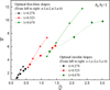 |
Fig. 4 Dimensionless performance parameters for different λ. |
3 Experimental procedure
The stationary specimen is made of sintered graphite, and the rotating specimen is made of 304 stainless steel. Surface textures are fabricated on the rotating specimen’s sliding surface using lithography and electrochemical machining. The specimens are shown in Figure 5.
The tests are carried out using a specialized test rig, and the sealing medium is L-AN46. The inner pressure is set to 0.12 MPa. Experiments are conducted to obtain the leakage rate and the friction coefficient f. Detailed information on the test rig is provided in our previous study [31]. A 30-min running-in period is required to reach steady state. Each experiment is repeated three times to ensure reliability.
For the textured mechanical seal model, using the same specimen size and texture patterns as in the experiments, the COF and dimensional leakage rate are calculated for comparison with the experimental results. In this study, the frictional force F is calculated by:
 (3)
(3)
Then, the COF f can be calculated by  , where W is the dimensional load-carrying capacity.
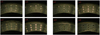 |
Fig. 5 Images of the textured specimens. |
4 Results and discussions
4.1 Comparison of theoretical results and experimental results
A dimensionless parameter accounting for speed and load has been defined in reference [29]. However, the parameter does not adequately characterize the operating condition because it ignores thermal effects. Figure 6 shows the COF and temperature difference for textureless specimens under two operating conditions. Each working condition is repeated three times. According to the dimensionless parameter in reference [29], the two conditions are treated as one dimensionless parameter. As shown in Figure 6, the COFs are similar across experiments. However, there is a clear difference in the temperature rise for the two conditions. This indicates that the lubricant viscosity under the two operating conditions has changed significantly. In order to improve the accuracy, a dimensionless number  is defined to describe the operating condition, taking into account the temperature, rotational speed, load, and specimen size. For experiments, W is the applied load. Two loads, 50 and 100 N, and three rotational speeds, 2000, 4000, and 6000 rpm, are applied in this study.
Figure 7 compares the theoretical and experimental results for the optimal shapes. The horizontal axis is the dimensionless leakage rate, and the vertical axis is the dimensionless load-carrying capacity. It should be noted that it is more intuitive to compare the combination performance of the textured specimens by the drawing method of Figure 7. However, the theoretical–experimental errors for COF and the leakage rate are shown simultaneously. As a result, the combination errors appear severe. As shown in Figure 7, the experimental results and theoretical results are very different in value, especially for κ = 1 × 10⁻⁵, although most of the optimal free-form shapes (a-2, a-3, and a-4) show better combination performance in experiments than the optimal circular shapes, which is basically consistent with the theoretical results in this regard. For larger κ (high speed or low load), the experimental leakage rates exceed the theoretical leakage rates. A possible reason is that during occasional unstable operation, such as vibration from asperity contact in some cases, leakage increases substantially, thereby causing the observed leakage rates to exceed the actual values. At lower κ (low speed or high load), the experimental leakage rates are lower than the theoretical rates. However, the experimental COFs are larger than the theoretical COFs, except for specimen a-1. One possible reason is that when two surfaces are pressed together, a large force is often required to separate them or initiate sliding, which may result in a larger experimental COF.
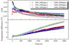 |
Fig. 6 COF and temperature difference of specimens without textures. |
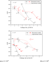 |
Fig. 7 Comparison of theoretical results and experimental results. (a) κ = 1 × 10⁻⁶. (b) κ = 1 × 10⁻⁵. |
4.2 Experimental results for different conditions
Figure 8 shows the variations of the experimental results of c-1 and a-1 versus the dimensionless number κ. As shown in Figure 8, the COFs of c-1 and a-1 decrease with increasing κ. The values of COFs are relatively close; a-1 shows a lower COF than c-1 only at two higher κ conditions. Their leakage rates increase with κ. This is because, under higher-speed conditions, the centrifugal force of the seal medium in the seal gap increases, resulting in greater leakage. At lower loads, the lubricating film is slightly squeezed, and a thicker oil film is easily formed. This tends to cause more seal medium to leak out of the seal chamber.
Figure 9 shows the variations of the experimental results of c-2 and a-2 versus the dimensionless number κ. As shown in Figure 9, the COFs of c-2 and a-2 decrease with increasing κ, as in Figure 8; their COFs are very close. The reduction in friction is not evident for a-1 and a-2. As we can see, the shapes of a-1 and a-2 are very close to ellipses. Zhang et al. [32] obtained an elliptically textured surface using a genetic algorithm and conducted experiments to verify its superiority in reducing friction compared with a circular surface. From this perspective, it can be concluded that the shapes of a-1 and a-2 are obtained by multi-objective optimization primarily because they control leakage. This assumption is confirmed by experiments: in Figures 8 and 9, a-1 and a-2 typically exhibit lower leakage rates than c-1 and c-2, respectively.
Figure 10 shows the variation of the experimental results of c-3 and a-3 versus the dimensionless number κ. The results are similar to those of Figures 8 and 9. The COFs of a-3 and c-3 decrease, and the leakages increase as κ increases. For the lower κ, a-3 has an obviously lower COF than c-3, but its leakage rate is very close to that of c-3. For the higher κ, the friction reduction effect of a-3 disappears, while it even increases the leakage to some extent when 1.9 × 10⁻⁵<κ<3.1 × 10⁻⁵. The conclusion is not consistent with the theoretical results. One possible reason is that the theoretical research is conducted under a constant film thickness. However, the lubrication condition during the test is complex and may change with time. It is not easy to obtain experimental results that are consistently in good agreement with theoretical results. However, three experiments show that a-3 does not yield better combination performance than c-3 for 1.9 × 10⁻⁵<κ<3.1 × 10⁻⁵. This phenomenon provides more accurate guidance for the practical application of multi-objective optimization on mechanical seals.
Figure 11 shows the variation of the experimental results of c-4 and a-4 versus the dimensionless number κ. It differs from the results shown in Figures 8, 9, and 10. The COFs of a-4 and c-4 increase with the increase of κ in most cases. It can be inferred that the experiments are in the hydrodynamic lubrication regime. For all the values of κ studied, a-4 has an obviously lower COF than c-4, but its leakage rate is higher than c-4, except for κ = 4.4 × 10⁻⁵. This means that a-4 is a better choice for the condition with strict requirements for low friction but low requirements for leakage. As shown in Figures 8 and 11, from a-1 to a-4 and from c-1 to c-4, the COF decreases, whereas the leakage rate increases overall. Meanwhile, the optimal free-form shapes exhibit a lower COF or leakage rate than the optimal circular shapes in most cases. In this respect, the experimental results are generally consistent with the theoretical results.
Based on the analysis of the above figures, it can be concluded that optimal free-form texture shapes generally achieve better combination performance than optimal circular textures. The reason is that the free-form texture modeling method has more degrees of freedom and thus encompasses the circular texture model. It is more conducive to exploiting the advantages of the surface texture.
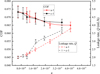 |
Fig. 8 Variations of experimental results of c-1 and a-1 versus dimensionless number κ. |
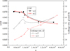 |
Fig. 9 Variations of experimental results of c-2 and a-2 versus dimensionless number κ. |
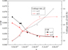 |
Fig. 10 Variations of experimental results of c-3 and a-3 versus dimensionless number κ. |
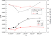 |
Fig. 11 Variations of experimental results of c-4 and a-4 versus dimensionless number κ. |
5 Conclusions
In this study, a modified lubrication model considering film discontinuity and viscosity-thermal effects and a free-form texture shape model controlled by Bezier curves were established. A set of optimal free-form shapes and a set of optimal circular shapes were obtained via multi-objective optimization. A series of experiments was conducted by constructing specimens from the optimal textures. The experimental results are in agreement with the theoretical results. The main conclusions are the following:
The optimal free-form textures show higher load-carrying capacities or lower leakage rates than the optimal circular dimples in most cases in simulation and experiments.
The friction reduction effect is not obvious for a-1 and a-2, but the ability to control leakage is strong.
The optimal shapes of a-3 and a-4 show obviously lower COF than c-3 and c-4, respectively, but their leakage rate is very close to that of c-3 and c-4.
The optimal shape of a-4 is a better choice where there are strict requirements for low friction but low requirements for leakage.
In conclusion, it is suggested that the design schemes for optimal free-form shapes be applied to textured mechanical seals rather than conventional textures to achieve better overall performance because the modeling method for free-form textures essentially encompasses the circular texture model. It is more conducive to exploiting the advantages of surface texture.
Funding
This research received no external funding.
Conflicts of interest
The authors declare no conflict of interest.
Data availability statement
The dataset is available from the corresponding author upon request.
Author contribution statement
Conceptualization, X.Y.W. and C.D.; methodology, C. D.; software, Y. L.W.; validation, X.Y.W.; investigation, C.D.; data curation, X.Y.W.; writing—original draft preparation, X.Y.W.; writing—review and editing, X.Y.W. and Y.L.W.; visualization, L.L.G.; supervision, Y.L.W. and L.L.G. All authors have read and agreed to the published version of the manuscript.
References
- K. Koki, T. Shigeru, U. Tsuyoshi, The possibility of both low friction and low leakage by surface texture of mechanical seals in blood, Tribol. Lett. 68, 65 (2020) [Google Scholar]
- M. Brase, J. Binder, M. Wangenheim, M. Jonkeren, A generalised method for friction optimisation of surface textured seals by machine learning, Lubricants 12, 20 (2024) [Google Scholar]
- C.J. Hsu, A. Stratmann, S. Medina, G.F. Jacobs, C. Gachot, Does laser surface texturing really have a negative impact on the fatigue lifetime of mechanical components? Friction 9, 1766–1775 (2021) [Google Scholar]
- G. Akshay, J.V. Manuel, S. Jorge, Tribological properties of Ti6Al4V titanium textured surfaces created by laser: effect of dimple density, Lubricants 10, 138 (2022) [Google Scholar]
- Z.Q. Wang, J.B. Xiang, Q. Fu, J.K. Wood Robert, S.C. Wang, Study on the friction performance of textured surface on water hydraulic motor piston pair, Tribol. Transac. 65, 308–320 (2022) [Google Scholar]
- X.Y. Wang, L.P. Shi, W. Huang, X.L. Wang, A multi-objective optimization approach on spiral grooves for gas mechanical seals, J. Tribol. 140, 041701 (2018) [Google Scholar]
- J.J. Sun, C.B. Ma, Q.P. Yu, J.H. Lu, M. Zhou, P.Y. Zhou, Numerical analysis on a new pump-out hydrodynamic mechanical seal, Tribol. Int. 106, 62–70 (2017) [Google Scholar]
- R.B. Siripuram, L.S. Stephens, Effect of deterministic asperity geometry on hydrodynamic lubrication, J. Tribol. 126, 527–534 (2004) [Google Scholar]
- X.Y. Wang, L.P. Shi, Q.W. Dai, W. Huang, X.L. Wang, Multi-objective optimization on dimple shapes for gas face seals, Tribol. Int. 123, 216–223 (2018) [Google Scholar]
- C. Shen, M.M. Khonsari, Texture shape optimization for seal-like parallel surfaces: theory and experiment, Tribol. Transac. 59, 698–706 (2016) [Google Scholar]
- H. Zhang, M. Hua, G.Z. Dong, D.Y. Zhang, G.N. Dong, Optimization of texture shape based on genetic algorithm under unidirectional sliding, Tribol. Int. 115, 222–232 (2017) [Google Scholar]
- M. Dobrica, M. Fillon, Reynolds’ model suitability in simulating Rayleigh step bearing thermohydrodynamic problems, Tribol. Transac. 48, 522–530 (2005) [Google Scholar]
- M.B. Dobrica, M. Fillon, Thermohydrodynamic behavior of a slider pocket bearing, J. Tribol. 128, 312–318 (2006) [Google Scholar]
- B.A. Miller, I. Green, Numerical formulation for the dynamic analysis of spiral-grooved gas face seals, J. Tribol. 123, 395–403 (2001) [Google Scholar]
- B.A. Miller, I. Green, Numerical techniques for computing rotordynamic properties of mechanical gas face seals, J. Tribol. 124, 755–761 (2002) [Google Scholar]
- S.K. Chen, H.C. Chou, Y. Kang, Stability analysis of hydrodynamic bearing with herringbone grooved sleeve, Tribol. Int. 55, 15–28 (2012) [Google Scholar]
- H. Ogata, J. Sugimura, Equivalent clearance model for solving thermohydrodynamic lubrication of slider bearings with steps, J. Tribol. 139, 034503 (2017) [Google Scholar]
- A.A. Raimondi, An adiabatic solution for the finite slider bearing (L/B = 1), ASLE Transac. 9, 283–298 (1966) [Google Scholar]
- M. He, P. Allaire, C.H. Cloud, J. Nicholas, A pressure dam bearing analysis with adiabatic thermal effects, Tribol. Transac. 47, 70–76 (2004) [Google Scholar]
- M.M. Khonsari, A review of thermal effects in hydrodynamic bearings, Part I: slider and thrust bearings, ASLE Transac. 30, 19–25 (1987) [Google Scholar]
- M.M. Khonsari, A review of thermal effects in hydrodynamic bearings. Part II: journal bearings, ASLE Transac. 30, 26–33 (1987) [Google Scholar]
- S. Nagesh, K.N. Seetharamu, Review of thermal, turbulent, and misalignment effects on hydrodynamic, in: Proceedings of the First International Conference on Theoretical, Applied and Experimental Mechanics, Vol. 5, Springer, 2018, p. 303 [Google Scholar]
- W. Zhang, Z. Dai, Y. Liang, Topology optimization of sliding surface texture via discrete variable using sequence approximate integer programming, Struct. Multidiscip. Optim. 68, 210 (2025) [Google Scholar]
- I.S. Koç, İ. Temizer, L. Biancofiore, Multiscale analysis and texture design for hydrodynamically lubricated interfaces with variable viscosity and density liquids, Int. J. Solids Structures 323, 113640 (2025) [Google Scholar]
- Z. Jiang, G. Shi, S. Meng, Research on micro-texture design of tools’ surface by topology optimization on cutting performance, Int. J. Adv. Manufac. Technol. 139, 1–13 (2025) [Google Scholar]
- X.K. Meng, M.M. Khonsari, Viscosity wedge effect of dimpled surfaces considering cavitation effect, Tribol. Int. 122, 58–66 (2018) [Google Scholar]
- J.L. Cui, M. Kaneta, P. Yang, P.R. Yang, The relation between thermal wedge and thermal boundary conditions for the load-carrying capacity of a rectangular pad and a slider with parallel gaps, J. Tribol. 138, 024502 (2016) [Google Scholar]
- Y. Chen, J.H. Zhang, B. Xu, Q. Chao, G. Liu, Multi-objective optimization of micron-scale surface textures for the cylinder/valve plate interface in axial piston pumps, Tribol. Int. 138, 316–329 (2019) [Google Scholar]
- X.Y. Wang, M.M. Khonsari, S.Y. Li, Q.W. Dai, X.L. Wang, Experimental verification of textured mechanical seal designed using multi-objective optimization, Ind. Lubr. Tribol. 71, 766–771 (2019) [Google Scholar]
- X.Y. Wang, D.P. Zhi, C.T. Yu, Y. Chen, A thermo-hydrodynamic lubrication model of a mechanical seal modified by equivalent film thickness, Mech. Ind. 21, 622 (2020) [Google Scholar]
- H. Kong, C. Gu, D. Zhang, Topology optimization of textured journal bearings, Lubricants 13, 251 (2025) [Google Scholar]
- H. Zhang, G.N. Dong, M. Hua, K.S. Chin, Improvement of tribological behaviors by optimizing concave texture shape under reciprocating sliding motion, J. Tribol. 139, 011701 (2017) [Google Scholar]
Cite this article as: C. Ding, Y. Wang, L. Gong, X. Wang, Multi-objective optimization of free-form texture shape formed by Bezier curves for mechanical seals, Mechanics & Industry 27, 16 (2026), https://doi.org/10.1051/meca/2026013
All Tables
All Figures
|
Fig. 1 Texture models: (a) free-form shape; (b) circular shape. |
| In the text | |
|
Fig. 2 The optimization results. |
| In the text | |
|
Fig. 3 Dimensionless performance parameters for different h0/ht. |
| In the text | |
|
Fig. 4 Dimensionless performance parameters for different λ. |
| In the text | |
|
Fig. 5 Images of the textured specimens. |
| In the text | |
|
Fig. 6 COF and temperature difference of specimens without textures. |
| In the text | |
|
Fig. 7 Comparison of theoretical results and experimental results. (a) κ = 1 × 10⁻⁶. (b) κ = 1 × 10⁻⁵. |
| In the text | |
|
Fig. 8 Variations of experimental results of c-1 and a-1 versus dimensionless number κ. |
| In the text | |
|
Fig. 9 Variations of experimental results of c-2 and a-2 versus dimensionless number κ. |
| In the text | |
|
Fig. 10 Variations of experimental results of c-3 and a-3 versus dimensionless number κ. |
| In the text | |
|
Fig. 11 Variations of experimental results of c-4 and a-4 versus dimensionless number κ. |
| In the text | |
Current usage metrics show cumulative count of Article Views (full-text article views including HTML views, PDF and ePub downloads, according to the available data) and Abstracts Views on Vision4Press platform.
Data correspond to usage on the plateform after 2015. The current usage metrics is available 48-96 hours after online publication and is updated daily on week days.
Initial download of the metrics may take a while.