| Issue |
Mechanics & Industry
Volume 27, 2026
Recent advances in vibrations, noise, and their use for machine monitoring
|
|
|---|---|---|
| Article Number | 21 | |
| Number of page(s) | 20 | |
| DOI | https://doi.org/10.1051/meca/2026017 | |
| Published online | 30 April 2026 | |
Original Article
Hydraulic St52 tube end orbital forming: improving forming limits and surface quality and dimensional precision through finite element analysis and experimental validation
1
Mechanical Engineering, Faculty of Technology, Selçuk University, Konya, Turkey
2
Akdı Makine, İnnopark Teknoloji Gelistirme Bölgesi, Konya, Turkey
* e-mail: This email address is being protected from spambots. You need JavaScript enabled to view it.
Received:
2
September
2025
Accepted:
23
March
2026
Abstract
Orbital end forming was applied to thick-walled St52 hydraulic tubes to evaluate the forming limits, process safety and dimensional accuracy under controlled operating conditions. Experiments were conducted at a constant feed rate of 10 mm/s with an expansion ratio of rp/r0 = 1.35 and a flaring angle of 37°, using various pressure and frequency combinations. Forming behaviour was assessed through experimental measurements and finite element analysis, focusing on forming force, equivalent stress, surface quality, roundness, and eccentricity. The average experimental forming force was measured at 3000 N, whereas numerical analysis predicted a maximum vertical force of 5000 N, and the maximum equivalent stress reached 481.25 MPa. This value remained below the ultimate tensile strength of the material (505 MPa), thereby confirming safe forming conditions without material failure. Optimal forming parameters of 4 bar pressure and a frequency of 13 Hz resulted in a 73% improvement in surface quality. Using a 60 HRC DIN X153CrMoV12 steel conical die minimised tool wear and ensured high geometric accuracy. The results demonstrate that the proposed orbital forming process provides a reliable, energy-efficient, and industrially applicable solution for precision end forming of thick-walled hydraulic tubes.
Key words: Orbital tube end forming / energy efficient / sustainability / St52 / FEA
© H. Demirpolat and S. Akdi, Published by EDP Sciences, 2026
 This is an Open Access article distributed under the terms of the Creative Commons Attribution License (https://creativecommons.org/licenses/by/4.0), which permits unrestricted use, distribution, and reproduction in any medium, provided the original work is properly cited.
1 Introduction
Orbital forming of tubes is a specialized manufacturing process used to shape or join tube ends through the application of pressure combined with a controlled orbital motion. This process involves various techniques such as flaring, reducing, increasing, machining, countersinking or forming the tube or tube ends [1]. End forming operations are commonly employed to create joints or specific geometries at the ends of tubes, serving various industries such as plumbing, aviation, automotive, construction, and manufacturing [2]. End forming is important in tube manufacturing for several reasons. One of the main purposes is to make a connection between two tubes. Either by expanding one end to fit the other, or by contracting one end to fit the other. In this way, tubes can be joined together in a simple and safe way to create a continuous flow of liquid or gas. The tube end forming process involves a variety of techniques. Flaring creates a larger opening at the end of the tube, allowing for easy insertion of another tube. Reduction, on the other hand, is used to reduce the diameter of one end of a tube to fit into another tube. Forming techniques are also commonly used to shape tube ends to meet specific requirements. The final shape of the tube is particularly important as it allows the tube to be connected to other components when necessary. This may include fittings, valves or other plumbing accessories. The correct forming and configuration of the tube ends ensures leak proof and efficient, strong and secure connections. Tube hydroforming is indeed a significant advancement in tube end forming technology, offering several advantages over traditional machining methods. Modern tube hydroforming machines provide independent control over axial feeding, internal pressure, and counter pressure, greatly enhancing the forming capabilities of the process. However, despite these advantages, hydroforming presents notable challenges related to dimensional accuracy, surface integrity, and energy consumption. The high pressing forces and pressures required to form tube ends can cause the parts being formed to deform, particularly depending on factors such as material thickness and mechanical properties. This deformation can result in the formed tip failing to meet the required dimensional and surface finish standards. This is especially crucial in applications where accurate dimensional and surface properties are vital, such as in high leak proof fittings. Any deviation from required specifications due to deformation can cause manufacturing defects that affect final product performance and reliability. Moreover, hydroforming can present economic and sustainability challenges due to high pressure and power requirements. Hydroforming and Orbital Forming are two different methods of forming tube ends, each with their own advantages, limitations and applications [3]. Hydroforming is an energy intensive process and requires specialised equipment, which can increase production costs and resource utilisation, potentially hindering economic and sustainability goals. Orbital forming is a process in which a forming tool is rotated around the circumference of the tube end [4]. The metal is gradually deformed by the tool, forming it into the desired shape. The process is at room temperature and can handle steel, aluminium, bronze, copper, stainless steel. However, the orbital tube and tube end forming process may have limitations when used on extremely thick or hard materials. This process offers several advantages in creating precise shapes on tube ends, particularly in softer metals [5]. Orbital forming is an appropriate method for creating simple to medium complexity shapes, especially at the ends of tubes. Although it cannot achieve the same level of complexity as hydroforming, it offers high precision and repeatability, making it ideal for applications where dimensional accuracy is critical [4]. Hydroforming typically requires the use of specific tooling such as hydraulic presses, die sets, and bladder or mandrel systems. Particularly for complex shapes, tooling costs can be significant [2]. Orbital forming, on the other hand, is generally associated with simpler tooling than that used in hydroforming. The forming tool may consist of a rotating head or mandrel, along with fixtures to hold the tube in place. Tooling costs are typically lower. This makes orbital forming more accessible for certain applications. The external inversion of thin-walled tubes has been studied numerically and experimentally. The aim was to re-examine the process mechanics and to gain a better understanding of the deformation modes associated with its formability limits [6]. Venugopal and Davidson [7] evaluated the tube end forming process experimentally. Taguchi method was used to optimize the experiment parameters which die angle, expansion ratio and lubricant. 50-ton capacity hydraulic press was used to forming AlMgSi alloy tube. It was obtained that the die cone angle was the most important factor on expansion value. Venugopal and Kosaraju [8] studied on AlMgSi alloy tube end forming process with different die profiles. The stress, thickness profile and strain were analysed. The rules for expanding and reducing tubes have been derived mainly from accumulated experience and technical data currently available in the specialised literature [9]. Almedia et al. [10] carried out experimental and theoretical studies on the expansion and reduction of thin-walled tubes using a die. It was concluded that friction also has an important role in the overall deformability of tube expansion and reduction and that the successful deformation mode can be significantly influenced by a simple change in lubrication. Rosa et al. [11] studied the internal inversion of thin-walled tempered AlMgSi alloy tubes using a die to establish formability diagrams related to key process parameters. They noted that while wrinkling is mainly controlled by the levels of environmental compressive stresses, cracking is likely to be caused by the accumulation of ductile damage. It has also been established that the formability range is strongly influenced by the frictional boundary conditions. In fact, lubrication plays an important role in the overall success of the die stamping operation. Different forming process on thin-walled tubes were investigated by Wen et al. [12]. They found that elastic deformation was the main factor in tube end forming, with cracks, distortions, wrinkles, buckling, collapse and buckling listed as common machining defects. The effects of mechanical properties of tubes and lubricants were investigated on the flaring process [13]. Also conical flaring process was evaluated with respect to stress and strain characteristics by Kitazawa [14]. Also, Lu [15] studied the tube flaring ratio and tube expansion strain rate theoretically. Yeh developed an analytical theory to accurately predict the relationship between the expansion forming limit and tube thickness, punch stroke and expansion ratio. Pragane et al. [16] experimentally and numerically investigated the efficiency of integrating the expansion of commercial forged tubes with a tapered mandrel in the context of additive manufacturing. Although their formability in additive manufacturing is affected by a dendritic-based microstructure, their performance has shown that tube end forming processes such as tube expansion can be successfully integrated without the need for expensive equipment and complex processing procedures. Baek et al. [17] investigated the machinability of tube flanges using a combination of cold forging and floating forming as a new approach, both numerically and experimentally. The study showed that it was possible to manufacture a tube flange with a reasonable degree of dimensional accuracy. Lin et al. [18] developed a novel hybrid expansion-correction process for forming end flanges on thin-walled tubes. The aim was to control metal flow and transfer folding defects to non-critical regions of the flange. Through a combination of experimental studies and finite element simulations, the mechanisms of folding defect formation and transfer during the hybrid forming process were elucidated. The study revealed that the expansion angle, the height-to-thickness ratio, the friction conditions, the die constraints and the die corner geometry all play a significant role in defect initiation and propagation. In experimental studies on AA1070 aluminium and C1220 copper thin-walled tubes, Kajikawa et al. [19] demonstrated that using a conical punch and a circumferential groove mechanism with the appropriate groove size and number significantly improved formability and increased the expansion rate by up to 2.8 times compared to conventional press forming. They also noted that optimum groove geometry largely depends on the tube material. It has been demonstrated that grooved punch rotary flaring (GPR) expansion processing enhances the forming limit during the expansion-tension process. However, buckling during the expansion phase and cracking during the tension phase can limit formability. In their study, Zhan et al. [20] reported that applying a grooved punch with rotational movement reduces axial load, suppresses buckling and delays crack formation. They emphasised the importance of tool geometry and motion control on the expansion limit in tube forming. An experimental study was conducted by Cristino et al. [21] on AA6063-T6 aluminum tubes to investigate the effect of local and incremental deformation on improving the forming limits of thin-walled tubes. In the single-point incremental forming (SPIF) method, researchers highlighted the stress-strain states and damage progression during tube expansion in the localized plastic deformation zone between the tube and the forming tool. They reported that this incremental tube expansion process, unlike conventional rigid punch expansion methods, allows the material to withstand higher damage levels before cracking.
Although tube end flaring has been widely applied in hydraulic and automotive industries, existing studies primarily focus on thin-walled tubes and conventional press-based forming methods, with limited attention given to forming limits, process safety, and energy efficiency in orbital forming of thick-walled hydraulic tubes. A methodical relationship between process parameters, forming forces, stress development, and dimensional precision has not been thoroughly investigated. The present study provides a comprehensive experimental and numerical investigation of orbital end flaring applied to thick-walled St52 hydraulic tubes using a servo-controlled tapered tool. The focus of this investigation is on forming limits and safe deformation conditions. This investigation is a response to a gap in the current literature. The novelty of this work lies in the combined evaluation of forming safety, surface integrity, and geometric accuracy under industrially relevant conditions, offering validated process windows that enable precise and energy-efficient forming of thick-walled steel tube ends.
2 Materials and methods
2.1 Experimental study
Metallic tube products are used in many industries, from manufacturing and automotive to machine parts. Their geometric advantages offer fast and practical production options, saving energy and material in production. The study used a 2mm thick St52 steel hydraulic tube, geometrical detailed in Figure 1 and mechanical properties in Table 1.
The experiments investigated the flaring process parameters, including the expansion ratio, angle, and cycle time and pressure conditions. Nine experiments were performed with three levels of frequency and pressure. Figure 2 shows the experimental setup.
A conical die was designed with two materials, 1.2379 (DIN X153CrMoV12) and AISI 1040 quality steel, to machine steel tube ends. The maximum pressure resistance of the tubes was calculated according to pressure.
The machine has PLC control and precise process parameters. It was designed for horizontal machining. The rotary turret system was used to form the tube by rotation and crushing. The clamps and fixtures held the workpiece in place. The tube's internal surface was flared with a rotating turret system.
The calculation of the requisite force for the proposed method necessitates an understanding of the material properties of the tube in question, the geometry of the desired final shape and the characteristics of the forming tool. A general approach to the calculation of this force can be as follows [22]:
 (1)
(1)
Here, F is forming force (N), k is forming factor (In the context of cold forming, the assumed value for the k factor is between 1.0 and 1.3), A is the cross-section area (mm2) and σf is flow stress of the material (average of yield strength and tensile strength) (MPa).
 (2)
(2)
Here t is tube wall thickness (mm) and πD is circumference.
The yield strength of 380 MPa was used to evaluate the formability of the St52 steel tube specimens. Furthermore, the flow stress, defined as the mean value of yield strength and tensile stress as a function of pressure for linear contact, was calculated to be 505MPa. It is necessary to carry out operations above the yield point of 380 MPa when flaring the ends of ST52 hydraulic tube [23].
The limiting flaring ratio λc can be calculated by solving the Eq. (3), where d represents the finished outer diameter and d0 denotes the initial outer diameter. Tube end geometry and mold are given in Figure 3.
 (3)
(3)
The relationship between the tool velocity and the strain rate at the end of the tube over time can be expressed as follows [24];
 (4)
(4)
where, ε̇k is tube end strain rate and Vd is tool velocity. The following equation can be used to calculate the tool feed stroke f for a conical profile with a semi-cone angle.
 (5)
(5)
The combined effect of the forming tool and the idle rotating die is thought to determine the required torque and power during the orbital forming process. These components are integrated with an AC motor, a belt pulley mechanism and turret connections, in accordance with the specifications detailed in Table 2. The electromechanical cylinder allows the user to make flexible adjustments to parameters such as force, position, and speed. During the experiments, the workpiece was placed between the tube jaw and pushed upwards against a stop. The stop served to ensure accurate and consistent positioning of the tube for the forming process. Once the tube was positioned correctly, the tube jaw was locked into place to hold the tube securely, as shown in Figure 4. This ensures that the tube remains stable throughout the forming process. The turret housing the forming tool then rotates and advances into the tube. As the turret advances, the forming tool takes the shape of the tube to the desired specifications.
The forming process was carried out at three different pressures and frequencies, with different cycle times and a feed rate of 10 mm/s, to determine and optimise the plastic deformation and instabilities in the St52 tube end. This is shown in Table 3. A non-chlorinated oil was used for cold orbital forming of the St52 tube end. The angle, contact area, and the effect of the contact area of the mould and the fixed rotating tool on the countersink at the specified torque power were analysed using the FE analysis method. The experiment was designed according to the results of the analysis.
The Ra (arithmetic mean roughness) criterion was used to assess surface roughness. This was done using a Mahr Perthometer with a measuring length of 1.250 mm. Three measurements were taken from different locations on the flared workpieces surface of each part. The average surface roughness (Ra) was calculated as the arithmetic mean of the absolute deviations of the surface profile from the mean line over the evaluation length, in accordance with ISO 4287.
The evaluation of flared workpieces and cylindrical workpieces depends on the roundness parameter, which significantly affects not only the performance but also the life of the resulting mechanical components, such as assembly possibilities and zero-leak properties. This parameter is particularly important in tube and tube end forming processes, playing a significant role in the efficiency and reliability of the workpiece. For this purpose, various techniques have been developed to evaluate and control the roundness error, such as the Least Square Circle (LSC), Maximum Inscribed Circle (MIC), Minimum Zone Circle (MZC), and Minimum Circumference Circle (MCC) methods [25].
Roundness and eccentricity evaluations were conducted along the inner diameter of steel tube ends that underwent a forming process. To minimize edge effects and ensure consistency across all samples, a section of the inner tube approximately 4.5 mm from the tube edge was selected as the reference measurement area. A Mahr roundness measuring instrument, capable of high-precision rotational accuracy with a resolution of up to 0.01 μm+ 0.0003 μm, was used to carry out the roundness measurements. The measurements were conducted in accordance with ISO 1101 standards for geometric tolerances and were processed through the associated Mahr Form software. The roundness parameter R, as well as the deviation and eccentricity values, were extracted directly from the circular form error profile generated by the system.
These techniques are indispensable for maintaining the desired precision of the workpiece geometry and preserving its functional integrity. When evaluating the roundness of the flared surface of the workpiece, a Mahr MarWin 10.00-21 SP3 device with a Gauss 50% filter, a cut-off of 50 UPR and LSC as the roundness measurement method was employed. In the LSC method, roundness error is calculated as the difference between the radius of the circumscribed circle concentric to the reference circle, and the radius of the inscribed circle [26].
Scanning electron microscopy (SEM) analyses were conducted to investigate the microscopic changes, surface morphology, and potential forming defects—such as micro-cracks, delamination, and adhesion wear—occurring at the tube ends due to the orbital flanging process. Samples were obtained from experimental studies featuring varying parameter sets (low, optimum, and maximum force/frequency) and were prepared from the flanged region using a precision cutting method. Microscopic observations were performed at Selçuk University's İltek Laboratory utilizing a Bruker device with various magnification ratios. The effect of different machining conditions on surface integrity mechanisms was qualitatively evaluated during the analyses, with a particular focus on the orientation of plastic flow lines, micro-grooving and surface integrity at the tool-workpiece interface.
 |
Fig. 1 Hydraulic St52 steel tube section view. |
Pressure resistance for St52 steel tube at various temperature.
 |
Fig. 2 Experimental setup. |
 |
Fig. 3 Conical die contact geometry for flaring load assessments. |
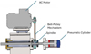 |
Fig. 4 The schematics of the positioning. |
Three phase induction motor data.
Parameter combinations tested in St52 hydraulic tube end forming.
2.2 Numerical analysis
A 3D simulation model was built with Simufact Forming finite element software. The schematic of the simulation model is given in Figure 4. The tapered head tool is designed to move on the inner surface of the tube end with point contact for orbital forming. As shown in Figure 5, the tube end involved in the plastic deformation was included in the FE simulation at a length of 30 mm from the free edge. This numerical analysis assumed isotropic plasticity and used the Von Mises yield criterion. The upstream tube was considered rigid, and the medium friction coefficient was chosen according to Coulomb's friction law. In this way, it was possible to prevent movement and rotation. The steel tube material was checked against the damage equation in the material library of the simulation program. The Forming Limit Diagram (FLD) was used to check for simulation. As a result of the simulation, it was possible to observe whether damage such as cracks or deformation would occur in the material.
The Lagrangian formulation (Eq. (6)) is used to describe the incremental properties of the plastic law when applying incremental deformation to the metal forming process [27]. This formulation governs the evolution of stresses and strain rates under frictional contact and plastic flow, and it is implemented within the finite element solver to ensure equilibrium at each deformation increment. The steel tube material was evaluated using the damage criteria in the simulation software's material library, and the Forming Limit Diagram (FLD) was used to assess failure mechanisms such as cracking or excessive deformation during forming.
 (6)
(6)
Here, material volume V and surface Sf, Lik. is the velocity gradient, ṫi is the surface traction rate, ϑi is the deformed body volume.
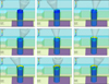 |
Fig. 5 The schematic of the simulation model. |
3 Result and discussion
The selection of an end forming method for tube assembly requires focus on the function of the tube rather than the forming process itself. In this study, the formability of tube ends produced by orbital forming was systematically evaluated through a series of controlled experiments. Comparative analysis of the experimental results was performed to assess the influence of key process parameters, including forming pressure, frequency, and forming time, on formability and overall process performance.
3.1 FE analysis
The finite element (FE) analysis determined that the force required for forming in the Z-axis direction is 0.5 tons, as illustrated in Figure 6, alongside a turret torque of 20 Nm presented in Figure 7. In the simulation with a 500 kg load, high effective plastic strain (EPS) values ranging from 1 to 1.25 were observed locally within the deformation zone. Figure 8 shows that a prob value of 1.34 EPS on the deformed surface indicates significant plastic deformation. Localized areas of high EPS suggest potential weak spots where intense plastic deformation may occur, particularly on the inside of the tube, which could lead to surface failures at the contact points of the tapered die. Moreover, the EPS value measured in the deformation zone on the outer surface of the tube was calculated to be 0.62. Strain values between 0.2 and 0.6 indicate moderate plastic deformation, suggesting that while permanent deformation has taken place, no damage has been detected thus far. It is notable that the EPS value decreases rapidly on the outer surface within the deformation zone, approaching zero at the end of the flared workpiece's surface. This implies that the material can be permanently deformed beyond its elastic limit. Additionally, the analysis indicates that the equivalent stress at the maximum load remains below the ultimate stress, demonstrating that the material has not reached its breaking point. The ultimate stress value represents the maximum stress the material can endure before failure. Therefore, it can be concluded that the orbital forming process, which operates at lower loads, is conducted within a safe range.
The analysis revealed a maximum equivalent stress of 481.25 MPa, as illustrated in Figure 9. This value, being lower than the ultimate stress of 505 MPa, indicates that the deformation did not reach a catastrophic level. At this stage, the material has experienced significant plastic deformation, as evidenced by the EPS results. This suggests that the process can be executed without the immediate risk of failure or cracking. The fact that the stress remains below the ultimate stress threshold confirms that the forming process is within safe limits. Despite the considerable deformation, the material maintains its structural integrity, which is crucial for ensuring that the formed parts are functional and reliable for their intended applications.
In cold forming the steel tube end, the material undergoes plastic deformation, which reorganizes the dislocation structures within the steel's crystalline lattice [28]. These dislocations interact and hinder one another's movement, resulting in increased strength and hardness, albeit at the cost of reduced ductility. The deformation in tube end forming occurs at relatively low temperatures, which is why this process is classified as cold forming, as opposed to hot forming, where deformation occurs at elevated temperatures and may lead to recrystallization. Carrying out forming operations below the recrystallization temperature ensures that the hardening benefits from processing are preserved. To manage temperature and mitigate friction—which can cause localized heating—effective lubrication and cooling are essential during the cold forming procedure. Various probe temperature values within the deformation zone during the forming finite element analysis are indicated in Figure 10, where the average surface temperature in this area is calculated to be 69.59 °C. These temperatures were evaluated for potential simulation damage using the Forming Limit Diagram (FLD) due to work hardening in the St52 hydraulic tube, confirming that no damage occurred.
 |
Fig. 6 Z-Force diagram. |
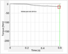 |
Fig. 7 Orbital press torque diagram. |
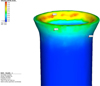 |
Fig. 8 FE model EPS result. |
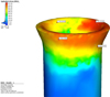 |
Fig. 9 FE model equivalent stress result. |
 |
Fig. 10 FE forming temperature result. |
3.2 Forming defects and quality
The surface quality and integrity of the formed tube ends were evaluated under various parameters to identify the optimal conditions for producing defect-free components in this section. The presence and severity of forming defects—including wrinkles, cracks, material thinning, and issues with roundness—were assessed across different experimental conditions. The integrity and accuracy of the processed surfaces during the tube and tube end flaring process directly influence the assembly and sealing capabilities within hydraulic systems, which in turn affects performance, durability, cost-efficiency, and sustainability. In manufacturing environments, potential defects such as tool wear, lubrication and cooling problems, and vibrations can lead to diminished circular features, measurement precision, and overall surface quality. Based on the experimental findings, it was determined that workpieces with the specified expansion ratio and surface integrity were successfully produced at various pressure and frequency values during the processing of thick-walled tubes utilizing a rotating conical die. The forming limit of the orbital rotary forming process remains within an acceptable range for hydraulic tube end flaring, as corroborated by the experimental data.
The experimental studies demonstrated that all workpieces were successfully flared to the desired diameter without significant surface deformation, as shown in Figure 11. Due to the linear contact provided by the conical die, no buckling was observed in any of the test samples. Figure 11 shows that buckling was effectively prevented, enabling the flaring process to occur within the forming limit without any diameter alterations under all processing conditions.
In the context of hydraulic piping, leak-proof connection elements are designed to allow movement along the tube during assembly. However, increasing the tube diameter during end forming can cause assembly issues, affect the tube's circularity, and result in an uneven load distribution. Ultimately, these issues result in reduced connection performance and unreliable leakage. Experimental studies indicated that applying orbital forming with a conical die does not increase the diameter of the tube at points in proximity to the machining zone, as shown in Figure 12.
The implementation of this methodology effectively avoids any potential problems that might otherwise impede the assembly process.
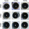 |
Fig. 11 The flaring surface of the St52 hydraulic tube under different machining conditions. |
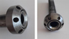 |
Fig. 12 The flared workpieces hydraulic tube end and fitting. |
3.3 Surface roughness
Surface roughness is crucial when assessing the quality of flared components because it significantly affects the integrity of the surface. Achieving an optimal surface finish requires consideration of various process variables. The roughness profile offers insight into the effects of machining conditions [29]. Modelling machining conditions provides a method of analysing and addressing challenges associated with achieving specific surface roughness values, particularly with hard materials [30]. The arithmetic mean of surface roughness (Ra) is a key parameter for assessing surface quality [31]. In this study, Ra was used as a factor in modelling machining conditions for optimizing surface properties.
The findings of this analysis are represented graphically in Figure 13, demonstrating the relationship between the modelled forming conditions and the resulting surface roughness. The research revealed that machining loads and pressure significantly influence surface roughness under both high and low forming conditions, making them the most critical factors in the orbital forming process. The impact of forming parameters became more pronounced, with surface quality deteriorating at both low and high forming conditions. The poorest surface quality was observed in low-pressure machining combined with low frequency, as illustrated in the results. Conversely, the combination of mean pressure and mean frequency led to the most significant reduction in surface roughness. While surface quality deteriorates at high pressure and high frequency, this trend is reversed at low pressure, with worsening effects observed at low frequency parameters. The increase in forming pressure from 3 Bar to 4 Bar led to a remarkable 73% improvement in surface quality. Acceptable surface roughness values for tube end flaring can vary based on specific applications, industry standards, and the materials being used. These values are not fixed and can differ according to the unique requirements of each application. For instance, aerospace or medical applications often demand tighter tolerances and smoother surfaces [32]. In many industrial contexts, roughness values typically range from 0.4μm to 12.5μm [33]. These roughness values are categorized as falling between grades N4 and N10 [34]. This range generally strikes a balance between production efficiency and surface finish, particularly in applications where extreme precision or minimal friction is not essential. Consequently, this indicates that the quality of the finish is acceptable for many industrial applications. In tube end flaring tests, a surface roughness value falling within the range N4 (0.855 μm) to N7 (3.065 μm) suggests that the finish quality is satisfactory for many industrial uses. Figure 13 illustrates that mean forming conditions provide substantial benefits regarding surface roughness compared to both low and high extreme conditions.
 |
Fig. 13 Surface Roughness variation under different forming conditions. |
3.4 Microscopic surface Integrity
When the SEM results are analysed collectively, it becomes apparent that the interaction between the conical die and the workpiece takes place under a steady propagation regime marked by consistent plastic flow tracks oriented along the material slip direction. These surface features suggest a controlled friction behavior and a slip-dominant deformation mechanism, rather than localized adhesion or adhesive wear. Importantly, no macroscopic surface cracking, layer separation or signs of severe wear were observed. This confirms that contact stresses remain below the critical threshold for initiating surface damage, as indicated in FEM result Figure 9. As can be seen from Figure 14, the severity of plastic deformation increases from low to high. The material's plastic flow is not yet fully stable at low force and frequency levels, and the texture of the raw material is still visible on the surface in some places. However, a significant improvement in surface integrity was observed when the optimum machining conditions were reached. The regular, continuous plastic flow traces in Figure 14 demonstrate the formation of a stable tribological regime at the tool–workpiece interface. The “polished” appearance of the surface shows that the material replicates the die geometry with high precision, minimising friction-induced energy losses. This finding is consistent with the low power consumption data recorded in experimental studies at optimum values. The surface characteristics change as the severity of plastic deformation increases at the highest force and frequency combination. The micro-grooving’s and isolated micro-voids identified in Figure 14 demonstrate the most significant impact of incremental deformation on the material's surface. However, the shallow structure of these micro-defects and their lack of tendency to propagate as cracks into the material confirm that the process remains within safe limits even at the highest loads.
This is due to equivalent stress values from numerical analyses remaining below the material's ultimate tensile strength (UTS), as excessive stress concentrations are dynamically redistributed on the surface due to orbital motion. These microscopic observations are closely correlated with numerical findings showing that equivalent stress levels remain below the ultimate tensile strength, thus ensuring forming safety. From a wear perspective, the absence of significant surface distortion indicates reduced friction-induced energy loss, which directly contributes to the lower power consumption observed under optimum conditions. The lack of noticeable surface deformation further demonstrates that friction-induced energy loss is minimized given in Figure 15. SEM images confirm that the conical die trajectory expansion process delivers high geometric accuracy and process robustness through stable surface evolution and controlled contact mechanics.
 |
Fig. 14 SEM images of orbital flared tube ends. |
 |
Fig. 15 SEM images of the forming sample at 2560 N and 320 rpm. |
3.5 Power consumption
Achieving zero leakage in high-pressure hydraulic systems is primarily reliant on the use of precision mechanical fittings specifically designed to facilitate reassembly. These fittings allow for free movement along the tube, while the machining performed on the tube end ensures an impermeable connection. The flaring process, essential for creating this secure connection, can be executed through various methods such as the traditional split die and cone technique, impact forming, hydraulic press forming, and pneumatic forming. However, these methods often require significant loads and motor power, resulting in increased energy consumption and longer processing times. In this study, the linear contact spinning method is proposed as an innovative technique for the tube end flaring process. St52 hydraulic steel tube ends can be flared using the servo drive orbital forming process, which operates with lower vibration and load values. While it is feasible to process hydraulic steel tube ends in a horizontal position via the internal forming method, this approach yields more symmetrical and smoother circular end shapes. Consequently, the surface roughness values and diameter tolerances at the tube end become critical factors. The energy efficiency of the tube end forming process, along with its optimization, can lead to a significant reduction in energy consumption. The experimental study illustrates the power consumed during this process, revealing a consistent decline in power consumption as machining conditions and processing time improve, as depicted in Figure 16. Notably, at a machining time of 17 seconds, power consumption decreases by approximately 80% when high machining parameter values are applied, which underscores the potential for substantial energy savings through process optimization. Specifically, the combined effect of forming pressure, rotational frequency, and forming time shifts the deformation mode from global axial loading to localised incremental plastic deformation. It is evident that, due to the point-contact kinematics of the orbital tool, the instantaneous contact area remains limited. This, in turn, has a significant effect on the required forming force per cycle, and consequently the total energy demand. This mechanism elucidates the observed reduction in power consumption of up to 80%. Furthermore, the cyclic and rotational nature of the loading promotes a more uniform circumferential strain distribution, effectively suppressing localised strain concentration, ovalisation, and elastic instability. Consequently, the phenomenon of elastic spring-back and the presence of residual stress gradients are mitigated, thereby enhancing the circularity of the material by approximately 80%. The findings indicate that the recorded performance enhancements are not merely a consequence of empirical evidence but are instead directly associated with the stabilisation of material flow and the enhancement of safety in the forming process, which is attributable to the incremental deformation mechanics of the orbital forming process. The orbital forming-based tube forming technology discussed above demonstrates strong alignment with lean manufacturing and clean production principles. The technology's incremental orbital forming kinematics enables a high degree of geometric adaptability while maintaining controlled material flow, reducing excess deformation and material waste. By integrating tube flaring and end forming into a single stage, the process eliminates intermediate machining and reduces tooling requirements. The simplified tool–workpiece interaction, with localised contact and reduced forming forces, contributes to lower energy consumption and enhances process efficiency, leading to a measurable decrease in process-related environmental impact. From a manufacturing sustainability perspective, this forming strategy provides a viable pathway toward resource-efficient tube forming, satisfying clean production objectives through improved safety, minimised waste generation, and reduced operational energy input.
 |
Fig. 16 The variation of power consumption with forming conditions. |
3.6 Dimensional accuracy
The dimensional accuracy of formed tube ends was assessed in terms of diameter, length, and geometric tolerances. This section compares the deviations from target dimensions across various experimental settings to identify the factors influencing dimensional accuracy. In manufacturing context, a range of essential geometric characteristics are typically evaluated, including straightness, flatness, cylindricity, and roundness. Among these, roundness (R) holds particular importance for the geometric precision of cylindrical components. Deviations from the ideal roundness are often due to errors introduced during the machining process, reflecting discrepancies in macro-geometry rather than microgeometry [35].
Achieving an optimal degree of roundness is a critical and challenging endeavor, particularly given that the components have already undergone multiple stages of machining and forming. It is vital to ensure precise roundness at this advanced stage of production to meet the stringent quality standards and functional requirements typical in manufacturing. The term ‘eccentricity’ refers to the positioning of the center of the assessed profile relative to the data point. This is a vector quantity that encompasses both magnitude and direction. The magnitude of eccentricity is defined as the distance from the center of the relevant reference circle, represented as the distance from the data point. The direction is indicated as an angle from the data point. In this context, the eccentricity is illustrated in Figure 18, with the left column depicting eccentricity and the right column showing the deviation rate. Certain similar results are omitted from this graph for clarity. This optimization study concentrates on the specific processing conditions that yield the lowest values for surface roughness and deviation across all three frequency levels. It has been shown that deviations increase and eccentricity deteriorates when processing parameters are set at either low or high extremes. This implies that a careful balance in processing conditions is essential for minimizing surface roughness while preserving the desired geometric integrity. An examination of Figure 18 reveals that, under low machining parameters, the profile's eccentricity measured 5.04 μm, with a corresponding deviation value of 178.19823 μm. These results indicate a decline in surface quality, likely due to elevated deviation values and misalignment between the axes and the reference circle. Under experimental conditions 1, the roundness deviation registered as significantly high, at 178.19 μm. Low forming pressure, moderate frequency, and relatively long process time probably did not provide sufficient material flow and uniform expansion. Insufficient pressure caused irregular forming or deviation, especially at the tube end. Low energy input (1536 N at 10 Hz) may be insufficient for complete tube forming. Even long forming time (90 s) did not allow sufficient material relaxation and distribution. Low spindle speed (200 rpm) increased symmetry problems. The tube end exhibits controlled roundness but requires local corrections. The process is stable under 3 bar/1536 N but may require optimization. Low forming pressure, moderate frequency, and a relatively extended process time likely did not provide adequate material flow and uniform expansion. Insufficient pressure led to irregular forming and deviations, particularly at the tube end. The low energy input (1536 N at 10 Hz) may not have been sufficient for complete tube formation. Even a prolonged forming time of 90 seconds did not allow for adequate material relaxation and distribution. Additionally, the low spindle speed of 200 rpm exacerbated symmetry issues. While the tube end displayed controlled roundness, it necessitated localized corrections. The process remained stable at 3 bar/1536 N, although optimization might be required. The prolonged machining time under low-pressure conditions, combined with the effects of roundness and the loss of parallelism between the workpiece and the spindle during the forming process, resulted in a significant decline in circularity and a corresponding reduction in surface quality. However, this adverse impact was notably mitigated as the machining parameters were enhanced. In the orbital forming process conducted at 4 bar pressure, deviation values were recorded as 51.01542 μm, 40.77924 μm, and 49.75553 μm for all three frequencies (10 Hz, 13 Hz, 16 Hz), respectively. The optimal processing results were achieved at a frequency of 13 Hz under the 4 bar processing conditions. A comprehensive evaluation of Figures 11–18 demonstrates that the best outcomes were aligned with the average values established in this study, particularly regarding surface roughness, power consumption, and dimensional precision in the orbital forming tube end flaring process with a conical die. Under high-pressure processing conditions, the increased load applied to the workpiece leads to a greater angular deviation from the reference axis, resulting in a decline in both circularity and surface roughness. However, the significantly reduced processing time in these conditions contributes to lower deviation values compared to those seen under low-pressure processing. This indicates that, although high-pressure conditions may pose challenges in maintaining geometric accuracy, they also provide the advantage of minimizing deviations through more efficient processing, as illustrated in Figure 17.
 |
Fig. 17 Variation of deviation under different forming conditions. |
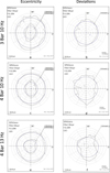 |
Fig. 18 Tube end flaring eccentricity and deviations under different forming condition. |
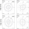 |
Fig. 18 (Continued). |
3.7 Process parameters
The application of high-pressure hydraulic and pneumatic systems necessitates the utilisation of fittings that can ensure absolute leakage-free performance. However, machining a tube end flare that guarantees zero leakage is a significant challenge. The orbital tube end flaring system may be regarded as an enhanced iteration of the conventional split die and cone approach, featuring a rolling conical die and an idle rotating die configuration, which enables precise control over the expansion process. This system expands the tube end by rolling the material between the die, which grips the tube from the outside using teeth-oriented perpendicular to the axial rotation direction, and an eccentrically rotating inner cone. When the jaw is closed, the teeth of the die create a clamping diameter that is 0.03 mm smaller than the diameter of the tube, thereby effectively preventing the tube from rotating or slipping during the process.
The orbital flaring method represents a significant innovation in comparison to traditional methods, as it replaces the split die as the expansion mechanism with a rolling die. The idle rotating outer die and the rolling end of the eccentrically conical die, which have been specially designed for this process, are offset between the outer die and the rolling eccentric die to create a focal point at which the desired tube shape can be formed. The orbital system is comprised of three principal components: the clamping jaw, the conical die, and the idle rotating outer die. The tube is secured within the outer die in such a way that the expansion die maintains its concentric alignment with the rotation centreline of the main shaft. The tube holder is designed with the objective of maintaining concentricity with a tolerance of 0.03 mm to accommodate any potential variations in the dimensions of the tube being processed. The centreline of the cone is configured to rotate around the centreline of the main drive shaft during the operational phase. Since the offset centred turret ball establishes linear contact with the tube throughout the expansion process, the rolling load is minimised. The motor torque and pneumatic cylinder power were calculated to meet the requisite load requirements and subsequently verified by analysis to ensure efficient operation. It was established that when a load of 3000N was applied, linear contact led to a notable reduction in the load necessary for the expansion process in comparison to field theme.
In the context of optimising the design of eccentric rotating conical dies for orbital forming, an investigation was carried out to ascertain the efficacy of various types of hardened steel in machining the ends of St52 hydraulic tubes. The use of a conical die manufactured from AISI 1040 steel exhibiting a hardness of 50 HRC was found to result in the rapid wear of the die tip, which in turn had an adverse impact upon the surface quality of the workpiece. The results were enhanced by undertaking additional trials utilising a steel designated as 1.2379 (DIN X153CrMoV12) at two distinct hardness degrees, namely 45 HRC and 60 HRC. Similarly, the die with 45 HRC exhibited accelerated wear, resulting in a reduction in surface quality and a lack of precision in dimensions. However, when the same steel with a hardness of 60 HRC was employed, the optimal results were obtained. Consequently, the utilisation of 60 HRC DIN X153CrMoV12 steel is advised for the optimisation of the orbital forming process, based on the observed performance and trends. In conclusion, comparing the experimental results from a series of studies on tube end formability using the orbital forming method enables researchers to understand the underlying factors influencing the process and make informed decisions regarding process optimization and parameter selection. Such comparative analyses contribute to advancing the understanding and implementation of orbital forming in industrial applications.
For the conical die, the value of the orbital flaring ratio decreases slightly depending on the value of the half apex angle [36], in this study the value of λc is 0.357 at 37°. The equivalent diameter of conical tools, α, is an effective parameter to limit the flaring ratio. Furthermore, it has been demonstrated that when the equivalent diameter of the conical tool is less than the half apex angle, the limiting expansion ratio increases. In view of the above evidence, it was determined that the equivalent diameter of the conical tool in question was 15°, which is less than the half apex angle.
The variability in the results produced between repeated experiments is compared to evaluate the process robustness. The average orbital forming conditions (4 Bar-13Hz) are found to give optimum results in terms of surface roughness and dimensional precision. When the forming process is carried out at lower load and pressure levels, a notable decline in surface quality and circularity is evident, attributable to the extended processing times and the radial and axial loads exerted on the workpiece during rolling. The orbital forming flaring method represents a significant innovation in tube and tube joint technology. It will be possible to achieve guaranteed production of zero-leakage joints at lower power and time conditions by replacing the traditional split die as the expansion mechanism with the orbital forming method. Another unique aspect of this study is the way in which the rotating turret advances during the forming process. The specially shaped rotating turret, which will be forming the metal, allows the turret to advance inside the tube without crushing or bursting it, and can apply enough force to give the tube the desired shape. To achieve this feed, the pneumatic cylinder system was chosen over the more expensive hydraulic system, reducing costs. Consequently, comparing the experimental results of a series of studies on tube end formability using the orbital forming method will help researchers understand the key factors affecting the process and make informed decisions on process optimization and parameter selection. Such comparative analyses are expected to contribute to advancing the understanding and application of orbital forming in industrial applications.
4 Conclusion
This study focuses on forming thick-walled St52 hydraulic tube ends using the conical die forming method with different process parameters. The stability, repeatability and potential for optimisation of the process are evaluated in detail. The limited variability in the results obtained from repeated experiments indicates that the process is highly stable and repeatable. Consistency between the tube end expansion process performed using an 80 mm diameter, 3000 N capacity pneumatic cylinder and the numerical analysis results confirm the accuracy and reliability of the experimental system. Successful performance of the forming process at reduced load and pressure levels in accordance with the experimental design demonstrates the method's advantages in terms of energy efficiency and process control.
One of the most significant outcomes of the conical die orbital forming method is the absence of an undesirable increase in tube diameter in areas close to the forming zone. This enables the fittings on the tube to be moved more precisely and ensures a more balanced load distribution in the connection area. Therefore, this method offers significant advantages, particularly for tube connection applications that require leak-proofness and precise assembly.
Surface roughness results show that the maximum roughness value recorded under low forming parameters is 3.065 μm, while the optimum surface quality is obtained at 0.855 μm at 4 bar pressure and 13 Hz frequency. The fact that the average surface roughness values obtained across all experimental conditions fall within the limits for leakage-proof performance indicates the suitability of the method concerning functional surface quality. Additionally, it has been established that approximately a 65% improvement in surface roughness can be attained through the optimal design of the conical die orbital forming process.
Finite element analysis has shown that keeping equivalent stress values below the material's ultimate strength is crucial for ensuring consistent production quality and minimizing defects. The material's capacity to undergo plastic deformation without cracking or notable surface imperfections, even at relatively low stress levels, highlights the successful optimization of fundamental process parameters. The seamless completion of all experimental trials and the attainment of the desired geometric properties further reinforce the industrial applicability of this method.
The absence of buckling, local compression, or uncontrolled expansion in other regions of the tube during the forming process indicates that orbital forming involves localized and controlled deformation. However, under high-pressure conditions, increased radial and axial loads caused the workpiece to deviate from the reference axis, resulting in a slight reduction in circularity and surface quality. Despite this, shorter processing times achieved at high pressures led to lower overall geometric errors compared to those observed under low-pressure conditions. This demonstrates that while high-pressure scenarios present risks to geometric accuracy, overall deformation can be effectively managed due to reduced processing times.
SEM analysis confirms that the applied force and frequency have a significant impact on the surface morphology of the orbital flanging process. Smooth and uniform plastic flow traces obtained under optimum machining conditions indicate a stable tribological regime at the tool-workpiece interface, proving high-efficiency processing. Although the highest machining parameters result in shallow micro-grooves and isolated micro-voids, representing the most intense effects of incremental deformation on the surface, the absence of any macroscopic cracks or signs of delamination shows that forming reliability is maintained even under the most demanding conditions. The numerical analysis results are supported by these microscopic findings, which show that the equivalent stress values remain within the tensile strength limits of the material. This reinforces the full compliance of the proposed method with industrial precision targets.
In terms of die material, no permanent deformation was noted in conical molds made of DIN X153CrMoV12 steel, exhibiting a hardness of 60 HRC, which yielded the most stable results. This situation has been an important indicator for the use of high-hardness and wear-resistant mold materials for long-term stability in orbital forming processes. Finally, under low-pressure conditions, increasing radial and axial loads, the distance between the workpiece profile center and the spindle, along with extended processing times, contributed to a significant deterioration in circularity and, consequently, a decline in surface quality. However, it was observed that this negative impact diminished considerably as processing parameters were enhanced. Notably, the minimum deviation values were recorded at all frequency levels during orbital forming processes conducted at 4 bar pressure, leading to an improvement of approximately 80% in circularity. These findings clearly indicate that the right combination of pressure and frequency is essential for achieving optimal geometric accuracy and surface quality.
Funding
This research received no external funding.
Conflicts of Interest
Both authors declare that there’s no conflict of interest.
Data availability statement
Data is provided within the manuscript
Author contribution statement
Havva Demirpolat, Conceptualization, methodology, formal analysis, supervision, writing—original draft preparation, writing—review and editing, software; Seracettin Akdı, validation, resources, data curation, analysed the data.
References
- A.R. Khalil Hazawi, R.K. Abdel-Magied, M.N. Elsheikh, An experimental analysis of a flaring process for tube ends using a novel spinning tool, Int. J. Adv. Manufactur. Technol. 92, 157–165 (2017) [Google Scholar]
- C. Bell, J. Corney, N. Zuelli, D. Savings, A state of the art review of hydroforming technology: Its applications, research areas, history, and future in manufacturing, Int. J. Mater. Form. 13, 789–828 (2020) [Google Scholar]
- K. Martinsen, S.J. Hu, B.E. Carlson, Joining of dissimilar materials, CIRP Annals 64, 679–699 (2015) [Google Scholar]
- D.Y. Yang, M. Bambach, J. Cao, J.R. Duflou, P. Groche, T. Kuboki, A. Sterzing, A.E. Tekkaya, C. W. Lee, Flexibility in metal forming, CIRP Ann. 67, 743–765 (2018) [CrossRef] [Google Scholar]
- M. Merklein, J.M. Allwood, B.A. Behrens, A. Brosius, H. Hagenah, K. Kuzman, K. Mori, A.E. Tekkaya, A. Weckenmann, Bulk forming of sheet metal, CIRP Ann. 61, 725–745 (2012) [Google Scholar]
- P. Rosa, J. Rodrigues, P. Martins, External inversion of thin-walled tubes using a die: experimental and theoretical investigation, Int. J. Machine Tools Manufact. 43, 787–796 (2003) [Google Scholar]
- L. Venugopal, M. Davidson, Analysis of tube end forming process using Taguchi design of experiments, Usak Univ. J. Mater. Sci. 1, 137–145 (2012) [Google Scholar]
- L. Venugopal, S. Kosaraju, Investigation on tube end forming behaviour of AA6061 alloy, Adv. Mater. Process. Technolog. 8, 1217–1226 (2022) [Google Scholar]
- G.G. Miller, Tube forming processes: a comprehensive guide, Soc. Manufactur. Eng. (2003) [Google Scholar]
- B. Almeida, M.L. Alves, P.A.R. Rosa, A.G. Brito, P.A.F. Martins, Expansion and reduction of thin-walled tubes using a die: experimental and theoretical investigation, Int. J. Machine Tools Manufact. 46, 1643–1652 (2006) [Google Scholar]
- P.A. Rosa, J.M. Rodrigues, P.A. Martins, Internal inversion of thin-walled tubes using a die: experimental and theoretical investigation, Int. J. Machine Tools Manufact. 44, 775–784 (2004) [Google Scholar]
- T. Wen, C. Yang, S. Zhang, L. Liu, Characterization of deformation behavior of thin-walled tubes during incremental forming: a study with selected examples, Int. J. Adv. Manufactur. Technol. 78, 1769–1780 (2015) [Google Scholar]
- K. Manabe, H. Nishimura, Forming loads in tube-flaring with conical punch-study on nosing and flaring of tubes V, J. Jpn. Soc. Technol. Plast. 24, 47–52 (1983) [Google Scholar]
- K. Kitazawa, Improvement in flaring limit of thin-walled circular tubes using precurling method, JSME Part C 62, 773–778 (1996) [Google Scholar]
- Y.H. Lu, Study of tube flaring ratio and strain rate in the tube flaring process, Finite Elements Anal. Des. 40, 305–318 (2004) [Google Scholar]
- J.P. Pragana, I.M. Bragança, C.M. Silva, P.A. Martins, Integration of tube end forming in wire arc additive manufacturing: an experimental and numerical investigation, Int. J. Adv. Manufactur. Technol. 117, 2715–2726 (2021) [Google Scholar]
- S. Baek, X.G. Song, Y.C. Park, T.G. Kim, K.Y. Park, K.S Kim, Study on the flange manufacturing of tube with high pressures, ASME Int. Mech. Eng. Congr. Exposit., American Society of Mechanical Engineers (2012) [Google Scholar]
- P. Lin, Y. Guan, P. Kong, S. Jiang, D. Sun, S. Guo, B. Yan, H. Feng, L. Yang, Y. Zhang, Transfer mechanisms of folding defect for thin-walled tube end flanges formed by flaring-upsetting hybrid process, J. Manufactur. Process. 125, 321–336 (2024) [Google Scholar]
- S. Kajikawa, K. Uchida, T. Kuboki, Rotary tube flaring using a conical punch with grooves for high forming limit and productivity, CIRP Ann. 74, 387–391 (2025) [Google Scholar]
- S. Zhang, T. Kuboki, M. Akiyama, S. Kajikawa, Influence of mechanical properties of tube on forming limits and deformation characteristics in an expansion drawing process, J. Manufactur. Sci. Eng. 146, 071005 (2024) [Google Scholar]
- V. Cristino, J.P. Magrinho, G. Centeno, M.B. Silva, P.A.F. Martins, Theory of single point incremental forming of tubes, J. Mater. Process. Technol. 287, 116659 (2021) [Google Scholar]
- T. Altan, S.-I. Oh, H.L. Gegel, Metal forming: fundamentals and applications (1983) [Google Scholar]
- P.D.T. Caiza, S. Sire, T. Ummenhofer, Y. Uematsu, Full and partial compression fatigue tests on welded specimens of steel St 52-3. Effects of the stress ratio on the probabilistic fatigue life estimation, Appl. Eng. Sci. 10, 100091 (2022) [Google Scholar]
- Y.-H. Lu, A study of the finite element stabilized matrix to the hemispherical cup-drawing process, Comput. Struct. 60, 235–242 (1996) [Google Scholar]
- F. Elerian, W.M. Helal, M. Aboueleaz, Methods of roundness measurement: An experimental comparative study, J. Mech. Eng. Res. Dev. 44, 173–183 (2021) [Google Scholar]
- O. Zakharov, I. Bobrovskij, A. Kochetkov, Analysis of methods for estimation of machine workpiece roundness, Proc. Eng. 150, 963–968 (2016) [Google Scholar]
- A. Makinouchi, H. Ogawa, Y. Tozawa, Simulation of sheet bending processes by elastic-plastic finite element method, CIRP Ann. 38, 279–282 (1989) [Google Scholar]
- X. Wu, Deformation and evolution of life in crystalline materials (2019) [Google Scholar]
- P. Benardos, G.-C. Vosniakos, Predicting surface roughness in machining: a review, Int. J. Mach. Tools Manufact. 43, 833–844 (2003) [Google Scholar]
- F.J. Pontes, J.R. Ferreira, M.B Silva, A.P Paiva, P.P Balestrassi, Artificial neural networks for machining processes surface roughness modeling, Int. J. Adv. Manufactur. Technol. 49, 879–902 (2010) [Google Scholar]
- J. Dobes, J.E.S. Leal, J. Profeta, M.M. Sousa, F.P.L. Neto, A.P. Filho, R.V. Arencibia, Effect of mechanical vibration on Ra, Rq, Rz, and Rt roughness parameters, Int. J. Adv. Manufactur. Technol. 92, 393–406 (2017) [Google Scholar]
- S. Bose, S.F. Robertson, A. Bandyopadhyay, Surface modification of biomaterials and biomedical devices using additive manufacturing, Acta Biomater. 66, 6–22 (2018) [Google Scholar]
- M. Wieland, P. Hänggi, W. Hotz, M. Textor, B.A. Keller, N.D Spencer, Wavelength-dependent measurement and evaluation of surface topographies: application of a new concept of window roughness and surface transfer function, Wear 237, 231–252 (2000) [Google Scholar]
- S. Siraj, H. Dharmadhikari, N. Gore, Modeling of roughness value from tribological parameters in hard turning of AISI 52100 steel, Proc. Manufactur. 20, 344–349 (2018) [Google Scholar]
- E. Gadelmawla, Simple and efficient algorithms for roundness evaluation from the coordinate measurement data, Measurement 43, 223–235 (2010) [Google Scholar]
Cite this article as: H. Demirpolat, S. Akdi, Hydraulic St52 tube end orbital forming: improving forming limits and surface quality and dimensional precision through finite element analysis and experimental validation, Mechanics & Industry 27, 21 (2026), https://doi.org/10.1051/meca/2026017
All Tables
All Figures
|
Fig. 1 Hydraulic St52 steel tube section view. |
| In the text | |
|
Fig. 2 Experimental setup. |
| In the text | |
|
Fig. 3 Conical die contact geometry for flaring load assessments. |
| In the text | |
|
Fig. 4 The schematics of the positioning. |
| In the text | |
|
Fig. 5 The schematic of the simulation model. |
| In the text | |
|
Fig. 6 Z-Force diagram. |
| In the text | |
|
Fig. 7 Orbital press torque diagram. |
| In the text | |
|
Fig. 8 FE model EPS result. |
| In the text | |
|
Fig. 9 FE model equivalent stress result. |
| In the text | |
|
Fig. 10 FE forming temperature result. |
| In the text | |
|
Fig. 11 The flaring surface of the St52 hydraulic tube under different machining conditions. |
| In the text | |
|
Fig. 12 The flared workpieces hydraulic tube end and fitting. |
| In the text | |
|
Fig. 13 Surface Roughness variation under different forming conditions. |
| In the text | |
|
Fig. 14 SEM images of orbital flared tube ends. |
| In the text | |
|
Fig. 15 SEM images of the forming sample at 2560 N and 320 rpm. |
| In the text | |
|
Fig. 16 The variation of power consumption with forming conditions. |
| In the text | |
|
Fig. 17 Variation of deviation under different forming conditions. |
| In the text | |
|
Fig. 18 Tube end flaring eccentricity and deviations under different forming condition. |
| In the text | |
|
Fig. 18 (Continued). |
| In the text | |
Current usage metrics show cumulative count of Article Views (full-text article views including HTML views, PDF and ePub downloads, according to the available data) and Abstracts Views on Vision4Press platform.
Data correspond to usage on the plateform after 2015. The current usage metrics is available 48-96 hours after online publication and is updated daily on week days.
Initial download of the metrics may take a while.