


| Issue |
Mechanics & Industry
Volume 27, 2026
|
|
|---|---|---|
| Article Number | 27 | |
| Number of page(s) | 12 | |
| DOI | https://doi.org/10.1051/meca/2026026 | |
| Published online | 12 June 2026 | |
Original Article
Development of a single porous material 3D-printed plantar orthosis to improve recycling and preserve the health of podiatrists
1
Aix-Marseille Univ, CNRS, ISM, Marseille, France
2
Aix-Marseille Univ, Faculté des Sciences Médicales et Paramédicales, École des Sciences de la Réadaptation, École de Podologie-Pédicurie, Marseille, France
3
Aix-Marseille Univ, Univ Gustave Eiffel, LBA, Marseille, France
* e-mail: This email address is being protected from spambots. You need JavaScript enabled to view it.
Received:
13
October
2025
Accepted:
12
May
2026
Abstract
The aim of this study was to develop a 3D-printed plantar orthosis composed of a single, recyclable material without a covering layer. This study had two objectives: the protection of the podiatrist's health during the creation of the orthosis and the reduction of the orthosis's environmental impact. Indeed, currently podiatrist realize thermoformed orthotics using many manual and arduous operations, as well as the handling of numerous glues and toxic substances. In this paper, the developed orthosis mimics the geometrical and mechanical properties of a thermoformed orthosis including specific pores in the orthosis. Firstly, the materials composing the thermoformed orthosis were characterized from a mechanical point of view. Secondly, specific isotropic pores were applied to a solid TPU block. The size of these pores was calculated using finite element analysis to reproduce the behavior of each material of the thermoformed orthosis. Thereafter, a 3D-printed orthosis was produced and an initial trial with one patient yielded promising outcomes; however, further research involving a larger group of patients is required to confirm these findings. Finally, a fatigue test was conducted on a representative sample, showing that the defined solution appears to withstand one year of use. In the future, the goal is to no longer use thermoformed orthosis but to directly design the orthoses using computer-aided design software. This research opens new possibilities for designing personalized plantar orthosis, enabling the adjustments of local mechanical characteristics to address specific pathological requirements.
Key words: Plantar fasciitis / plantar orthosis / 3D-printing / recycling / cellular materials
© J. Chaves-Jacob et al., Published by EDP Sciences, 2026
 This is an Open Access article distributed under the terms of the Creative Commons Attribution License (https://creativecommons.org/licenses/by/4.0), which permits unrestricted use, distribution, and reproduction in any medium, provided the original work is properly cited.
1 Introduction
Plantar fasciitis is a common foot orthopaedic disorder in adults. It is characterized by damages located on the plantar fascia or by an overload exerted by unadapted locomotion and/or overweight [1,2]. Such pathology induces chronic pain that could be a cause of disability and stiffness of heel or mid-foot area [1,2]. Some authors have demonstrated that inflammatory reaction could be related with plantar fasciitis [3,4]. From a biomechanical perspective, plantar fasciitis can be understood as the consequence of a combination of two factors: excessive force originating from overweight, obesity, or repetitive activity such as long distance running or handling, applied to the plantar arch and overstretching of plantar fascia perturbating the role of impacts absorber of the latter [5–7].
In the majority of cases, the symptoms associated with these disorders can be treated effectively with a plantar orthosis [8]. Indeed, the most recent systematic review has demonstrated their effectiveness [9]. They provide better support for the medial longitudinal arch when walking [10,11]. They also reduce the stress originating from impacts by changing charges distribution to relieve pain from the fascia. Furthermore, orthoses can decrease the torsion between rearfoot and forefoot [12]. These authors have demonstrated that orthosis made to change biomechanical or postural situation in patients suffering from plantar fasciitis, significantly decrease and even suppress pain after 6 weeks of orthosis use.
Technically, the design of the orthosis is able to relieve plantar fasciitis from locomotion load by supporting the longitudinal arch and relieving soft tissue stretch. The metatarsal pads redistribute the force on the metatarsal shafts, thereby relieving pain. Finally, the heel pad keeps the heel in a more neutral position [13].
Thus, plantar orthotics are designed from a base that is either cut or thermoformed, the latter option being more patient-specific. Subsequently, the various correction, stabilization, and comfort elements are bonded to the base, contingent upon the patient's anatomy and pathology. The base is composed of polycaprolactone (PCL) with knitted polyester fibers, which are used for their thermoformable characteristics. Upon cooling, the material exhibits a shore A hardness of approximately 90–95, facilitating the bonding of the other elements within the sole with stability and ease. The majority of these elements are manufactured from ethylene vinyl acetate (EVA), a material selected for its favorable shock absorption properties, flexibility, and elasticity. The Shore A hardness of EVA can be easily modified in accordance with the specific element and its designated function [14]. Elements and base are generally glued together using an isoprene-based adhesive. It should be noted that isoprene has been categorized as a potential carcinogen (Group 2B) since 1994 [15], and has remained so ever since which can pose health problems for podiatrist using them. It is worthy to also notice that EVA is considered to be a potent carcinogen and a substance that could lead to olfactory injuries [16,17]. In addition to the utilization of toxic products, the fabrication of orthosis necessitates the performance of a multitude of repetitive movements (cutting, gluing and sanding) which are risk factors for the development of musculoskeletal disorders (MSD) among podiatrist [18]. Eventually, making foot orthosis has a health impact on the podiatrist.
Moreover, making foot orthoses also has an environmental impact. Conventional manufacturing processes for orthoses generate a significant amount of material waste due to cutting, sanding, and trial-and-error adjustments. Furthermore, orthosis generally requires replacement approximately every year, increasing material consumption over time [19,20]. Their end-of-life management is also problematic, as recycling is rarely considered. Since conventional orthoses are composed of several materials bonded together, separation of components is difficult, if not impossible, which severely limits recycling options. Beyond recyclability, ecological considerations also include energy consumption, production workflow efficiency, and logistics. Conventional fabrication relies on multiple manual steps and often requires physical storage of plaster casts or foam impressions, as well as repeated patient visits for adjustments. These factors contribute to increased resource use and environmental footprint. Therefore, the environmental impact of foot orthoses should be understood as the cumulative result of material selection, manufacturing processes, product lifespan, and end-of-life management.
In this context, additive manufacturing as an alternative method offers potential advantages by addressing several ecological dimensions, including material efficiency and waste reduction, while simultaneously reducing occupational health risks associated with repetitive manual tasks and exposure to potentially hazardous substances. This technology makes it relatively easy to produce patient-specific foot orthotics [21]. Several 3D printing technologies exist, all with their own advantages and disadvantages, such as fused filament deposition (FDM), selective laser melting (SLM) and PolyJet. FDM printing is often use because of the low cost of the equipment [22]. It has been demonstrated that the utilization of three-dimensional printing technology for the fabrication of orthosis can markedly reduce the time required for their production, from a typical duration of approximately one week to a mere 1.5 h [23]. Consequently, the integration of three-dimensional printing in the manufacturing process would serve to significantly diminish the risk of repetitive strain injury (RSI) among podiatrists, by eliminating the necessity for repetitive manufacturing gestures.
In recent years, several studies have specifically investigated the use of FDM for the fabrication of plantar orthoses and compared it with conventional thermoforming techniques. Unlike thermoformed orthoses, which rely on multi-material assemblies and manual post-processing steps, FDM enables the fabrication of orthoses directly from a digital model using a layer-by-layer deposition of a single thermoplastic material [24,25]. This approach allows greater control over internal geometry, such as infill density and pattern, which can be exploited to locally tune stiffness and mechanical behavior without the need for additional components or bonded elements [26].
From a manufacturing perspective, several authors have reported that FDM-based workflows reduce fabrication time, operator dependency, and inter-practitioner variability when compared to traditional thermoforming methods [25]. Mechanical evaluations have shown that FDM-printed plantar orthoses can achieve stiffness and load-bearing characteristics comparable to conventional orthoses when appropriate design parameters are selected [27]. However, thermoformed orthoses still benefit from long-standing clinical experience and well-established material behavior, whereas FDM-produced orthoses require careful optimization of printing parameters to ensure reproducibility and durability [24].
Overall, the existing literature suggests that FDM represents a promising alternative to thermoforming for the production of patient-specific plantar orthoses, offering enhanced design flexibility and simplified manufacturing workflows, while aiming to reproduce the biomechanical functions of conventional devices rather than surpass them clinically. Further investigations are therefore required to determine how design strategies such as variable porosity can be used to match the functional characteristics of thermoformed orthoses.
In the case of flatfoot pathology, a systematic review from 2023 indicates that 3D-printed orthosis has a number of beneficial effects [28]. Firstly, significant improvements in terms of pain and function were observed in the group wearing customized 3D orthosis compared to a control group not wearing them [29]. For running, the group wearing 3D orthosis reported greater perceived comfort than the control group [30]. However, when comparing the 3D orthosis with a conventional orthosis, the results are more complex. Currently, there is not sufficient data to conclude that 3D orthotics are more effective than thermoformed orthosis in terms of functionality.
So, considering 3D printing is one way of achieving this by using a single thermoformable material that can be recycled and reused. 3D printing also makes it possible to avoid most of the factors that can impact podiatrists's health when manufacturing orthosis, by avoiding repetitive gestures and the use of toxic products. We hypothesize that it is possible to reproduce the characteristics of conventional foot orthotics on 3D printed orthotics by implementing a porosity that varies according to the desired stiffness. Consequently, this study aimed to explore the possibility to design 3D printing foot orthosis with the same healing effects than the conventional ones.
2 Material and methods
2.1 Realization of a thermoformed plantar orthosis
This study begins with the realization of the thermoformed plantar orthosis custom made for a patient (see Fig. 1). To produce this orthosis three steps are carried out:
Step 1, shaping the thermoplastic sheet. First, a vacuum cushion is used to obtain the negative of the foot shape. Then, a hot thermoplastic sheet is placed on the cushion, and the patient places their foot on the sheet to deform it on the cushion. To finish, the thermoplastic sheet is cut out by the podiatrist (blue layer in Fig. 1).
Step 2, shaping of the pink foam. The podiatrist sculpts a foam block, using a sanding process, so that it fits the heel of the blue layer. This foam is then glued to the blue layer. The purpose of this foam is to stabilize the orthosis (Pink foam layer in Fig. 1).
Step 3, cover layer. A cover layer is glued on the top of the orthosis (black layer in Fig. 1).
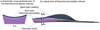 |
Fig. 1 The thermoformed plantar orthosis on which the geometry of the 3D-printed foot orthosis was based a) schematic cross-section view b) Photo view. This orthosis was prescribed for the treatment of plantar fasciitis symptoms. |
2.2 3D scan of plantar orthosis
In order to create a 3D-printed plantar orthosis with the same geometry as a the thermoformed one, a 3D scan of the patient's existing orthosis was conducted. This scan was performed using an Atos GOM 3D scanner. Following the acquisition of the STL file, the surfaces were reconstructed through a reverse engineering operation on Catia V5 software. This reverse engineering generates the volume of the thermoformed orthosis. Thereafter pores will be added to this volume (volume suppression) to obtain the 3D-printed orthosis. This reverse engineering is obtained by the next steps:
Isolation of the upper points of the orthosis (those in contact with the foot), best fit of a surface to this point cloud.
Identification of the upper boundary curve of the upper surface.
Isolation of the lower points of the orthosis (those in contact with the shoe), best fit of a surface to this point cloud.
Identification of the lower boundary curve of the lower surface.
Creation of a multi-section surface between the upper and lower boundary curves
2.3 Material stiffness analysis of the components of thermoformed plantar orthosis
The stiffness of each material comprising the orthosis was quantified. Indeed, stiffness was prepared for hardness in this study because it better reflects structural behavior. The orthosis comprised three layers: a pink layer, a blue layer and a black layer (leather) (Fig. 1). The pink layer was composed of EVA, the blue layer was thermoformed plastic, and the black layer was made of leather. Given that the blue and black layers are always present together in the orthosis, they will be characterized together as a “single material”. Thus, only one stiffness will be determined for sum of these two layers. Hence, we have streamlined the orthosis's composition by delineating two different mechanical materials: the foam component (pink layer) and the covering element (blue + black layers).
The experimental tests consisted of static compression with increasing depth. Four samples were tested: foam component, covering element, the assembly by glue of these two components and 3D printed sample in TPU. The four samples, 30 mm in diameter, were successively placed between two compression plates. The force (N) exerted on the samples was quantified using a multicomponent dynamometer Kistler 9257b with an acquisition frequency of 100 Hz.
The materials used in the thermoformed plantar orthosis are plastic materials with viscoelastic behavior. The objective of these tests is to characterize only the elastic part of the material behavior and to disregard the viscous aspect. To achieve this, the compression machine is programmed to execute nine successive depth-stages. Due to the viscous nature of the materials tested, once the compression depth is reached, and the displacement is stopped, the force decreases and stabilizes after a few seconds (Fig. 2). For the nine depth-stage, after the force stabilization, the mean force of the compression has been calculated. Thereafter, a force/depth graph is thus obtained with nine points (Fig. 2). Thereafter, only the last five points are considered. We then best fit at least min squares a straight line, using the Hooke's Law for springs, equation (1).
 (1)
(1)
With F the resulting force, k the modeled stiffness of the sample, δth the theoretical depth and δ0 the abscissa at the origin corresponding to the sample contact search error. The real depth δreal of each compressive test is the result of δth - δ0. The stiffness for each step was calculated using equation (2).
 (2)
(2)
With i the increment Fi the measured resultant force and δth i the theoretical compression depth of each step. The ki were then averaged and the standard deviation is computed using the five values of stiffness.
Four compression tests have been conducted:
Foam component (pink layer). The tested component has a thickness of 8 mm, and the depth-stage is 0.6 mm to reach a final depth of 3 mm.
Covering (blue + black layers). The tested component has a thickness of 2.23 mm, and the depth-stage is 0.1 mm to reach a final depth of 0.5 mm.
Sum of both (pink + blue + black layers). The depth-stage is 0.6 mm to reach a final depth of 3 mm.
3D-printed equivalent sample in TPU (see Sect. 2.4).
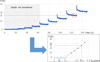 |
Fig. 2 Example of processing compression test results. |
2.4 Porosity design to replicate materials of thermoformed plantar orthosis
Following the estimation of the stiffness of the two materials comprising the thermoformed orthosis (pink layer and blue + black layer), a challenge was to reproduce them using a single material. The selected material was the thermoplastic polyurethane (TPU) because it is a recyclable material that is widely used in 3D filament printing due to its favorable balance of flexibility, strength and good durability, but the proposed method may be applied with a wide range of TPU like those presented in [31]. The challenge was to reproduce two materials with only one. The TPU modulus of elasticity is approximately 26 MPa. In comparison, ethylene vinyl acetate (EVA, pink layer) has a Young's modulus of only 8.8 MPa [32], which is considerably lower than that of TPU. To reduce this stiffness and approach that of EVA, pores were incorporated into TPU to soften it.
Selected pores are cylinders whose axes are distributed on a face-centered square pattern (Fig. 3). Two different patterns are defined, one for each identified material of the thermoformed orthosis (pink layer and blue + black layer). The size of pores is defined to obtain a stiffness equivalent to the measured materials of thermoformed orthosis. A finite element analysis (FEA) was conducted to determine the pore dimensions within the equivalent structure of the covering layer (blue + black layers). The simulated geometry consisted of a quarter-cylinder with a radius of 20 mm and a thickness of 3.53 mm (Fig. 3). The model was discretized using first-order tetrahedral elements, with a maximum mesh size of 0.1 mm to ensure at least three elements across the thinnest sections of the geometry. Boundary conditions included sliding constraints applied to three faces, while a prescribed displacement of 0.2 mm was imposed to simulate the compression depth. Thereafter, the reactive force at the prescribed displacement modes is calculated. Figure 3b illustrates the obtained Von Mises stress in the realized simulations. A similar approach was used to determine the pores geometries of the foam component (pink layer).
After that, rectangles were modelled to implement our porosity. Thus, two patterns are defined (Fig. 4):
The equivalent of the foam component (pink layer). The side of the pattern square is 4.8 mm and the radius of the cylindrical pores is 1.55 mm.
The equivalent of the covering (blue + black layers). The side of the pattern square is 4 mm and the radius of the cylindrical pores is 1.33 mm.
To generate the 3D-printed plantar orthosis, three supplementary layers were added to improve it (Fig. 4):
Upper surface (1 mm). It is a fully dense layer to prevent the foot from coming into contact with pores.
Intermediate surface (0.3 mm). It is a fully dense layer to ensure the material continuity between the covering and foam layers.
Lower surface (0.5 mm). It is a fully dense layer to ensure appropriate contact between the plantar orthosis and the insole of the shoe.
It is interesting to note that the 3D-printed orthoses are made entirely of TPU. No other layer is added to them.
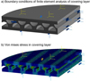 |
Fig. 3 Finite element analysis of the equivalent structure of the covering layer (blue + black layers) a) Boundary conditions b) Von Mises stress under a compression depth of 0.2 mm. |
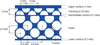 |
Fig. 4 Organization and pattern of the pores in the 3D-printed plantar orthosis. The radius of the cylinders in the foam part is 1.55 mm and 1.33 mm in the covering part. The foam has no height value in this diagram because it is the variable component of the orthosis. |
2.5 Porosity design validation
A compressive test is carried out to validate that the pore geometry previously defined for 3D-printed orthosis exhibits the same compressive behavior as thermoformed one. For this, a sample of 30 mm of diameter is manufactured and subjected to compression testing. This sample was made using the pores geometry of Figure 4 condition as plantar orthosis, with each layers (pink foam and covering) bonded together. FDM printing is chosen to stay in an affordable price of equipment. The printer utilized was an Ultimaker S3, equipped with an AA 04 nozzle. The material employed was Blue TPU 95A. The print density was set to 100%, with a zigzag pattern. The print temperature was maintained between 215 and 230 °C.
The parameters employed for these compressive tests were identical to those utilized for the characterization of the stiffness of the plantar orthosis materials. The depth-stage is 0.6 mm with 5 stages to reach a final depth of 3 mm.
2.6 Transverse isotropy study
To improve the performance of the 3D-printed plantar orthosis, mechanical isotropy is introduced in the orthosis. Two objectives are sought (Fig. 5a):
Reduce the flexural stiffness around the transverse axis. The purpose is to reduce the resistance when the foot is rolled out along its longitudinal axis.
increase the flexural stiffness around the longitudinal axis. The purpose is to increase the support provided by the orthosis to the plantar arch.
To achieve these two purposes, the cylinders forming the pores of the foot orthosis are oriented along the transverse axis. Fig. 5b) illustrates the obtained 3D-printed plantar orthosis.
Thereafter, to quantify the isotropy of proposed pattern (Fig. 4), three-point bending tests were used (Fig. 6). Two samples measuring 100 mm in length, 30 mm in width, and 11.57 mm in height were 3D-printed with the same parameters as previous sample. The thickness of the pink foam imitation was 7.54 mm (corresponding to the thickest possible part of the foot orthosis). The first sample exhibited a longitudinally oriented porosity pattern, while the second exhibited a transversely oriented porosity pattern (This is the sample shown in Fig. 6). A control sample of thermoformed plantar orthosis with each material bonded together (pink foam, blue and black layers) was made and laser cut to have the same length and width as 3D print samples. The thickness of the three samples was the same. The bending test has a depth-stage of 1.5 mm, with 6 stages to reach a final depth of 10.5 mm. Like for compression tests, the force (N) exerted on the samples was quantified using a dynamometer Kistler with an acquisition frequency at 100 Hz. The distance between supports was set at 70 mm.
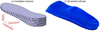 |
Fig. 5 a) Orientation of pores in the plantar orthosis (the diameter of the hole pores and the pattern size are increased relative to the real ones used for the 3D-printed orthosis for the readability of the figure), b) Photo of a manufactured 3D-printed orthosis. |
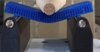 |
Fig. 6 Three-point bending test. |
2.7 Fatigue test
In order to estimate the behavior of our 3D-printed TPU plantar orthosis over time, fatigue tests were conducted. These tests were conducted on a cylindrical sample with the pores pattern (Fig. 4) of the 3D-printed orthosis. A test bench was constructed for the purpose of conducting these tests, with the capability of being adapted to a machine controlled in rotation speed. An eccentric, driven by the rotary motor of a Vernier FV3 milling machine, applies an alternative force to a flexible beam to which a compression system is attached, thereby exerting a force on the sample to be tested (Fig. 7). The dimensions of the beam and the eccentric value were calculated in order to enable the application of a cyclical force 5 to 100 N to a sample (these values were verified using the dynamometer). The diameter of the sample is 2.2 cm, which equates to a maximal pressure of approximately 25 N/cm (average step pressure [33]).
An individual is classified as sedentary when they accumulate less than 5,000 steps per day, and as active when they exceed 10,000 steps per day [31]. We therefore decided to place ourselves between these two values, at around 7,000 steps per day, or 3,500 for one foot. A frequency of 4 Hz was thus established, allowing for the simulation of a day's walking in approximately 14 min of fatigue test. The total duration of the fatigue test was established at 84 h which is equivalent to one year of use (the time at which the orthosis would typically be replaced). The initial stiffness of the sample was measured and then subsequently after fatigue for 15 min, 3 h and 30 min, 7 h, 14 h, 42 h and 84 h. The stiffness was measured using the same method as for the compression tests, with a depth-stage of 0.6 mm and 5 stages to reach a final depth of 3 mm.
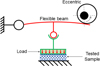 |
Fig. 7 Developed fatigue test bench. |
2.8 Test of the 3D print orthosis on a patient
Test was performed on a patient suffering from plantar fasciitis on the right foot, she was a 20-year-old woman weighing 56 kg. In order to observe the effects of the 3D-printed orthosis, two tests were carried out:
The oscillations in the center of pressure were measured using stabilograms produced with a FUSYO 3 pressure plate at a frequency of 40 Hz. The measurement is taken barefoot.
The “two steps” protocol [34,35] was measured using a WIN-TRACK force platform with a frequency of 200 Hz. This protocol is used to improve the repeatability of baropodometric measurements. Its aim is to limit recording biases related to variations in walking speed. In concrete terms, the patient starts to walk two steps before the platform: the first step is taken before the platform, and the second step is taken on the platform. Thus, even if the patient is still in the acceleration phase, strictly replicating this protocol during successive assessments ensures better reproducibility of baropodometric measurements. Two passes are performed, one barefoot and the other with orthoses (held under the foot by a sock).
A visual analog scale was employed to evaluate the level of pain and discomfort experienced in overall. This visual analog scale is an adaptation for plantar orthosis of a questionnaire originally designed for orthopedic shoes [36]. However, in this study only the overall pain level was exploited. The distance at which the cursor was placed was measured and expressed as a percentage. Additionally, a questionnaire was administered to evaluate the patient's experience with the orthosis, assessing its efficacy, safety, and satisfaction.
All of the aforementioned tests were conducted at the initial fitting of the orthosis (T0) and again after a six-week period of use (T6).
Furthermore, the eligible patients were informed about the study and the protocol design. They were also well informed about the advantages and disadvantages of their participation. The experiment is included in the treatment delivered by podiatrist from Podiatry school of Aix-MArseille Univerity. All subjects provided their written informed consent to participate in the study and publication of the report.
2.9 Statistical analysis
All data was processed using Microsoft Excel (2016) and statistical analysis was carried out using Jamovi software. A Mann-Whitney test was used to compare compressive stiffness between the TPU sample with porosity and the thermoformed orthosis sample. A Student's t test was used to analyse the difference in flexural stiffness between the sample with longitudinal porosity and the sample with transverse porosity. The significance level was set at 5%.
3 Results
3.1 Compression tests
Experimental studies indicate that the stiffness of the pink foam was found to be 33.71 N/mm ( ± 3.69 N/mm), while the stiffness of the covering was measured at 1306.11 N/mm ( ±481.12 N/mm). These values were incorporated into the finite element (FE) analysis. Once the optimal porosity had been identified (Fig. 4), allowing for a stiffness comparable to that previously observed. The FEA-identified geometry is printed and then undergoes identical compression testing (Fig. 8a). Test carried out on 3D printed sample exhibited a stiffness of 40.21 N/mm ( ± 0.67 N/mm), while the thermoformed orthosis sample demonstrated a stiffness of 42.81 N/mm ( ± 3.96 N/mm) (Fig. 8b). No statistically significant difference was observed between the stiffness of the TPU sample and that of the thermoformed orthosis sample (p = 0.53).
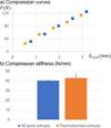 |
Fig. 8 Comparison of stiffness between 3D printed and thermoformed plantar orthosis a) compression graphical b) compression stiffness comparison. |
3.2 Transverse isotropy study: bending test
The flexural curve of the three tested materials (Fig. 9a) exhibits a significantly different stiffness. The tests revealed that when the porosity was oriented longitudinally in the specimen, the stiffness was measured at 8.37 N/mm ( ±1.56 N/mm), while when it was oriented transversally, the stiffness was 5.01 N/mm ( ±0.82 N/mm). A statistically significant difference in stiffness was observed between the specimen with longitudinal porosity and the specimen with lateral porosity (p < 0.05), thereby confirming the transverse isotropic property of the 3D-printed orthosis (Fig. 9b).
The flexural stiffness of the thermoformed orthosis sample was found to be 2.54 N/mm ( ± 0.21 N/mm), which is approximately half that of the 3D-printed TPU sample with transverse porosity.
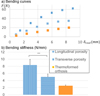 |
Fig. 9 Results of the three-point bending test, a) Force/depth graphic of the three tested sample, b) histogram comparing the stiffness of three tested sample. |
3.3 Fatigue tests
Following 84 h of fatigue, which is the equivalent of a year's use, visual analysis demonstrated that the upper and lower surfaces of the sample remained intact (Figs. 10a and 10b). However, the internal structure exhibited signs of damage, with the collapse of multiple trusses (Fig. 10b). The results of the fatigue tests indicate a notable decline in the stiffness of the base material over the course of the experiment, from an initial stiffness value of 25.94 N/mm ( ± 3.18 N/mm) to 4.65 N/mm ( ± 5.05 N/mm) after 42 h (equivalent to approximately six months). A 64% increase in stiffness was observed between 42 and 84 h.
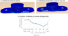 |
Fig. 10 a) cylindrical sample for fatigue test before the test, b) Cylindrical sample at the end of the fatigue test, c) Evolution of stiffness in function of fatigue time. The scale located at the apex of the abscissa correlates with the actual duration of fatigue, whereas the scale situated at the base correlates with the corresponding duration in terms of wear. |
3.4 Patient results
The mean pain score reported by the patient at T0 was 56%, which can be considered a relatively high level of discomfort (Fig. 11). However, following a six-week period, the level of pain experienced decreased to below 10%. A similar pattern was observed for pain and discomfort in the arch of the foot, with approximately 50% pain and discomfort at T0 and less than 10% at T6. The instability score decreased from approximately 30% to around 10%. The 3D orthosis thus had a beneficial effect on the patient's experience of all these variables.
In terms of statokinesigram analysis of balance (Fig. 12), it can be observed that at T0 the patient's center of pressure was situated to the right (pathologic foot) and demonstrated a notable degree of instability (as indicated by the large area of the center of pressure). At T6, the centers of pressure demonstrated a more centralized position with a markedly reduced area. These findings suggest an enhancement in balance following six weeks of wearing the 3D-printed orthosis, which aligns with the patient's reported experience.
The results of the dynamic study (Fig. 13) of the average forces exerted by the right foot demonstrate a greater peak force during the initial contact phase when orthosis is worn compared to when no orthosis is worn, whether at T0 or T6 (similar results are observed in left foot). This suggests an action of the orthosis on the force induced on the heel. No notable difference was observed during the pre-swing phase, apart from a slight time lag induced by the difference in force during the damping phase.
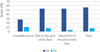 |
Fig. 11 Assessment of pain, discomfort and instability when wearing the 3D print plantar orthosis. |
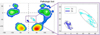 |
Fig. 12 statokinesigram analysis, pressure map at T0 and variation of center of pressure at T0 and T6. |
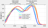 |
Fig. 13 The “two steps” protocol measured one the right foot (pathologic). |
4 Discussion
The objective of this study was to develop a 3D-printed orthosis constructed from a single, recyclable material that exhibits the same characteristics as a thermoformed orthosis while offering enhanced benefits for the health of the podiatrists who manufacture it. One of the filaments which generates the fewestof volatile organic compounds and toxic gases [37]. To the best of our knowledge, no study has yet investigated this possibility. The majority of existing studies have employed a method whereby the TPU base is 3D-printed and the remaining components are subsequently attached by gluing [23]. However, our findings demonstrate that it is feasible to create a complete plantar orthosis with distinct functionalized components in a single print by incorporating specific pores for each location. The plantar orthosis would therefore be entirely recyclable, as it would be composed solely of TPU. It would then be feasible to melt the used orthosis to create new spools of thread for the 3D printer and print new orthosis. This process would significantly diminish the environmental impact of orthopedic orthosis, from design to recycling.
In this study, the geometry and mechanical properties of the 3D-printed orthosis were based on those of a patient-specific thermoformed orthosis. Nevertheless, in the future, the objective will be not to base the design on pre-existing geometries, but rather to utilize patient data to inform the design of the orthosis. The study by Hsu et al. (2022) demonstrates the feasibility of 3D-printing plantar orthosis directly from data collected by podiatrists using diverse methodologies.
One of the major additions brought by the geometry of the porosity of the 3D printed foot orthosis is its transverse isotropic behavior. The results confirm this behavior by showing a significant difference in flexion stiffness depending on the orientation of the porosity. Thus, beyond the compression stiffness allowing sufficient comfort and support of the foot, the longitudinal flexion stiffness helps to contribute a little more to the support of the foot while allowing a natural rolling of the foot. We observe a difference in flexion stiffness between the 3D printed and thermoformed samples. This difference may be explained by two points:
The indentation of the two support cylinders in the pink EVA foam during the three-point-bending test.
Flexion tests were conducted on a sample with the maximum thickness of the thermoformed plantar orthosis. If the tests had been carried out without foam (corresponding to the front part of the plantar orthosis), it is highly probable that the stiffness in flexion would have been greater than that of the 3D-printed orthosis.
Consequently, the observed difference in flexion must be contextualised in accordance with the location of the test on the orthosis and the thickness of each material.
Fatigue tests show that the 3D-printed orthosis solution appears feasible for a one-year lifespan. However, regular local deterioration of the trusses between the cylinders (Fig. 10c) leads to an almost linear decrease in compressive stiffness over the first six months (a fivefold decrease). After this phase, a recovery in compressive stiffness is observed thanks to the direct contact of the material at the top and bottom of the pores. These results therefore suggest that the porosity pattern should be further optimized to improve the fatigue resistance of our orthoses even more.
The patient study demonstrates a relatively favorable trajectory, with a corrective impact of the orthosis after six weeks of utilization, in regard to both pain and balance. Similar effects were observed for patient-specific thermoformed foot orthoses, with a significant reduction in pain and a significant increase in quality of life after 1 month [38]. A dynamic analysis of the forces exerted during ambulation unambiguously demonstrates the corrective effect of the 3D-printed orthosis, with a markedly elevated peak of force on the heel during the cushioning phase, thereby providing substantial relief for plantar fasciitis. However, it would be beneficial to conduct a longitudinal study over the product's entire life cycle to ascertain whether, despite this reduction in stiffness, the orthosis continues to fulfil its function of supporting the medial arch and heel. The results of pain and discomfort reduction presented here on a patient are comparable to those obtained in the literature with thermoformed plantar orthosis [12,39,40].
Our first validation of 3D orthoses presents a clinical case study. However, we studied the effects of our 3D-printed orthosis on just one patient. These initial positive results constitute a proof of concept and pre-validation, which are a prerequisite for a larger study. Future work will consist of extending the methods to a larger cohort of patients in order to obtain statistically reliable results and provide clear validation.
5 Conclusion
In the context of sustainable development and with a view to more ecologically responsible production and the health of podiatrists, this study demonstrates that it is feasible to 3D-print a plantar orthosis utilizing a single recyclable material in which pores have been incorporated to functionalize the different areas of the orthosis according to the patient's requirements. The orthosis is therefore fully recyclable, thus circumventing the health issues that podiatrist face in the production of such devices. A proof of concept on one patient showed interesting results, but additional studies on a larger cohort of patients are necessary to validate these results. The five mains' contributions of this study are:
Design of a 3D-printed plantar orthosis composed of a single, recyclable material
The geometry of a common thermoformed orthosis and the mechanical behavior of each material constituting it are measured
Specific isotropic pores are calculated using FEA to reproduce the mechanical behavior of thermoformed orthosis materials
An initial trial with one patient was conducted, yielding promising outcomes
A fatigue test was conducted, showing that the defined solution appears to withstand one year of use
This study paves the way to This study paves the way for the development of custom-made foot orthotics with more complex modulation of local mechanical properties depending on the pathology being treated.
Funding
This study was supported and funded by the French Carnot STAR Institute.
Conflicts of interest
The authors have nothing to disclose.
Data availability statement
The data of this article are available on demand.
Author contribution statement
Conceptualization, Chaves-Jacob, Milan, Griffon, Le Goff and Dousset; Methodology, Chaves-Jacob, Milan, Griffon, Le Goff and Dousset; Software, Chaves-Jacob, Balandier, Mesure; Validation, Chaves-Jacob, Milan, Griffon, Le Goff and Dousset; Formal Analysis, Balandier, Mesure, Milan and Dousset; Investigation, Chaves-Jacob, Balandier, Mesure, Milan, Griffon, Le Goff and Dousset; Resources, Chaves-Jacob, Griffon, Le Goff and Dousset; Data Curation, Chaves-Jacob, Mesure, Milan, Griffon, Le Goff and Dousset; Writing – Original Draft Preparation, Chaves-Jacob, Balandier, Milan and Dousset; Writing – Review & Editing, Chaves-Jacob, Milan and Dousset; Visualization, Chaves-Jacob, Mesure, Balandier, Milan and Dousset; Supervision, Chaves-Jacob, Milan, Griffon, Le Goff and Dousset; Project Administration, Chaves-Jacob, Milan, Griffon, Le Goff and Dousset; Funding Acquisition, Chaves-Jacob, Milan and Dousset.
References
- K.B. Landorf, H.B. Menz, Plantar heel pain and fasciitis, BMJ Clin. Evid. 2008, 1111 (2008) [Google Scholar]
- A.J. Rosenbaum, J.A. DiPreta, D. Misener, Plantar heel pain, Med. Clin. North Am. 98, 339–352 (2014) [Google Scholar]
- T. Aldridge, Diagnosing heel pain in adults, Am. Fam. Physician, 70, 332–338 (2004) [Google Scholar]
- H. Lemont, K.M. Ammirati, N. Usen, Plantar fasciitis, J. Am. Podiatr. Med. Assoc. 93, 234–237 (2003) [Google Scholar]
- P. Beeson, Plantar fasciopathy: revisiting the risk factors, Foot Ankle Surg. 20, 160–165 (2014) [Google Scholar]
- D.L. Riddle, M. Pulisic, P. Pidcoe, R.E. Johnson, Risk factors for plantar fasciitis: a matched case-control study, J. Bone Jt. Surg.-Am. 85, 872–877 (2003) [Google Scholar]
- J. Woolnough, Tennis heel, Med. J. Aust. 2, 857 (1954) [Google Scholar]
- S. Milner, Common disorders of the foot and ankle, Surg. Oxf. 24, 382–385 (2006) [Google Scholar]
- H. Chen, D. Sun, Y. Fang, S. Gao, Q. Zhang, I. Bíró, V. Tafferner-Gulyás, Y. Gu, Effect of orthopedic insoles on lower limb motion kinematics and kinetics in adults with flat foot: a systematic review, Front. Bioeng. Biotechnol. 12, 1435554 (2024) [Google Scholar]
- G. Kogler, S. Solomonidis, J. Paul, Biomechanics of longitudinal arch support mechanisms in foot orthoses and their effect on plantar aponeurosis strain, Clin. Biomech. 11, 243–252 (1996) [Google Scholar]
- G.F. Kogler, F.B. Veer, S.E. Solomonidis, J.P. Paul, The influence of medial and lateral placement of orthotic wedges on loading of the plantar aponeurosis. An in vitro study, J. Bone Jt. Surg. 81, 1403–13 (1999) [Google Scholar]
- S. Moyne-Bressand, C. Dhieux, E. Dousset, P. Decherchi, Effectiveness of foot biomechanical orthoses to relieve patients suffering from plantar fasciitis : is the reduction of pain related to change in neural strategy?, BioMed Res. Int. 2018, 1–17 (2018) [Google Scholar]
- C.Z.-H. Ma, D.W.-C. Wong, A.H.-P. Wan, W.C.-C. Lee, Effects of orthopedic insoles on static balance of older adults wearing thick socks, Prosthet. Orthot. Int. 42, 357–362 (2018) [Google Scholar]
- H. Chen, D. Sun, L. Gao, X. Liu, M. Zhang, Mechanical behavior of closed-cell ethylene-vinyl acetate foam under compression, Polymers, 16, 34 (2023) [Google Scholar]
- R.D.F.M. Taalman, Isoprene: background and issues, Toxicology, 113, 242–246 (1996) [Google Scholar]
- M. Bogdanffy, A biologically based risk assessment for vinyl acetate-induced cancer and noncancer inhalation toxicity, Toxicol. Sci. 51, 19–35 (1999) [Google Scholar]
- T.T. Meng, Volatile organic compounds of polyethylene vinyl acetate plastic are toxic to living organisms, J. Toxicol. Sci. 39, 795–802 (2014) [Google Scholar]
- B.R. Da Costa, E.R. Vieira, Risk factors for work‐related musculoskeletal disorders: a systematic review of recent longitudinal studies, Am. J. Ind. Med. 53, 285–323 (2010) [Google Scholar]
- K.B. Landorf, A.M. Keenan, Efficacy of foot orthoses. What does the literature tell us? J. Am. Podiatr. Med. Assoc. 90, 149–158 (2000). PMID: 10740997 [Google Scholar]
- D.R. Bonanno, G.S. Murley, S.E. Munteanu, K.B. Landorf, H.B. Menz, Effectiveness of foot orthoses for the prevention of lower limb overuse injuries in naval recruits: a randomised controlled trial, Br. J. Sports Med. 52, 298–302 (2018) [Google Scholar]
- K. Wang, C. Lu, R. Ye, W. He, X. Wei, Y. Li, X. Pan, C. Zhao, X. Yu, Research and development of 3D printing orthotic insoles and preliminary treatment of leg length discrepancy patients, Technol. Health Care, 28, 615–624 (2020) [Google Scholar]
- M. Davia-Aracil, J.J. Hinojo-Pérez, A. Jimeno-Morenilla, H. Mora-Mora, 3D printing of functional anatomical insoles, Comput. Ind. 95, 38–53 (2018) [Google Scholar]
- C.-Y. Hsu, C.-S. Wang, K.-W. Lin, M.-J. Chien, S.-H. Wei, C.-S. Chen, Biomechanical analysis of the FlatFoot with different 3D-printed insoles on the lower extremities, Bioengineering, 9, 563 (2022) [Google Scholar]
- S. Telfer, J. Pallari, J. Munguia, K. Dalgarno, M. McGeough, J. Woodburn, Embracing additive manufacture: implications for foot and ankle orthosis design, BMC Musculoskelet Disord. 13, 84 (2012). PMID: 22642941; PMCID: PMC3502337 [Google Scholar]
- C.E. Dombroski, M.E. Balsdon, A. Froats, The use of a low cost 3D scanning and printing tool in the manufacture of custom-made foot orthoses: a preliminary study, BMC Res. Notes. 7, 443 (2014). PMID: 25015013; PMCID: PMC4114407 [Google Scholar]
- R.K. Chen, Y. Jin, J. Wensman, A. Shih, Additive manufacturing of custom orthoses and prostheses—a review, Addit Manuf. 12, 77–89 (2016) [Google Scholar]
- G. Desmyttere, S. Leteneur, M. Hajizadeh, J. Bleau, M. Begon, Effect of 3D printed foot orthoses stiffness and design on foot kinematics and plantar pressures in healthy people, Gait & Posture, 81, 1–17(2020) [Google Scholar]
- A. Daryabor, T. Kobayashi, H. Saeedi, S.M. Lyons, N. Maeda, S.S. Naimi, Effect of 3D printed insoles for people with flatfeet: a systematic review, Assist. Technol. 35, 169–179 (2023) [Google Scholar]
- K. Ilavarasi, Effectiveness of 3D Foot Scanner Designed and Fabricated Customized Foot Insole in the Management of Children with Flat Foot, Thèse de doctorat. JKK Muniraja Medical Research Foundation, Komarapalayam, 2018 [Google Scholar]
- S. Mo, S.H.S. Leung, Z.Y.S. Chan, L.K.Y. Sze, K.M. Mok, P.S.H. Yung, R. Ferber, R.T.H. Cheung, The biomechanical difference between running with traditional and 3D printed orthoses, J. Sports Sci. 37, 2191–2197 (2019) [Google Scholar]
- C. Tudor-Locke, D.R. Bassett, How many steps/day are enough?: preliminary pedometer indices for public health, Sports Med. 34, 1–8 (2004) [Google Scholar]
- L.-C. Jia, Z.-H. Jiao, D.-X. Yan, Z.-M. Li, Octadecylamine-grafted graphene oxide helps the dispersion of carbon nanotubes in ethylene vinyl acetate, Polymers, 9, 397 (2017) [Google Scholar]
- M.C. Iacob, D. Popescu, D. Petcu, R. Marinescu, Assessment of the flexural fatigue performance of 3D-printed foot orthoses made from different thermoplastic polyurethanes, Appl. Sci. 13, 12149 (2023) [Google Scholar]
- M. van der Leeden, J.H. Dekker, P.C. Siemonsma, S.S. Lek-Westerhof, M.P. Steultjens, Reproducibility of plantar pressure measurements in patients with chronic arthritis: a comparison of one-step, two-step, and three-step protocols and an estimate of the number of measurements required, Foot Ankle Int. 25, 739–744 (2004) [Google Scholar]
- S.A. Bus, A. de Lange, A comparison of the 1-step, 2-step, and 3-step protocols for obtaining barefoot plantar pressure data in the diabetic neuropathic foot, Clin. Biomech (Bristol), 20, 892–899 (2005) [Google Scholar]
- M.J. Jannink, J. de Vries, R.E. Stewart, J.W. Groothoff, G.J. Lankhorst, Questionnaire for usability evaluation of orthopaedic shoes: construction and reliability in patients with degenerative disorders of the foot, J. Rehabil. Med. 36, 242–248 (2004) [Google Scholar]
- A.H. Khoshakhlagh, S Al Sulaie, S. Yazdanirad, A. Gruszecka-Kosowska, A global evaluation of exposure to pollutants in 3D printing: a systematic review and meta-analysis, J. Hazard. Mater. Adv. 20, 100931 (2025) [Google Scholar]
- M. Nakhaee, M.A. Mohseni-Bandpei, M.E. Mousavi, A. Shakourirad, R. Safari, R.V. Kashani, R. Mimar, H. Amiri, M. Nakhaei, The effects of a custom foot orthosis on dynamic plantar pressure in patients with chronic plantar fasciitis: a randomized controlled trial, Prosthet. Orthot. Int. 47, 241–252 (2023) [Google Scholar]
- S.C. Lin, C.P.C. Chen, S.F.T. Tang, A.M.K. Wong, J.H. Hsieh, W.P. Chen, Changes in windlass effect in response to different shoe and insole designs during walking, Gait. Posture 37, 235–241 (2013) [Google Scholar]
- D.T. Fong, K.Y. Pang, M.M. Chung, A.S. Hung, K.M. Chan, Evaluation of combined prescription of rocker sole shoes and custom-made foot orthoses for the treatment of plantar fasciitis, Clin. Biomech. (Bristol, Avon) 27, 1072–1077 (2012) [Google Scholar]
Cite this article as: J. Chaves-Jacob, E. Balandier, J. Mesure, J.-L. Milan, P. Griffon, C. L Goff, E. Dousset, Development of a single porous material 3D-printed plantar orthosis to improve recycling and preserve the health of podiatrists, Mechanics & Industry 27, 27 (2026), https://doi.org/10.1051/meca/2026026
All Figures
|
Fig. 1 The thermoformed plantar orthosis on which the geometry of the 3D-printed foot orthosis was based a) schematic cross-section view b) Photo view. This orthosis was prescribed for the treatment of plantar fasciitis symptoms. |
| In the text | |
|
Fig. 2 Example of processing compression test results. |
| In the text | |
|
Fig. 3 Finite element analysis of the equivalent structure of the covering layer (blue + black layers) a) Boundary conditions b) Von Mises stress under a compression depth of 0.2 mm. |
| In the text | |
|
Fig. 4 Organization and pattern of the pores in the 3D-printed plantar orthosis. The radius of the cylinders in the foam part is 1.55 mm and 1.33 mm in the covering part. The foam has no height value in this diagram because it is the variable component of the orthosis. |
| In the text | |
|
Fig. 5 a) Orientation of pores in the plantar orthosis (the diameter of the hole pores and the pattern size are increased relative to the real ones used for the 3D-printed orthosis for the readability of the figure), b) Photo of a manufactured 3D-printed orthosis. |
| In the text | |
|
Fig. 6 Three-point bending test. |
| In the text | |
|
Fig. 7 Developed fatigue test bench. |
| In the text | |
|
Fig. 8 Comparison of stiffness between 3D printed and thermoformed plantar orthosis a) compression graphical b) compression stiffness comparison. |
| In the text | |
|
Fig. 9 Results of the three-point bending test, a) Force/depth graphic of the three tested sample, b) histogram comparing the stiffness of three tested sample. |
| In the text | |
|
Fig. 10 a) cylindrical sample for fatigue test before the test, b) Cylindrical sample at the end of the fatigue test, c) Evolution of stiffness in function of fatigue time. The scale located at the apex of the abscissa correlates with the actual duration of fatigue, whereas the scale situated at the base correlates with the corresponding duration in terms of wear. |
| In the text | |
|
Fig. 11 Assessment of pain, discomfort and instability when wearing the 3D print plantar orthosis. |
| In the text | |
|
Fig. 12 statokinesigram analysis, pressure map at T0 and variation of center of pressure at T0 and T6. |
| In the text | |
|
Fig. 13 The “two steps” protocol measured one the right foot (pathologic). |
| In the text | |
Current usage metrics show cumulative count of Article Views (full-text article views including HTML views, PDF and ePub downloads, according to the available data) and Abstracts Views on Vision4Press platform.
Data correspond to usage on the plateform after 2015. The current usage metrics is available 48-96 hours after online publication and is updated daily on week days.
Initial download of the metrics may take a while.