| Issue |
Mechanics & Industry
Volume 21, Number 6, 2020
|
|
|---|---|---|
| Article Number | 624 | |
| Number of page(s) | 12 | |
| DOI | https://doi.org/10.1051/meca/2020098 | |
| Published online | 07 January 2021 | |
Regular Article
The influence of the shaft angle value on the normal stress and displacement repartition by bevel gear pairs − a TCA investigation
Department of Mechanical Engineering, University of Debrecen, 4031 Debrecen, Ótemető str. 2-4., Hungary
* e-mail: This email address is being protected from spambots. You need JavaScript enabled to view it.
Received:
24
September
2020
Accepted:
14
December
2020
Abstract
Five types of bevel gear pairs having straight teeth were designed to analyze the effect of the modification of the shaft angle. This angle is the parameter − subject of TCA. After the geometric design process and the creation and assembly of the CAD models, Tooth Contact Analysis (TCA) was performed in order to get the mechanical parameters focusing of the tooth roots of the connecting teeth. We repeated this process five times since the load torques were also changed. The received mechanical parameters on the teeth connection of the pinion and the driven gear were analyzed with taking in consideration all four-tooth root surfaces that limit the contacting teeth pair. Finally, we referred to the useful selection of the appropriate gear pair for the engineering application.
Key words: Tooth root / bevel gear / torque / TCA / shaft angle
© AFM, EDP Sciences 2021
1 Introduction
The bevel gears are used in many different engineer's constructions. The application of them is mainly found in the vehicle industry, robot industry, medical applications and other special engineer's areas. The main properties of these elements are the changing of turning direction between the elements and the application of different sum of pitch angles because of the cone establishments [1,2].
There are many publications in field of the bevel gear pairs having straight teeth [2–10].
The computer aided designing (CAD) of straight bevel gears manufactured by dual interlocking circular cutters, and the evaluation of this simulation of meshing and connection of the elements as well as finite element analysis are shown [2].
Because of the high forming load and serious die wear, the large diameter of the straight bevel gear is rarely to manufacture by forging. A new forming method is recommended to manufacture the straight bevel gear by a specific die with a flash and a boss. The forming load and die wear are considered as the optimization targets [4].
Based on the Tredgold's approximation, a transparent contact stress capacity model for straight bevel gears is developed. A bevel load factor could be defined which provides a kinetic connection between the real bevel gear and theoretical spur gear [5].
Considering the precessional bevel gears with a small shaft angle, a number of drives with oil and gas devices have been developed. Due to multi-pair tooth generating they have a higher load capacity in comparison with other types of gears, which provides a good drive operation [6].
The [7] paper deals with the development and the validation of an approach for the contact pattern evaluation in straight bevel gears within a pass/fail decision process. The developed method is based on blending vibration-based condition indicators with classification algorithms so as to distinguish adequate contact patterns from inaccurate pairs.
The purpose of the study presented in [8] is to present a clear essential thought for designing and investigating straight bevel gear made of compound material. Application of them in modern engineering practice includes the components of the elements, such as robotic arms, and this is especially obvious when metallic gears are incapable of coping with the lively requirements of the constructions.
The paper [10] shows two powerful optimization methods: the simulated annealing algorithm (SA) and the genetic algorithm (GA), that open up possibilities for advanced optimization. These, coupled with American Gear Manufacturers Association (AGMA) instructions lead to the mass reducing of straight bevel gear pair by considering the suitable design variables.
The aim of the TCA is the analysis of the significant mechanical parameters (stresses, deformations, etc.) on the teeth of the connecting elements by different loads (torque, moment). That is why the behaviour of the gear pairs could be simulated and pre-estimated before the real application. Certainly, the setting of the material type is also important.
This is a complex research because firstly the researcher has to design the geometric parameters of gear pairs considering the reference's recommendations. For this purpose new computer software has to be worked out in many cases or special gear designer software has to be bought. The following step is the CAD modelling and the assembling of the elements by the application of a CAD software. Once the surfaces and solid bodies are obtained, the TCA can start.
If the Σ = 90° sum of pitch angles arrangement is not solvable but angular shaft position is needed the shaft angle will have to be modified. In these special cases the appropriate tooth establishment is significant because of the conversation of given load. The gear setting is along the pitch cones that is why the sum of pitch angles is (Fig. 1) [1–7,12]. (1)
(1)
 |
Fig. 1 The geometry of bevel gear pairs having straight teeth by the shaft angle and fillet radiuses on the tooth roots [11]. |
2 Computer aided design of different bevel gear pairs
Five types of bevel gear pairs were designed. In geometrical aspects they are similar but only one parameter is the difference between them which is only the shaft angle. Knowing of the recommendations of the gear design references [1–8,12,13,15] the initial parameters could be set and the designing method could be selected. As a result, these pairs could be designed.
The geometric parameters of our-designed bevel gear pairs are presented on Table 1. The transmission ratio means the ratio of Number of teeth I and Number of teeth II. During the teeth connection two teeth are connected at the same time.
Firstly, all of the geometric parameters had to be determined by the help of the GearTeq software. This software is quite complex but it is important for the exact gear designing. Using of this program many types of gear pairs could be designed (bevel gears, tooth gears, gear racks, helical gears, worm gear drives, planetary gears, etc.) (Fig. 2).
After the geometric designing, the GearTeq can visualize the gear pair. If the geometric shape is acceptable the designed parameters could be saved into the Solidworks software (Fig. 3). The our-designed gear pair could be seen (CAD modelling) by the Solidworks software. The necessary tooth connecting simulations are to be done here to be before the TCA starts.
The designed gear pair's parameters.
 |
Fig. 2 The application of the GearTeq software for designing of bevel gear pairs (Σ = 70°). |
 |
Fig. 3 The designed bevel gear pair by Solidworks software (Σ = 70°). |
2.1 TCA analysis on the tooth roots by the modification of the shaft angle
After the geometric designing (CAD) the TCA could be done. The aim of this analysis is the determination of the mechanical parameters (stresses, deformations, strains, etc.) during the teeth connection by given loads before the real manufacturing [7,12,14–17].
The selected material was structural steel for both elements (Tab. 2).
The friction coefficient value was set µ = 0.15 because this can be considered an average value characteristic for steel. Dense meshing was used on the teeth contact zone (Fig. 4). Element size was 1 mm on this area. All fillet radiuses were set on 2.8 mm on the tooth roots.
The driven gear has all degrees of freedom blocked. Only one rotation freedom degree was permitted on the pinion. 900, 1500, 2000, 2500 and 3000 Nm torques were applied as a load torque on the pinion. This values were selected accordingly the geometric parameters, the material type and based on our experience. The effect of these loads on the tooth roots were analyzed (Fig. 5).
Both roots of the coupling teeth were analyzed on the pinion's and the driven gear's tooth according to Figure 5. The above mentioned torques were used in case of Gears I–V and analyzed the arising normal stresses and normal deformations.
Six coordinate systems had to be defined for the analysis:
-
one rotation coordinate system of the pinion around the axis of rotation,
-
one rotation coordinate system of the driven gear around the axis of rotation,
-
four coordinate systems on the tooth roots (by all fillet surfaces, axis ‘x’ is perpendicular on the fillet surface direction line and are situated in the symmetry plane of it).
The parameters of the selected structural steel.
 |
Fig. 4 The adoption of the FEM mesh. |
 |
Fig. 5 The analyzed tooth roots of the pinion and the driven gear. |
2.2 The analysis of the normal stresses
The distributions of the normal stress on the tooth roots could be seen on Figures 6–9 in case of Σ = 70° and M = 1500 Nm. Naturally, these analyzes were done for the other gear pairs.
The average results are summarized on the following charts for every tooth root individually for each torque (Fig. 10).
Based on Figure 10 the followings could be concluded:
-
the normal stress is being increased because of the enhancement of the torque,
-
the highest normal stress values are received on the Tooth root 1 on the pinion,
-
the normal stresses on Tooth root 2 is usually lower than on Tooth root 3,
-
the lowest normal stress values are received on the Tooth root 2 and Tooth root 3.
Summary charts considering each tooth root were drawn using the gained stress analysis data (Fig. 11). Based on Figure 11 the following statements can be done:
-
the highest normal stress values appear in case of Σ = 85° result,
-
the lowest normal stress values appear in case of Σ = 70° result, that is why this sum of pitch angle is recommended for designing if the construction is allowed,
-
a little wave could be considered on Tooth root 3 and 4 due to the higher growth of the normal stress
 |
Fig. 6 Normal stress' distributions on Tooth root 1 on the pinion (Σ = 70°, M = 1500 Nm). (a) M = 900 Nm, (b) M = 1500 Nm, (c) M = 2000 Nm, (d) M = 2500 Nm, (e) M = 3000 Nm. |
 |
Fig. 7 Distributions of the normal stress on Tooth root 2 on the pinion (Σ = 70°, M = 1500 Nm). (a) M = 900 Nm, (b) M = 1500 Nm, (c) M = 2000 Nm, (d) M = 2500 Nm, (e) M = 3000 Nm. |
 |
Fig. 8 Distributions of the normal stress on Tooth root 3 on the driven gear (Σ = 70°, M = 1500 Nm). (a) M = 900 Nm, (b) M = 1500 Nm, (c) M = 2000 Nm, (d) M = 2500 Nm, (e) M = 3000 Nm. |
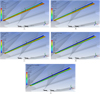 |
Fig. 9 Distributions of the normal stress on Tooth root 4 on the driven gear (Σ = 70°, M = 1500 Nm). (a) M = 900 Nm, (b) M = 1500 Nm, (c) M = 2000 Nm, (d) M = 2500 Nm, (e) M = 3000 Nm. |
 |
Fig. 10 Summary chart of the results of the normal stresses for each shaft angle. (a) Σ = 70°, (b) Σ = 75°, (c) Σ = 80°, (d) Σ = 85°, (e) Σ = 90°. |
 |
Fig. 11 Summary chart of the results of the normal stresses separately for every tooth root. (a) Tooth root 1, (b) Tooth root 2, (c) Tooth root 3, (d) Tooth root 4. |
2.3 The analysis of the normal deformations
The normal deformation's distributions on the tooth roots could be seen on Figure 12 in case of Σ = 70° and M = 1500 Nm. Naturally, the analyzes were done for the other bevel gears too.
The average results are summarized on charts for every tooth root individually for each torque (Fig. 13). Based on Figure 13 the following statements could be made:
-
the highest normal deformation values appear on the Tooth root 1 on the pinion. This value is prominently higher than the other values.
-
the lowest normal deformation values appear on the Tooth root 4 on the driven gear,
-
the normal deformations are continuously decreasing from the Tooth root 1 to the Tooth root 4,
-
the normal deformation values are continuously increasing because the effect of the increscent torque.
Summary charts referring to each tooth roots were done because of stress analysis (Fig. 14).
Based on Figure 14 the following statements could be made:
-
in case of Tooth root 1:
∘ the highest normal deformation values appear in case of Σ = 90°,
∘ the lowest normal deformation values appear in case of Σ = 70°,
∘ the Σ = 80° result is situated on the middle approximately,
∘ the normal deformation values are almost equal in case of Σ = 70° and Σ = 75° sum of pitch angles.
-
in case of Tooth root 2:
∘ the highest normal deformation values appear in case of Σ = 85°,
∘ the lowest normal deformation's values appear in case of Σ = 90°,
∘ the Σ = 70° and Σ = 75° results are situated on the middle approximately,
∘ the normal deformation values are almost equal in case of Σ = 70° and Σ = 75° sum of pitch angles.
-
in case of Tooth root 3:
∘ the highest normal deformation values appear in case of Σ = 85°,
∘ the lowest normal deformation values appear in case of Σ = 70°,
∘ the Σ = 80° result is situated on the middle approximately.
-
in case of Tooth root 4:
∘ the highest normal deformation values appear in case of Σ = 70°,
∘ the lowest normal deformation values appear in case of Σ = 85° and Σ = 90° sum of pitch angles,
∘ the Σ = 80° result is situated on the middle approximately.
Knowing of the decided optimum purpose the appropriate bevel gear pair by the shaft angles could be selected accordingly Figures 11 and 14.
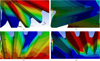 |
Fig. 12 Normal deformation's distributions on the tooth roots (Σ = 70°, M = 1500 Nm). (a) Tooth root 1 on the pinion, (b) Tooth root 2 on the pinion, (c) Tooth root 3 on the driven gear, (d) Tooth root 4 on the driven gear. |
 |
Fig. 13 Summary chart of the results of the normal deformations for each shaft angle. (a) Σ = 70°, (b) Σ = 75°, (c) Σ = 80°, (d) Σ = 85°, (e) Σ = 90°. |
 |
Fig. 14 Summary chart of the normal deformation's results separately for every tooth root. (a) Tooth root 1, (b) Tooth root 2, (c) Tooth root 3, (d) Tooth root 4. |
3 Conclusion
The aim of the research is the investigation of the effect of modification of the shaft angles by a straight teethed bevel gear pair on the repartition of stresses and displacements on the pinion and the driven gear tooth roots during the tooth connection. Five gear pairs were designed by different shaft angles (70°–90°) beside the constancy of the other geometric parameters. After the geometric designing by GearTeq software the CAD models were created by SolidWorks software.
Considering the exact connection simulations and profile shapes the TCA could be followed. Four tooth roots were analyzed by normal stress and normal deformation on each of bevel gears. The analysis was done by Ansys FEM software. These connecting gear pairs were loaded by different torques (900–3000 Nm). The necessary charts were stood up for the evaluations. According to the construction requirement the advantageous gear pair could be selected considering the summary charts. The results and the consequences of this research were determined.
Acknowledgments
This research was supported by the János Bolyai Research Scholarship of the Hungarian Academy of Sciences.
References
- D.W. Dudley, Gear handbook, MC Graw Hill Book Co. New York-Toronto-London, 1962 [Google Scholar]
- A.A. Fuentes, M.E. Yague, P.I. Gonzalez, Computerized generation and gear mesh simulation of straight bevel gears manufactured by dual interlocking circular cutters, Mechanism and Machine Theory 122, 160–176 (2018) [Google Scholar]
- R. Gołębski, A. Szarek, Diagnosis of the operational gear wheel wear technical gazette 26, 658–661 (2019) [Google Scholar]
- Z. Qi, X. Wang, W. Chen, A new forming method of straight bevel gear using a specific die with a flash, The International Journal of Advanced Manufacturing Technology 100, 3167–3183 (2019) [CrossRef] [Google Scholar]
- E.E. Osakue, L. Anetor, Design of straight bevel gear for pitting resistance, FME Transactions 46, 194–204 (2018) [CrossRef] [Google Scholar]
- V. Syzrantsev, K. Syzrantseva, A. Pazyak, M. Milanovic, Research on geometrical characteristics of straight bevel gears with a small shaft angle with a non- generated gear and generated pinion, FME Transactions 45, 661–669 (2017) [CrossRef] [Google Scholar]
- M. Buzzoni, G. D'Elia, E. Mucchi, G. Dalpiaz, A vibration-based method for contact pattern assessment in straight bevel gears, Mechanical Systems and Signal Processing 120, 693–707 (2019) [Google Scholar]
- H.F. Al-Qrimli, A.M. Abdelrhman, K.S. Khiled, Numerical and theoretical analysis of a straight bevel gear made from orthotropic materials, Jordan Journal of Mechanical and Industrial Engineering 11, 35–40 (2017) [Google Scholar]
- Q.L. Zeng, K. Wang, L.R. Wan, Modelling of straight bevel gear transmission and simulation of its meching performance, International Journal of Simulation Modelling 17, 521–533 (2018) [CrossRef] [Google Scholar]
- A. Zolfaghari, M. Goharimanesh, A.A. Akbari, Optimum design of straight bevel gears pair using evolutionary algorithms, The Brazilian Society of Mechanical Sciences and Engineering 39, 2121–2129 (2017) [CrossRef] [Google Scholar]
- L. Dudás, Kapcsolódó felületpárok gyártásgeometriai feladatainak megoldása az elérés modell alapján, Candidation dissertation, Budapest, TMB, 1991, p.144 [Google Scholar]
- S. Bodzás, The TCA's effects of the modification of the sum of pitch angles in case of bevel gear pairs having straight teeth, Jordan Journal of Mechanical and Industrial Engineering (in press) [Google Scholar]
- V. Goldfarb, E. Trubachev, N. Barmina, Advanced gear engineering, Springer, 2018, p. 197 [Google Scholar]
- F.L. Litvin, A.A. Fuentes, Gear geometry and applied theory, Cambridge University Press, 2004 [CrossRef] [Google Scholar]
- Z. Forgó, M. Máté, F. Tolvaly-Roşca, Evaluation of a mixed CAD gear modeling from time and precision point of view, Procedia Technology 19, 28–33 (2015) [CrossRef] [Google Scholar]
- I. Dudás, Gépgyártástechnológia III. A. Megmunkáló eljárások és szerszámaik B. Fogazott alkatrészek gyártása és szerszámaik, Műszaki Kiadó, Budapest, 2011 [Google Scholar]
- M. Máté, L. Brezeanu, Stresses in the tooth basis when cutting using fellow's cutter, New Ways in Production Technologies 2000, 15–16 June, Presov, Slovak Republic, Conference Proceedings, pp. 330–332 [Google Scholar]
Cite this article as: S. Bodzás, The influence of the shaft angle value on the normal stress and displacement repartition by bevel gear pairs − a TCA investigation, Mechanics & Industry 21, 624 (2020)
All Tables
All Figures
|
Fig. 1 The geometry of bevel gear pairs having straight teeth by the shaft angle and fillet radiuses on the tooth roots [11]. |
| In the text | |
|
Fig. 2 The application of the GearTeq software for designing of bevel gear pairs (Σ = 70°). |
| In the text | |
|
Fig. 3 The designed bevel gear pair by Solidworks software (Σ = 70°). |
| In the text | |
|
Fig. 4 The adoption of the FEM mesh. |
| In the text | |
|
Fig. 5 The analyzed tooth roots of the pinion and the driven gear. |
| In the text | |
|
Fig. 6 Normal stress' distributions on Tooth root 1 on the pinion (Σ = 70°, M = 1500 Nm). (a) M = 900 Nm, (b) M = 1500 Nm, (c) M = 2000 Nm, (d) M = 2500 Nm, (e) M = 3000 Nm. |
| In the text | |
|
Fig. 7 Distributions of the normal stress on Tooth root 2 on the pinion (Σ = 70°, M = 1500 Nm). (a) M = 900 Nm, (b) M = 1500 Nm, (c) M = 2000 Nm, (d) M = 2500 Nm, (e) M = 3000 Nm. |
| In the text | |
|
Fig. 8 Distributions of the normal stress on Tooth root 3 on the driven gear (Σ = 70°, M = 1500 Nm). (a) M = 900 Nm, (b) M = 1500 Nm, (c) M = 2000 Nm, (d) M = 2500 Nm, (e) M = 3000 Nm. |
| In the text | |
|
Fig. 9 Distributions of the normal stress on Tooth root 4 on the driven gear (Σ = 70°, M = 1500 Nm). (a) M = 900 Nm, (b) M = 1500 Nm, (c) M = 2000 Nm, (d) M = 2500 Nm, (e) M = 3000 Nm. |
| In the text | |
|
Fig. 10 Summary chart of the results of the normal stresses for each shaft angle. (a) Σ = 70°, (b) Σ = 75°, (c) Σ = 80°, (d) Σ = 85°, (e) Σ = 90°. |
| In the text | |
|
Fig. 11 Summary chart of the results of the normal stresses separately for every tooth root. (a) Tooth root 1, (b) Tooth root 2, (c) Tooth root 3, (d) Tooth root 4. |
| In the text | |
|
Fig. 12 Normal deformation's distributions on the tooth roots (Σ = 70°, M = 1500 Nm). (a) Tooth root 1 on the pinion, (b) Tooth root 2 on the pinion, (c) Tooth root 3 on the driven gear, (d) Tooth root 4 on the driven gear. |
| In the text | |
|
Fig. 13 Summary chart of the results of the normal deformations for each shaft angle. (a) Σ = 70°, (b) Σ = 75°, (c) Σ = 80°, (d) Σ = 85°, (e) Σ = 90°. |
| In the text | |
|
Fig. 14 Summary chart of the normal deformation's results separately for every tooth root. (a) Tooth root 1, (b) Tooth root 2, (c) Tooth root 3, (d) Tooth root 4. |
| In the text | |
Current usage metrics show cumulative count of Article Views (full-text article views including HTML views, PDF and ePub downloads, according to the available data) and Abstracts Views on Vision4Press platform.
Data correspond to usage on the plateform after 2015. The current usage metrics is available 48-96 hours after online publication and is updated daily on week days.
Initial download of the metrics may take a while.