| Issue |
Mechanics & Industry
Volume 22, 2021
|
|
|---|---|---|
| Article Number | 5 | |
| Number of page(s) | 8 | |
| DOI | https://doi.org/10.1051/meca/2021003 | |
| Published online | 08 March 2021 | |
Regular Article
A type of symmetrical differential lever displacement amplification mechanism
Key Laboratory of Process Monitoring and System Optimization for Mechanical and Electrical Equipment, Huaqiao University, Fujian Province, PR China
* e-mail: This email address is being protected from spambots. You need JavaScript enabled to view it.
Received:
22
May
2020
Accepted:
16
January
2021
Abstract
The paper proposes a type of symmetrical flexure hinge displacement amplification mechanism, which is based on the differential lever to effectively improve the displacement output stroke of the PZT and reduce the additional displacement. In addition to describes the working principle of the differential displacement amplification, it establishes the semi-model of the micro-displacement amplification mechanism according to the symmetrical structure. The stiffness, displacement loss, and natural frequency of the amplification mechanism are simulated by finite element analysis (FEA). Simultaneously, build the mathematical model of amplification ratio to obtain the optimal driving frequency when the natural frequency is 930.58 Hz. The maximum output displacement of the designed mechanism is 313.05 µm and the amplification ratio is 6.50. Due to the symmetrical structure, the output additional displacement of the whole amplification mechanism is small.It provides a scientific basis for further improving the positioning accuracy of the micro/nano drive control system.
Key words: Flexure hinge / symmetrical differential lever / displacement amplification mechanism / finite element analysis
© W. Fan et al., Hosted by EDP Sciences 2021
 This is an Open Access article distributed under the terms of the Creative Commons Attribution License (https://creativecommons.org/licenses/by/4.0), which permits unrestricted use, distribution, and reproduction in any medium, provided the original work is properly cited.
1 Introduction
Because of its high precision and resolution characteristics, the micro-positioning platform is widely used in a microbial operation, micro/nanoprocessing, MEMS assembly, optical fiber calibration [1–4]. Piezoelectric actuators (PZT), with its advantages of compact size, high push force, high resolution and frequency response, are widely used in precision positioning. However, a major drawback of PZT arises from the small travel stroke, which is about tens of microns limits its applications of the larger working ranges. So it is necessary to use a micro-displacement magnification mechanism to achieve large output displacement [5,6].
The flexible mechanism is a new type of mechanical transmission and support mechanism developed in recent years [7], and the flexure hinge is an important part of it. Depending on the elastic deformation of the weak part can achieve the motion transfer similar to ordinary hinge, with no friction, no gap and high motion sensitivity characteristics [8,9]. Therefore, it is commonly used to form a variety of transmission amplification mechanisms. According to different amplification principles, the mechanism can be divided into lever principle amplification, Scott Russell mechanism, etc. Among them, the lever principle amplification mechanism not only has the advantages of simple structure, good rigidity, and high efficiency but also can maintain the linear relationship of input and output. However, due to space limitation, that is often unable to achieve a larger motion magnification, so the multistage lever amplification mechanism is often used. It is a special multistage lever mechanism, which can obtain a larger displacement output ratio under a relatively small structure, and makes up for the defect of the small amplification.
At present, Tang et al. [10] designed a kind of amplification mechanism based on the principle of triangle and lever, deduced the displacement amplification ratio formula of the mechanism. Yang et al. [11] analyzed the amplification principle of the differential flexure hinge amplification mechanism, gave the parameter model, and discussed the influence of load on the mechanism. Liu et al. [12] designed the lever amplification mechanism based on the flexure hinge, analyzed and compared the selection of guide rod. Choi et al. [13] proposed an experimental verification method for the design of a high-precision amplification mechanism: a flexure hinge and a piezoelectric actuator. The two-stage amplification mechanism is designed and manufactured by using the Lagrange equation and optimization. Dong et al. [14] presented the development and analysis of the bridge pole displacement amplifier based on the hybrid flexure hinge. The kinematic static model of flexibility is analyzed by the matrix method and a dynamic model based on the Lagrange method. Wan JH et al. [15] studied the amplification ratio characteristics of the bridge type micro-displacement amplification mechanism.
Most of the above-mentioned flexure hinge mechanisms have relatively small amplification displacements, mostly about 100 µm. So the paper puts forwards a symmetrical differential lever displacement amplification structure and analyzes the stiffness of the straight circular flexure hinge. Based on the principle of differential lever amplification, the semi-model of the mechanism is taken for analysis, the amplification ratio and displacement loss are obtained. Using ANSYS, the mechanism is analyzed with finite elements, and the maximum output displacement is achieved by experimental verification.
2 Principle of differential lever amplification
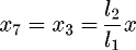
The differential lever mechanism is a type of amplification mechanism [16–18] composed of lever principle, which can overlay and amplify the displacement. Differential amplification can be divided into co-drive and reverse drive depending on the direction of input. Figure 1 shows the reverse drive principle. The input points are 1 and 4, input displacement is amplified by the lever 1-2-3 and 4-5-6. At points 6 and 7, get the displacement in the opposite direction (1)
(1)
 (2)
(2)
and the displacement difference between the two points is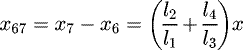 (3)
(3)
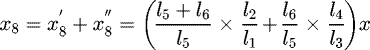
The second-stage lever 6-7-8 further amplifies the displacement difference X67. When point 6 is a fulcrum, the output of point 8 is equation (4). When point 7 is a fulcrum, the output of point 8 is equation (5). So the points 6 and 7 both move at the same time, point 8 is the superposition of two-point displacement, shows in equation (6).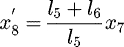 (4)
(4)
 (5)
(5)
 (6)
(6)
That is, the amplification ratio of differential displacement under reverse driving is
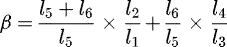 (7)
(7)
By the same reasoning, under the same direction driving in Figure 2, the amplification ratio of differential displacement is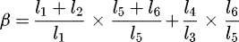 (8)
(8)
Therefore, the differential lever displacement amplification mechanism consists of two first-stage levers and two second-stage levers in series, and the final displacement output is obtained with overlay amplification.
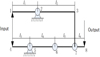 |
Fig. 1 Reverse drive principle. |
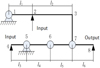 |
Fig. 2 The same direction drive. |
3 Design of displacement amplification mechanism
3.1 Flexure hinge design
Through the analysis of flexibility, accuracy and maximum stress of flexure hinge with different incision types, the single-axis bilateral straight circular flexure hinge has a high motion accuracy [19]. Therefore, in the amplification mechanism, all the flexure hinges adopt a straight circular flexure hinge, whose structure is shown in Figure 3. Where R is the cutting radius, b is the width, and t is the thickness of the flexure hinge.
Since the amplification mechanism is a planar mechanism (Tab. 1 is the main parameters of the amplification mechanism), the flexure hinge is mainly subject to the bending moment around the z-axis and axial tensile pressure along the x-axis. Therefore, it needs to calculate the bending stiffness and axial stiffness of the flexure hinge.
Under the action of torque Mz
, the bending stiffness of straight circular flexure hinge is calculated as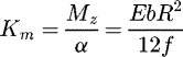 (9)where
 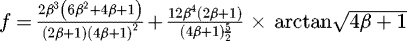 (β = R/t), E is the elastic modulus, α is the deflection angle of flexure hinge.
Under the action of axial force Fx
, the axial stiffness of the straight circular flexure hinge is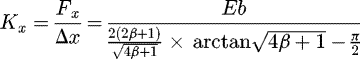 (10)where Δx is the displacement variation of flexure hinge in the X-direction.
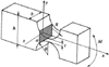 |
Fig. 3 The single-axis and double-side straight circular flexure hinge. |
Main parameters of the amplification mechanism.
3.2 Design of differential lever amplifying mechanism
The amplification mechanism is shown in Figure 4. To avoid the loss of transverse displacement and reduce the longitudinal coupling error, a type of symmetrical structure is adopted and fixed by two sets of symmetrical bolts. Using PZT to apply symmetrical load to the input end, and produce input displacement through the contraction or expansion on both sides. Then obtain the output displacement of the output end by the bending deformation of the flexure hinge.
Because the structure is symmetrical, takes half of the body for research. The composition of the semi-structure is shown in Figure 5.
Among them, points 1 and 5 are the input end of the mechanism, the displacement input is completed by PZT, and point 9 is the output platform. 4-5-6 and 2-1-3 simultaneously constitute the first-stage lever of the amplification mechanism, the displacement is transmitted to the second-stage lever 7-8-9 via pushrods P1 and P2. Through the superposition of two first-stage lever displacements and further amplification of second-stage lever displacements, a larger displacement magnification can be achieved with a large stroke. It is easily obtained that the geometric amplification of the mechanism is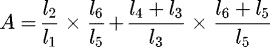 (11)according to the structural parameters in Table 1, A = 12.84.
Considering the force characteristics of the flexible mechanism, it is assumed that all deformation of the mechanism is caused by the deformation of the hinge. Because the hinges are not only bent but also axially stretched or compressed, there is a loss of displacement output throughout the mechanism. The actual input-output relationship is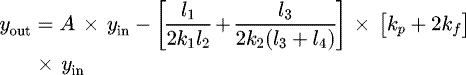 (12)where k1, k2 is the axial stiffness of push rods P1 and P2, respectively, kp
is the stiffness of PZT and kf
is the stiffness of the entire flexible mechanism, yin is the input displacement of the flexible mechanism. Considering that the stiffness of the PZT is not much greater than the stiffness of the flexible mechanism, the input displacement of the flexible mechanism is not equal to the elongation of the PZT. The relationship between the two is
(12)where k1, k2 is the axial stiffness of push rods P1 and P2, respectively, kp
is the stiffness of PZT and kf
is the stiffness of the entire flexible mechanism, yin is the input displacement of the flexible mechanism. Considering that the stiffness of the PZT is not much greater than the stiffness of the flexible mechanism, the input displacement of the flexible mechanism is not equal to the elongation of the PZT. The relationship between the two is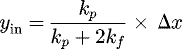 (13)where Δx is the elongation of PZT.
The stiffness of the flexible mechanism kf
can be derived from the energy principle. Specifically, the variable situation energy (input energy) of piezoelectric ceramics is equal to the elastic potential energy (output energy) of the flexible mechanism.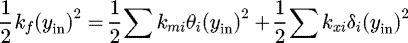 (14)where the first term at the right end of the equation is the sum of bending deformation energy of all flexure hinges, the second term is the sum of axial deformation energy of all flexure hinges, θi is the deflection angle of flexure hinges, and δi is the axial deformation of flexure hinges. Therefore, the final stiffness formula of the flexible mechanism is
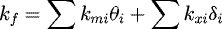 (15)
(15)
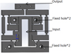 |
Fig. 4 Design sketch of a displacement amplification mechanism. |
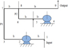 |
Fig. 5 Stress diagram of the differential lever amplification mechanism. |
3.3 Static analysis
The cutting center of the hinge in the flexible micro-displacement amplification mechanism is the dangerous section [20]. The maximum stress of the cutting center σ shall not exceed the allowable stress of the material [σ] during the design to meet the strength condition of the bending stress.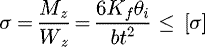 (16)where Wz is bending section modulus of the hinge cross-section to the z-axis.
After certain optimization of the flexure hinge parameters, the overall dimension of the structure is 97.1 mm × 98 mm × 10 mm. And it is guaranteed that when the input displacement is 50 µm, the maximum stress of the flexure hinge is not greater than the allowable stress of the material.
4 FEA and experimental verification
4.1 FEA
4.1.1 Static analysis
To verify the validity of the above theoretical model, it is necessary to carry out the finite element analysis of the differential lever displacement amplification mechanism. Under the premise that the model built is close to the real model, the result of finite element calculation can be considered as a relatively accurate result [21–23].
In ANSYS Workbench, according to the geometric model of a displacement amplification mechanism, Solid Works is used for modeling. The material is 60Si2Mn, its allowable stress is 785MPa, and its stress analysis and deformation are shown in Figures 6 and 7.
It can be seen from Figure 6 that the maximum stress occurs at the flexure hinge, and its value is 536.27MPa, which is less than the allowable stress of the material and meets the design requirements. At the same time, because the mechanism is designed symmetrically driven, the stress of the whole mechanism is symmetrically distributed, which is beneficial to the operation of the whole mechanism.
Figure 7 shows the deformation (displacement) analysis diagram of the amplification mechanism. In the process of simulation, when the input displacement of PZT is 50 µm, the output displacement of the amplification mechanism is 333.8 µm, and the amplification ratio is 6.68.
The maximum output displacement of the piezoelectric actuator is 50 µm. From the ANSYS analysis (Tab. 2), as the increase of input displacement, the output has a linear relationship with the input (Fig. 8). The maximum stress value of the mechanism also increases with the input displacement, and it will reach the maximum (σmax = 536.27 MPa < 785 MPa) when the input displacement is 50 µm, which meets the strength requirements.
In the case of no-load, the curves of input displacement-output displacement and input displacement-maximum stress are shown in Figure 8. The amplification ratio of the mechanism under different input is stable, and the linearity of output displacement and maximum stress is good.
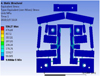 |
Fig. 6 Stress analysis diagram of the mechanism. |
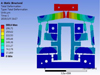 |
Fig. 7 Total deformation diagram of the mechanism. |
Amplification and strength under different input displacement.
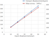 |
Fig. 8 The curves of input-output displacement and input displacement-maximum stress. |
4.1.2 Modal analysis
For the amplification mechanism, the natural frequency is an important index to evaluate the inherent characteristics, which is of great significance to system control and mechanism optimization design. Since the natural frequency is an important parameter in the design of a dynamic load structure, the modal analysis is performedby ANSYS Workbench, as shown in Figure 9.
Table 3 shows the natural frequencies of the first six modes of the amplification mechanism.
As can be seen from the sixth-order modal analysis, the natural frequency of mode 1 and mode 2 is 203.37 and 541.11 Hz respectively. and there are some overlaps at this time. In other modal analysis, it is found that the natural frequency of mode 4 is 930.58 Hz, which outputs the amplification displacement from the output end but also is the optimal driving frequency of the mechanism.
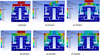 |
Fig. 9 The first six mode shapes of the mechanism. |
Natural frequency simulation results.
4.2 Experimental verification
The experimental platform is shown in Figure 10. The experimental device is mainly composed of inductance micrometer (TESATRONICTT80 from TESA, Inc.), PZT(SZBS 150/10/50vs15), and driving power(HPV series from Jiangsu Huibo Robot Technology Co., Ltd.). During the test, the amplification mechanism is fixed on the plane's precise positioning platform. The input displacement is generated by PZT, and the actual input and output displacement of the machine is measured by a displacement sensor.
When the input is 50 µm, compare the output displacement and amplification under different loads. The results are shown in Table 4, and the relationship between amplification and load is shown in Figure 11. The analysis results show that when a certain load is added at the output end, the displacement output is correspondingly reduced at the same time, instead of decreasing in a multiple relationships. As the load increases, the amplification of the mechanism becomes smaller and smaller, which will also affect the position change of the internal parts to touch, resulting in damage to the mechanism or no amplification effect. Therefore, the bearing capacity of the mechanism needs to be considered when adding the load.
Through the combination of PZT driving power supply and voltage driver, starts to increase the voltage by 10 until 120 V at a time, with a wait time of5s after each boot. When the voltage value reaches 120 V, wait for the creep speed of PZT to slow down, then depressurize, reduce the driving voltage of 10 V each time, and the waiting time is the same as 5 s. Repeat the experiment three times, and the results are shown in Figure 12.
Calculating the mean value of the above experiments and compare it with the displacement before amplification, and get Table 5.
Ignoring the displacement amplification at 0 V, it can be seen from Table 5 that the magnification is between 5.2 and 7.71 (Fig. 13), and its amplification ratio calculated with the mean value is A = 313.05/48.14 = 6.50.
The amplification ratio obtained through ANSYS simulation is 6.68, and that of the experiment is 6.50. The experimental results are consistent with the simulation, and the theoretical magnification ratio of the system is 12.84. This is due to the deformation of the lever arm of the multi-stage lever structure, which reduces the output displacement, while the lever arm is straight in the theoretical calculation. Besides, the number of flexure hinge points is relatively large, and the deformation of each flexure hinge needs to consume the output force of PZT, so they will cause ultimately loss of the whole output displacement.
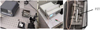 |
Fig. 10 Experimental platform. |
Output displacement and amplification under different loads.
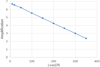 |
Fig. 11 Relationship between load and amplification. |
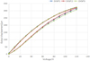 |
Fig. 12 Voltage and displacement diagram of the micro-displacement amplification mechanism. |
Voltage and displacement comparison of PZT before and after amplification.
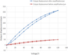 |
Fig. 13 Comparison of displacement output before and after amplification. |
5 Conclusion
To effectively improve the displacement output stroke of PZT and reduce the additional displacement, the paper proposes a type of symmetrical flexure hinge displacement amplification mechanism based on the differential lever. It expounds the working principle of the differential displacement amplification mechanism. According to structural symmetry, it establishes a semi-model of the micro-displacement amplification mechanism. Finally, the mechanism uses ANSYS software to carry out the finite element simulation analysis, and through experiments to verify its rationality.
By optimizing the parameters of the flexure hinge, it is guaranteed that the maximum stress is not greater than the allowable stress of the material when the input displacement is 50 µm. From the stress analysis diagram, we can see the maximum stress occurs at the flexure hinge of the amplification mechanism, and the maximum stress is 536.27 MPa < 785 MPa (allowable stress) to meet its strength requirements. The magnification ratio of ANSYS simulation and experiment is 6.68 and 6.50 respectively, which is consistent. Depending on the modal analysis, the best driving frequency occurs in the mode 4 (natural frequency is 930.58 Hz). The experimental results show that the maximum output displacement of the designed differential lever displacement amplification mechanism is 313.05 µm, and the amplification ratio can reach 6.50. The system adopts a type of symmetrical structure, so that the output additional displacement of the whole mechanism is smaller, which also provides a scientific basis for further improving the positioning accuracy of the micro/nano drive control system.
Acknowledgments
This research is supported by the “Quanzhou science and technology project” (project NO. 2018Z001), Natural Science Foundation of Fujian Province (NO. 2020J01086), National Natural Science Foundation of China (No. 51505161 and No. 61603144), and Subsidized Project for Postgraduates' Innovative Fund in Scientific Research of Huaqiao University (No. 18013080057).
References
- P.R. Ouyang, W.J. Zhang, M.M. Gupta et al., Overview of the development of a visual-based automated bio-micro-manipulation system, Mechatronics 17 , 578–588 (2007) [Google Scholar]
- G. Velasco-Herrera, Parallel micro-manipulator system with applications in micro-assembles and micro-machine-making, WSEAS Transactions on System 4 , 980–987 (2005) [Google Scholar]
- Y.M. Li, H. Tang, Q.S. XU et al., Development trend of micro-manipulation robot technology forbiomedical applications, Journal of Mechanical Engineering 47 , 1–13 (2011) [Google Scholar]
- N. Dechev, L. Ren, W. Liu et al., Development of a 6 degree of freedom robotic micro manipulatorfor use in 3D MEMS micro-assembly, IEEE International Conference on Robotics and Automation, ICRA, Orlando, 2006, pp. 281–288 [Google Scholar]
- L.Y. Zheng, J.Y. Shen, P.F. Wang et al., Research on flexure hinge amplification mechanism for piezoelectric actuator displacement amplification, Scientific and Technological Innovation and Application 24, 21–22 (2018) [Google Scholar]
- L.J. Lai, Z.N. Zhu, Design, modeling and testing of a novel flexure-based displacement amplification mechanism, Sensors and Actuators A: Physical 266 , 122–129 (2017) [Google Scholar]
- M. Li, X.F. Chen, Q. Lu, Simulation design of flexible mechanism of piezoelectric laminated actuation system, Mechanical design and manufacturing engineering 47 , 25–29 (2018) [Google Scholar]
- Q. Lu, W.Q. Huang, M.X. Sun, Parametric design of flexible amplification mechanism based on flexure hinge, Vibration, Test and Diagnosis 36 , 935–941 (2016) [Google Scholar]
- Q.S. Xu, Y.M. Li, Analytical modeling, optimization and testing of a compound bridge-type compliant displacement amplifier, Mechanism and Machine Theory 46, 183–200 (2011) [Google Scholar]
- G. Tang, P.J. ZOU, G.Y. Xie et al., Amplification mechanism of flexure hinge based on triangle and lever principle, Mechanical Design and Research 34 , 46–49 (2018) [Google Scholar]
- Z. Yang, T.L. Song, Design and analysis of flexible hinge amplification mechanism, Coal Mine Machinery 39 , 12–14 (2018) [Google Scholar]
- T. Liu, X.M. Zhang, Design of two-dimensional micro displacement platform based on flexure hinge lever amplification mechanism, Mechanical Engineer, 165–168 (2014) [Google Scholar]
- S.B. Choi et al., A magnification device for precision mechanisms featuring piezoactuators and flexure hinges: design and experimental validation, Mechanism and Machine Theory 42, 1184–1198 (2007) [Google Scholar]
- W. Dong, F.X. Chen, F.T. Gao et al., Development and analysis of a bridge-lever-type displacement amplifier based on hybrid flexure hinges, Precision Engineering 54 , 171–181 (2018) [Google Scholar]
- J.G. Wan, L.W. Zhong, Research and Analysis on the amplification ratio characteristics of bridge type micro-displacement amplifier, China Water Transport 18 , 117–119 (2018) [Google Scholar]
- J.J. Li, G.M. Chen, Optimal design of flexible two-stage differential micro-displacement amplification mechanism, Journal of Mechanical Engineering 55 , 21–28 (2019) [Google Scholar]
- K.J. Liu, Optimization design of lever type flexure hinge micro-displacement amplification mechanism. Chinese Society of Mechanics, Shanghai Jiaotong University, Chinese mechanical congress-2015 abstracts, 2015, p. 256 [Google Scholar]
- J.Y. Shen, H.J. Zhang, Y. Zhan, A calculation method of magnification of lever type flexure hinge mechanism with piezoelectric ceramic actuator, Journal of agricultural machinery 44 , 267–271 (2013) [Google Scholar]
- X. Wei, K. Tim, Flexure hinges for piezoactuator displacement amplifiers: flexibility, accuracy, and stress considerations, Precision Engineering 19 , 4–10 (1996) [Google Scholar]
- Y.M. Yu, J.S. Leng, Design and dynamic performance simulation of flexible micro displacement amplification mechanism, Mechanical Design and Research 27 , 48–51, 55 (2011) [Google Scholar]
- C.T. Wang, Y.Q. Wang, X.F. Yang et al., Analysis of stiffness characteristics of three kinds of four-bar flexure hinge mechanisms based on ANSYS, Mechanical Transmission 41 , 59–63, 76 (2017) [Google Scholar]
- X.Y. Jiang, D.F. Chen, Performance analysis of differential displacement amplifier based on ANSYS, Journal of Hubei University of Technology 25 , 77–79 (2010) [Google Scholar]
- G.M. Chen, Y.K. Ma, J.J. Li, A tensural displacement amplifier employing elliptic-arc flexurehinges, Sensors and Actuators A: Physical 247 , 307–315 (2016) [Google Scholar]
Cite this article as: W. Fan, H. Jin, Y. Fu, Y. Lin, A type of symmetrical differential lever displacement amplification mechanism, Mechanics & Industry 22, 5 (2021)
All Tables
All Figures
|
Fig. 1 Reverse drive principle. |
| In the text | |
|
Fig. 2 The same direction drive. |
| In the text | |
|
Fig. 3 The single-axis and double-side straight circular flexure hinge. |
| In the text | |
|
Fig. 4 Design sketch of a displacement amplification mechanism. |
| In the text | |
|
Fig. 5 Stress diagram of the differential lever amplification mechanism. |
| In the text | |
|
Fig. 6 Stress analysis diagram of the mechanism. |
| In the text | |
|
Fig. 7 Total deformation diagram of the mechanism. |
| In the text | |
|
Fig. 8 The curves of input-output displacement and input displacement-maximum stress. |
| In the text | |
|
Fig. 9 The first six mode shapes of the mechanism. |
| In the text | |
|
Fig. 10 Experimental platform. |
| In the text | |
|
Fig. 11 Relationship between load and amplification. |
| In the text | |
|
Fig. 12 Voltage and displacement diagram of the micro-displacement amplification mechanism. |
| In the text | |
|
Fig. 13 Comparison of displacement output before and after amplification. |
| In the text | |
Current usage metrics show cumulative count of Article Views (full-text article views including HTML views, PDF and ePub downloads, according to the available data) and Abstracts Views on Vision4Press platform.
Data correspond to usage on the plateform after 2015. The current usage metrics is available 48-96 hours after online publication and is updated daily on week days.
Initial download of the metrics may take a while.