| Issue |
Mechanics & Industry
Volume 25, 2024
|
|
|---|---|---|
| Article Number | 35 | |
| Number of page(s) | 11 | |
| DOI | https://doi.org/10.1051/meca/2024029 | |
| Published online | 20 December 2024 | |
Regular Article
Shipbuilding crane manipulator with closed-chain structure: structural design and kinematic performance analysis
1
College of Mechanical, Naval Architecture and Ocean Engineering, Beibu Gulf University, Qinzhou 535011, PR China
2
College of Mechanical & Electrical Engineering, Shaanxi University of Science and Technology, Xi'an, 710021, PR China
3
Jiangxi Institute of Mechanical Science, Nanchang 330095, PR China
* e-mail: This email address is being protected from spambots. You need JavaScript enabled to view it.
Received:
8
February
2023
Accepted:
24
June
2024
Abstract
Traditional shipbuilding crane manipulator is widely used in the process of block lifting and erection of ships, but there are generally problems, such as inflexible output trajectory, limited workspace and low working efficiency. In order to solve above problems, a novel hybrid shipbuilding crane manipulator with closed-chain structure and weakly-coupled characteristics based on multi-DOF (Degree-of-Freedom) mechanism is proposed. Then, a systematically structural and kinematic modeling and analysis method is presented to describe the coupling degree, singular configurations, workspace, motion trajectory, dexterity capacity and static stiffness performances of this type of closed-chain structure mechanism. Results of the numerical examples verify the correctness, accuracy and efficiency of the proposed method. Meanwhile, compared with the traditional shipbuilding crane manipulator, the proposed novel manipulator can finish lifting and transportation operation more efficient, which can also be applied in fields such as: innovative design of oil and gas drilling platforms, deck machinery, construction machinery and other engineering equipment.
Key words: Shipbuilding crane manipulator / POC set / singularity / workspace / performance analysis / motion trajectory
© Y. Pan et al., Published by EDP Sciences 2024
 This is an Open Access article distributed under the terms of the Creative Commons Attribution License (https://creativecommons.org/licenses/by/4.0), which permits unrestricted use, distribution, and reproduction in any medium, provided the original work is properly cited.
1 Introduction
Shipbuilding industry is a comprehensive industry that provides strategic technical and equipment support for maritime transportation, marine development, etc., and plays an important role in the development of key industries, such as equipment manufacturing and electronic information. Shipbuilding cranes take an important links in the ship repair and construction process, which accounts for about 45% of the total ship construction workload [1].
Shipbuilding cranes can be divided into portal cranes and gantry cranes. At present only single freedom cranes are using in shipbuilding. Those traditional cranes as shown in Figure 1 [2] (schematic diagram as shown in Fig. 3a) are difficult to output flexible working trajectory because these single DOF could only output fixed trajectory, and also exist high production cost, high assembly process requirements, difficult maintenance, etc.
At present, the research on shipbuilding and port cranes mainly focuses on power systems, evaluation methods, structural optimization, reliability, etc. For example, Hakan et al. [3] studied an intelligent tandem hybrid control method for gantry cranes. Zhao et al. [4] introduced the energy storage system of a port crane hybrid power system. Yong et al. [5] analyzed the non-circulation reversible speed regulation system of port crane. Qian et al. [6] proposed a port crane fault diagnosis method based on genetic algorithm to optimize BP (Back Propagation) neural network. Andrej et al. [7] presents a method for determination of dynamic reaction forces in knuckle boom cranes. Lee et al. [8] studied the control of a gantry and a floating crane was performed for the block erection operation, which proved that reliable control was achieved under various environmental conditions. Wang [9] provided a function-oriented quality control method for shipbuilding. As we can see that the design of new mechanism of shipbuilding crane is very rare.
In the 1990s, Jones first proposed the concept of hybrid manipulator with multi-DOF [10]. After decades of development, most of the current hybrid manipulators' main bodies are mainly parallel mechanisms, supplemented by end-series manipulators. Hybrid manipulator combines the advantages of series and parallel mechanisms [11], has the advantages of large workspace, strong stiffness, high load-capacity, high precision, etc., which attracting extensive attention and research from many scholars and experts. Such as: Dong et al. [12] introduced a dynamic modeling and design method of a novel type of 5-DOF hybrid robot for machining that considers the three performance indicators of workspace/machine volume ratio, lateral stiffness, and low-order mode. Saminathan et al. [13] designed a new module with 2-DOF by connecting two and three modules in series, a hybrid manipulator with 4 and 6-DOF can be formed respectively. Arora et al. [14] proposed a three-dimensional hybrid manipulator, which connected two parallel manipulators in series. Hu et al. [15] used Grassmann-Cayley algebra to propose a method for deriving terminal constraints of 5-DOF hybrid manipulator, and solved terminal-DOF characteristics. Sun et al. [16] presented a hybrid human-like manipulator with 8-DOF, and gave a general method to solve the inverse displacement problem of the hybrid mechanism. These may provide good references for the innovative design of novel shipbuilding crane manipulators.
However, the problems of traditional shipbuilding cranes have not been solved, which is one of the important reasons restricting the development of shipbuilding crane. In order to improve the trajectory of traditional single-DOF crane, the rest of the paper is organized as follows. Firstly, a hybrid shipbuilding crane manipulator is proposed. Then, the structure is described and analyzed as well as its coupling degree, position, singularities, workspace and motion trajectory. Next, the dexterity capacity and static stiffness performances are investigated. Finally, the lifting simulation are investigated to confirm the feasibility of the design.
 |
Fig. 1 Currently used crane manipulator. |
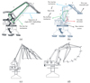 |
Fig. 2 Shipbuilding crane manipulator. (a) Single-DOF shipbuilding crane manipulator; (b) Hybrid shipbuilding crane manipulator; (c) Trajectory of single-DOF shipbuilding crane manipulator; (d) One Trajectory of Hybrid shipbuilding crane manipulator. |
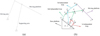 |
Fig. 3 Schematic diagram (a) tradition shipbuilding crane manipulator (b) Hybrid shipbuilding crane manipulator. |
2 Configuration
This work introduces a novel category of shipbuilding crane manipulators with multi-DOF, weakly-coupled characteristics, hybrid structures, as shown in Figure 2 [17]. According to the process requirements of shipbuilding, a 9-bar and 11-pair planar 2-DOF mechanism is obtained through configuration evolution, and taken as an example for analysis and research, as depicted in Figure 1b, and the configuration can be described as: (1) Main body: composed of two planar four-bar branch chains with a two-link sub-chain. With the joint movements of the two chains, the main body can achieve 2T output trajectories in the plane. (2) Wire rope retractable part: realize the retractable action of the wire rope. (3) Base rotation section: the waist rotation of shipbuilding crane manipulator can be achieved.
With the cooperation of the main body, wire rope retractable and base rotation parts, the proposed shipbuilding crane manipulator can accomplish given spatial 4-DOF lifting tasks. By comparing Figure 2c and 2d, we can obtain the differences between the two mechanisms, as depicted in Table 1.
Comparison of shipbuilding crane manipulators.
2.1 DOF analysis
Introduce the position and orientation characteristics(POC) set theory [18], and analyze the DOF of the shipbuilding crane structure, as shown in Figure 3.
According to Yang [19], a formula for calculating DOF without loss of generality is proposed as:
 (1)
(1)
where, F- DOF of mechanism; fi- DOF of the ith joints; m − the number of joints; υ- independent loop (υ = m − n + 1, n- the number of link); - the number of independent loop equations; dim. {} is the dimension of the POC set; Mbi-the POC sets of the ith branch; Mb(j+1) − the POC sets of the (j+1)
th
branch's end component.
- the number of independent loop equations; dim. {} is the dimension of the POC set; Mbi-the POC sets of the ith branch; Mb(j+1) − the POC sets of the (j+1)
th
branch's end component.
Combined with equation (1), the DOF is analyzed as follows:
The 1st independent loop can be written as:
 (2)
(2)
 (3)
(3)
where, t2(⊥ R3)indicates there is two translation along a direction, which is perpendicular to the R3 pair axis, r1(||R3) indicates there is one rotation parallel to the R3 axis; t1(⊥ R4)indicates there is one translation perpendicular to the R4 pair axis ; r1(||R8) indicates there is one rotation parallel to the R8 axis; indicates that there is one translation the associated translation of the Ri pair; r1(||R3) indicates there is one rotation parallel to the R3 axis.
The 2nd independent loop can be expressed as:
 (4)
(4)
 (5)
(5)
where, t2(⊥ R8)indicates there is two translation perpendicular to the R3 pair axis.
The 3rd independent loop can be described as:
 (6)
(6)
Where, t2(⊥ R10)indicates there is two translation perpendicular to the R10 pair axis; r1(||R10) indicates there is one rotation parallel to the R10 axis.
Substitute the above equations into equation (1), yields:
 (7)
(7)
It can be calculated from the above formulas that shipbuilding crane structure has two-DOF and two-dimensional motion on the plane. Results show that novel shipbuilding crane manipulator can meet the requirements of various lifting conditions in ship construction and has more flexible trajectory output [20].
2.2 Analysis of coupling degree
In the hybrid shipbuilding crane structure, the coupling degree of the mechanism reflects the geometric characteristics, topological structure and the difficulty of solving kinematics and dynamics of the end-effector like the elephant trunk girder. On the basis of the POC set theory [21], then we have:
 (8)
(8)
where, Δj is the constraint degree of the jth single opened chains SOC; m is the number of joints contained in the SOC; Ij is the number of actuated joints in the jth SOC; fi, is the same definition as in equation. (1).
From the definition of coupling degree, we can get, yields:
 (9)
(9)
Then we have:
 (10)
(10)
Substituting equation (10) into (9), yields:
 (11)
(11)
In summary, the coupling degree κ is 0. Therefore, the lifting manipulator is weakly-coupled mechanism. Compared with the high coupling mechanism, when solving the kinematics and dynamics, there is no need to solve multiple loop-equations simultaneously, and only need to be solved separately. In the following researches, such as workspace, singularity, carrying capacity and stiffness performance, the mathematical analytical expression of the relationship between output parameters and input parameters can be obtained for the weakly-coupled manipulator, which is conducive to the subsequent scale optimization, error analysis and dynamic analysis. At the same time, the weakly-coupled manipulator is beneficial to improve the kinematic, static stiffness, dynamic performance and real-time control of the mechanism, which has a good application prospect.
3 Kinematics analysis
On the basis of the coordinate system and the vector relationship as depicted in Figure 4, the kinematic analysis of the mechanism can be carried out as follows:
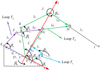 |
Fig. 4 Schematic diagram of hybrid shipbuilding crane. |
3.1 The four-bar (Loop T1) mechanism
The vector relation of the four-bar mechanism is written as:
 (12)
(12)
Then we can get:
 (13)
(13)
The position of point G can be obtained as:
 (14)
(14)
3.2 The four-bar (Loop T2) mechanism
Similarly, the position of point H is calculated by:
 (15)
(15)
3.3 The six-bar (Loop T3) mechanism
In the same way, the position of point I can be computed as:
 (16)
(16)
The position relationship between the two active arms of the shipbuilding crane and the end point of the elephant nose beam I is shown in Table 2.
The input parameters of the two active arms of shipbuilding crane and the output parameters at the end point of the elephant nose beam.
3.4 Inverse position
According to the reverse of the forward solution of the position, reverse the posture of Loop T1, Loop T2 and the trunk of the elephant, yields:
 (17)
(17)
 (18)
(18)
 (19)
(19)
The position relationship between the nose beam end point I and the two active arms of the shipbuilding crane is shown in Table 3.
By comparing Tables 2 and 3, we can see that the forward and inverse solution values of shipbuilding lifting mechanism are basically equal, indicating that the mathematical model of the forward and inverse solution of shipbuilding lifting mechanism is correct.
The input parameters at the end point of the nose beam of the shipbuilding crane and the output parameters of the two driving arms.
3.5 Velocity Jacobian matrix
The constraint equations of mechanism can be written as:
 (20)
(20)
 (21)
(21)
 (22)
(22)
Then the forward and inverse velocity Jacobian can be obtained:
 (23)
(23)
where:


3.6 Singularity and workspace analysis and simulation
The position of point C can be computed as:
 (24)
(24)
Then
 (25)
(25)
when det(J3) = 0, the mechanism has singular configurations, where β2 = β1 or β2 = β1 + π.
similarly, we can get, yields:
 (26)
(26)
when det(J4) = 0, the mechanism has singular configurations, where β8 = β5 or β8 = β5 + π.
In the same way, we have:
 (27)
(27)
when det(J5) = 0, the mechanism has singular configurations, where β4 = β9, β4 = β9 + π or β10 = β8, β10 = β8 + π
Meanwhile, if the rod DKJI is regarded as a single-open chain mechanism, the singular configurations exist, where β10 = β9 or β10 = β9 + π. Some singular configurations are depicted in Figure 5.
In accordance with the relationship between the lengths of the four-bar mechanism and five-bar mechanism in Grashof criterion [22,23], a set of mechanism dimension parameters as shown in Table 4 are given in combination with the transmission angle and pressure angle of the mechanism when typical shipbuilding crane lifting operations are required.
Combined with the forward mathematical model and considering the singularities, the mathematical model and constraints were imported into the software, and the cloud images of the mechanism in the theoretical three-dimensional workspace and plane workspace were obtained, as depicted in Figure 6.
Figures 6a and 6b are the theoretical three-dimensional and plane workspace diagrams respectively. From Figure 6b, it can be seen that the lifting mechanism has a larger workspace, and its transverse theoretical working range is 2.0m ∼12.1m and vertical theoretical working range is 0.48m ∼21.8m. Figures 6c and 6d are the actual three-dimensional and plane workspace diagrams in combination with actual lifting conditions respectively. It can be seen from Figures 6c and 6d that the actual reachable space range is relatively wide. Its horizontal theoretical working range is 8.3m ∼9.9m and vertical theoretical working range is 0.87m ∼13.7m.
Through the simulation analysis of the shipbuilding crane manipulator, a variety of lifting working trajectories that meet the actual lifting operating conditions can be obtained, as depicted in Figure 7. Figure 7a is the simulation trajectory of the traditional single-DOF crane manipulator, and Figure 7b is the trajectory diagram of novel hybrid shipbuilding crane manipulator completing a lifting task in a single-plane. The rest of the trajectory simulation diagram is a hybrid shipbuilding crane manipulator, which is a simulation trajectory obtained by combining the rotating platform and changing the input parameter values of the two active rods for different hoisting and lifting operating conditions.
It can be seen that compared with the traditional single-DOF crane manipulator as show in Figure 7a, the hybrid shipbuilding crane structure can not only complete a single-action, but also realize flexible output trajectories as show in Figure 7b, the end-effector can reach the nearest point and the far point when hybrid shipbuilding crane in the different posture as show in Figures 7c and 7d, which can adapt to the requirements of lifting and unloading operations under a variety of different working conditions, and meets the task requirements of the existing shipbuilding cranes.
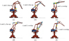 |
Fig. 5 Partial singular configurations. |
Dimensional parameters.
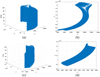 |
Fig. 6 Workspace. (a) Theoretical three-dimensional workspace, (b) Theoretical plane workspace, (c) Actual three-dimensional workspace, (d) Actual plane workspace. |
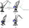 |
Fig. 7 Variety of actual lifting operation trajectories. |
4 Performance analysis
4.1 Dexterity analysis
It is necessary to consider the operation requirements under various conditions, which requires the structure to respond quickly. In general, the dexterity index is used to reflect the movement performance of the crane structure, which indicates the ability to obtain the target and the flexibility of each bar of the manipulator.
By using spectral norm to calculate the condition number of Jacobian matrix,
 (28)
(28)
The spectral norm method of matrix is used to solve the above norm.
Then:
 (29)
(29)
where, λmax is the Maximum eigenvalue ; σmax is the Maximum singular value.
From the definition in equation (29), equation (28) can be rewritten as follows.
 (30)
(30)
Then we can find that 1≤ L(k) ≤ + ∞,which is not intuitive to reveal the dexterity. To further describe the dexterity of shipbuilding cranes manipulator:
 (31)
(31)
By given the 80 ≤ β1 ≤ 100, 120 ≤ β4 ≤ 130 the dexterity changes with variations of beta1, beta4 and x,y:
Figures 8a and 8b shows that the dexterity of the shipbuilding cranes is low at the beginning of operation. As the input angle of the two active arms gradually increases, the dexterity index is mostly concentrated between 0.05 and 0.25, and the maximum value can reach 0.3. During the operation of the lifting mechanism, its overall dexterity index is far from 0 (far from singular position), which meets the operation requirements of low-speed heavy-load shipbuilding cranes.
 |
Fig. 8 The dexterity changes with variations of beta1, beta4 and x,y. |
4.2 Static stiffness analysis
The trunk of the elephant begins to lift the components, the reaction force exerted by the components does virtual work, which is equal to the deformation energy generated by each rod, and the relationship is [24]:
 (32)
(32)
where, F represents the force on the bridge of the elephant trunk girder; ΔX represents the slight displacement of the bridge of the elephant trunk girder; ψ represents the generalized external force received by the end of each rod; Δγ represents the generalized displacement caused by the generalized force acting on the end of each rod.
Then, the stiffness matrix of the shipbuilding crane structure can be written as:
 (33)
(33)
where, k = diag[k11,…, knn] is the joint stiffness matrix of the shipbuilding crane.
Generally, the rigid component is taken as knn= 1. Then the stiffness cloud diagram of the hybrid crane structure is as shown in Figure 9.
It can be seen from Figure 9 that the overall rigidity of the shipbuilding crane structure is still relatively in line with the requirements of lifting operations. When the initial parameters of the two active booms are input, the rigidity value of the crane structure can reach 1017. When the angle of the active boom 1 is at 80° ∼90°, its stiffness value shows a slow upward trend. At 90° ∼100°, the stiffness value rises proportion significantly. At this time, the crane structure is in the lifting state, and the stiffness of the rods is required to be at the best status, as can be seen from the cloud diagram, the design of the crane basically meets the operational requirements of shipbuilding cranes.
 |
Fig. 9 Cloud diagram of posture and position stiffness performance. |
5 Conclusion
In order to solve the problems of traditional single-DOF crane with fixed and poor trajectory, limited working space and low working efficiency, this paper designs a new type of two-DOF hybrid drive weak coupling mechanism based on closed-loop mechanism. By Using POC set theory, the DOF of the manipulator was analyzed, and coupling degree was calculated. Then, the closed-loop vector method and constraint equations were used to develop a mathematical analytical model of mechanism kinematics, and the kinematics characteristics of position and velocity when completing a given lifting task were carried out. Based on velocity Jacobian matrix, the singular configurations were solved, the dexterity capacity and static stiffness performances were analyzed. Combined with singular configurations, theoretical workspace range and actual workspace combined with actual lifting conditions were obtained. Through trajectory comparison, it could be seen that hybrid crane manipulator combined with rotating platform could output trajectory that met different operation requirements, and the trajectory was flexibility. Results show that the hybrid crane manipulator with closed-chain structure and weakly-coupled characteristics compared with the traditional crane can achieve faster response speed, larger working space, more flexible trajectory, can be used in the lifting operation of ship construction, which provides a novel configuration for the field of shipbuilding lifting machinery and may also provide reference for the innovative design and application of other construction machinery.
Funding
This research was funded by [Guangxi Natural Science Foundation] grant number [2023JJB110039].
Conflicts of interest
All authors disclosed no relevant relationships.
Data availability statement
The data that support the findings of this study are available from the corresponding author upon reasonable request.
Author contribution statement
All authors were involved in the design of the model and discussion of the results. Conceptualization Yuchen Pan; writing original draft preparation Minghang Yue and Zhining Deng; validation, review Yuchen Pan; supervision Zhanbin Meng and Yufu Li. All authors have read and agreed to the published version of the manuscript.
References
- L. Bai, Research on the Automated Design Method for Ship Block Lifting, Master Dissertation, Dalian University of Technology, Liaoning, 2013 [Google Scholar]
- W. Haobai, Research on the influence of luffing radius on stress of combinatorial boom portal slewing crane on detected data analysis, IOP Conference Series: Earth and Environmental Science, 769, 1–5 2021 [Google Scholar]
- Y. Hakan, B. Serkan, An intelligent serial connected hybrid control method for gantry cranes, Mech. Syst. Signal Process. 146, 107011 (2020) [Google Scholar]
- N. Zhao, N. Schofield, W.Q. Niu, Energy storage system for a port crane hybrid power-train, IEEE Trans. Transp. Electr. 2:4, 1–1 (2016) [Google Scholar]
- X.U. Yong, X. Gong, Z.H. Zhang, Z.F. Qiao, Systematic research on non-circulation reversible speed regulation system of port crane based on MATLAB, J. Zhejiang Inst. Commun. 20, 34–37 (2019) [Google Scholar]
- Z. Qian, Optimizing BP neural network based on genetic algorithm for fault diagnosis of port crane, Mach. Build. Autom. 48, 172–175 (2019) [Google Scholar]
- C. Andrej, E. Olav, Dynamic modelling and force analysis of a knuckle boom crane using screw theory, Mech. Mach. Theory, 133, 179–194 (2018) [Google Scholar]
- H. Lee, M. Roh, S. Ham, Underactuated crane control for the automation of block erection in shipbuilding, Autom. Constr. 124, 103573, (2021) [CrossRef] [Google Scholar]
- H. Wang, Y. Guo, X.F. Liang, H. Yi, A function-oriented quality control method for shipbuilding, Ships Offshore Struct. 14:2, 220–228 (2019) [CrossRef] [Google Scholar]
- L.C. Tokuz, J.R. Jones, Power transmission and flow in the hybrid machines, The 6th International Machine Design and Production Conference, MENU, Ankara, Turkey, 1994, pp. 209–218 [Google Scholar]
- Y.J. Pi, X.Y. Wang, X. Gu, Synchronous tracking control of 6-DOF hydraulic parallel manipulator using cascade control method, J. Cent. South Univ. Technol. 18, 1554–1562 (2011) [CrossRef] [Google Scholar]
- C. Dong, H. Liu, J. Xiao, H. Tian, Dynamic modeling and design of a 5-DOF hybrid robot for machining, Mech. Mach. Theory, 165, 104438 (2021) [CrossRef] [Google Scholar]
- R.V. Saminathan, Topology design and position analysis of a reconfigurable modular hybrid-parallel manipulator, Proc. International Design Engineering Technical Conferences and Computers and Information in Engineering Conference, Anaheim, CA, 2019 [Google Scholar]
- R. Arora, T.K. Bera, Impedance control of three dimensional hybrid manipulator, J. Mech. Sci. Technol. 34, 359–367 (2020) [CrossRef] [Google Scholar]
- B Hu, Y. Shi, L. Xu, P. Bai, Reconsideration of terminal constraint/mobility and kinematics of 5-DOF hybrid manipulators formed by one 2R1T PM and one RR SM, Mech. Mach. Theory, 149, 103837 (2020) [Google Scholar]
- P. Sun, Y.B. Li, Z.S. Wang, K. Chen, Y. Yue, Inverse displacement analysis of a novel hybrid humanoid robotic arm, Mech. Mach. Theory, 147, 103743 (2020) [CrossRef] [Google Scholar]
- H.Z. Luo, Optimization design for luffing mechanism of portal slewing crane, Appl. Mech. Mater. 3282, 577–577 (2014) [Google Scholar]
- X. Zhu, H. Shen, C. Wu, D. Chablat, T. Yang, Computer-aided mobility analysis of parallel mechanisms, Mech. Mach. Theory, 148, 103810 (2020) [CrossRef] [Google Scholar]
- T.L. Yang, Topology Structure of Robot Mechanism, 1st ed. China Machine Press, Beijing, 2004 [Google Scholar]
- Z.N. Deng, Y.C. Pan, M.H. Yue, Z.B. Meng, A novel multi-dof shipbuilding crane manipulator: type synthesis and structure analysis, Adv. Mech. Des. 111, 1123–1136 (2022) [Google Scholar]
- H.P. Shen, Y.N. Zhao, J. Li, L.A., G.L.Wu, D. Chablat, A novel partially-decoupled translational parallel manipulator with symbolic kinematics, singularity identification and workspace determination, Mech. Mach. Theory, 164, 104388 (2021) [CrossRef] [Google Scholar]
- S.B. Nokleby, R.P. Podhorodeski, Optimization-based synthesis of grashof geared five-bar mechanisms, J. Mech. Des. 123:4, 529–534 (2001) [CrossRef] [Google Scholar]
- W.T. Chang, C.C. Lin, L.I. Wu, A note on grashof's theorem, J. Marine Sci. Technol. 13, 239–248 (2005) [Google Scholar]
- Y.Z. Ni, Optimal Design of Static Stiffness of 3UPS-RPR Parallel Mechanism, Master Dissertation, Tiangong University, Tianjin, 2017 [Google Scholar]
Cite this article as: Y. Pan, M. Yue, Z. Meng, Y. Li, Shipbuilding crane manipulator with closed-chain structure: structural design and kinematic performance analysis, 25, 35 (2024)
All Tables
The input parameters of the two active arms of shipbuilding crane and the output parameters at the end point of the elephant nose beam.
The input parameters at the end point of the nose beam of the shipbuilding crane and the output parameters of the two driving arms.
All Figures
|
Fig. 1 Currently used crane manipulator. |
| In the text | |
|
Fig. 2 Shipbuilding crane manipulator. (a) Single-DOF shipbuilding crane manipulator; (b) Hybrid shipbuilding crane manipulator; (c) Trajectory of single-DOF shipbuilding crane manipulator; (d) One Trajectory of Hybrid shipbuilding crane manipulator. |
| In the text | |
|
Fig. 3 Schematic diagram (a) tradition shipbuilding crane manipulator (b) Hybrid shipbuilding crane manipulator. |
| In the text | |
|
Fig. 4 Schematic diagram of hybrid shipbuilding crane. |
| In the text | |
|
Fig. 5 Partial singular configurations. |
| In the text | |
|
Fig. 6 Workspace. (a) Theoretical three-dimensional workspace, (b) Theoretical plane workspace, (c) Actual three-dimensional workspace, (d) Actual plane workspace. |
| In the text | |
|
Fig. 7 Variety of actual lifting operation trajectories. |
| In the text | |
|
Fig. 8 The dexterity changes with variations of beta1, beta4 and x,y. |
| In the text | |
|
Fig. 9 Cloud diagram of posture and position stiffness performance. |
| In the text | |
Current usage metrics show cumulative count of Article Views (full-text article views including HTML views, PDF and ePub downloads, according to the available data) and Abstracts Views on Vision4Press platform.
Data correspond to usage on the plateform after 2015. The current usage metrics is available 48-96 hours after online publication and is updated daily on week days.
Initial download of the metrics may take a while.