| Issue |
Mechanics & Industry
Volume 25, 2024
|
|
|---|---|---|
| Article Number | 34 | |
| Number of page(s) | 14 | |
| DOI | https://doi.org/10.1051/meca/2024033 | |
| Published online | 18 December 2024 | |
Original Article
Design and experimental verification of the picking cam mechanism for safflower filaments
1
School of Mechatronic Engineering, Xi’an Technological University, Xi’an 710021, China
2
School of Mechatronic Engineering, Xinjiang Institute of Technology, Aksu 843000, China
* e-mail: This email address is being protected from spambots. You need JavaScript enabled to view it.
Received:
25
April
2024
Accepted:
17
November
2024
Abstract
A picking head for automated harvesting of safflower filaments is designed to address the low manual harvesting efficiency and scarce automatic harvesting machinery. Based on the cluster growth characteristics of safflower filaments and the requirements for filament harvesting, the key structures and parameter ranges of the “∞”-shaped cam and cutting tools are established. Using ANSYS/LS-DYNA simulation analysis, the effects of the blade edge angle, cutting inclination, and cutting speed on the mechanical properties during filament cutting are explored. After that, a safflower filament picking head cutting test bench is built. Using the Central Composite Design method, a regression model between different test factors and indicators is established, and the response surface analysis and parameter optimization are performed for the interacting factors. The optimal parameters are a cam rotational speed of 32.6 r/min, a blade edge angle of 22.5°, and a cutting inclination of 19.6°. Five repeated bench tests are conducted using these parameters for verification. The experiments show that the average success rate of cutting filaments is 90.5%, and the error between the experimental and theoretical optimal values does not exceed 2.5%. The optimization model is reasonable and feasible, meeting the design requirements of the cutting of the safflower filament picking head. The results can provide a reference for the design and development of automated safflower harvesting devices.
Key words: Safflower filaments / cam / picking head / cutting / design experiment
© B. Chen et al. Published by EDP Sciences 2024
 This is an Open Access article distributed under the terms of the Creative Commons Attribution License (https://creativecommons.org/licenses/by/4.0), which permits unrestricted use, distribution, and reproduction in any medium, provided the original work is properly cited.
1 Introduction
Safflower (Carthamus tinctorius L.), also known as grass safflower or thistle safflower, can promote blood circulation, eliminate blood stasis, regulate menstruation, and relieve pain [1]. It is an important source of dyes and safflower seeds are rich in unsaturated fatty acids. It is also an economic crop that integrates medicinal materials, dyes, oil and feed [2,3]. Originated from the “Crescent Zone” along the Mediterranean coast [4,5], safflower is suitable for the environments with dry climates, strong cold resistance, poor soil tolerance, and sufficient light. Due to its unique geographical environment, Xinjiang has become the main base for safflower cultivation in China, accounting for more than 80% of the national total output [6,7]. With the continuous increase in market demand for safflower, safflower market is accelerating its development towards industrialization and commercialization. However, in the entire safflower industry chain, the harvesting of safflower filaments has not yet been mechanized. Manual harvesting is labor-intensive and inefficient, resulting in delayed harvesting and significant waste [8–10].
To solve the mechanization problem of safflower filament harvesting, extensive studies on mechanical, pneumatic, and intelligent harvesting technologies were conducted. Siavash et al. designed a safflower filament harvester based on a suction-cutting mechanism [11]. Although this device demonstrated some promise in laboratory trials, its radial fan blade and filament storage compartment were suboptimally configured, leading to significant filament loss. An Italian team developed a safflower filament-picking robotic arm utilizing vacuum-grasping technology [12]. This device identifies target flowers through image-based filament feature analysis and uses a pneumatic system to swiftly collect the filaments, showing notable precision in recognition and collection. Ehlert et al. proposed a comb-tooth picking mechanism chamomile [13], a plant with similar growth morphology to safflower. This device uses 12 movable and fixed comb teeth to pull chamomile from the plant and transport it to a collection box through an air duct. Ge et al. designed a dual-roller structure for safflower filament collection [14,15], which requires workers to manually align the device with the filaments while bearing the equipment's weight, resulting in a huge labor burden. Based on manual filament-picking actions, Zhang et al. developed a three-finger pulling end-effector incorporating a clamping mechanism, motor, and finger components [16]. However, there are instability issues in practical applications. Cao et al. developed a mechanical safflower filament harvester capable of large-scale blind harvesting [17]. However, its picking mechanism inflicts considerable damage on the safflower plants, flowers, and filaments, necessitating further structural optimization. Zhang et al. designed a hand-held safflower filament picker based on the shearing principle using a point-to-point picking approach [18]. Hui et al. invented a parallel safflower-picking robot with an end-effector that uses a crank-slider mechanism to cut filaments [19–21]. However, the large end-effector size often interferes with safflower corm positioning, resulting in low picking efficiency. Wang et al. proposed an intelligent filament-picking method based on machine vision algorithms [22]. Currently, most safflower harvesting devices mainly rely on manual assistance, with low automation levels and high operational intensity. Due to inadequate design of end effectors, some automated picking devices face high rates of omission and damage. To advance safflower filament harvesting technology, it is necessary to design a compact, swift, and highly adaptable end-effector to improve picking efficiency and minimize damage rates.
Existing safflower filaments picking heads generally have the disadvantages of large size, low picking efficiency, severe damage to the filaments, and difficulty in matching with intelligent robotic arms. To address these issues, based on the clustered growth characteristics and harvesting requirements of safflower filaments, an end-effector picking head that mimics the safflower growth morphology and responds swiftly is designed. This design aims to achieve a compact and lightweight structure while effectively adapting to the motion control of intelligent picking robot arms. Starting with an analysis of the harvesting requirements and growth material characteristics of safflower, the overall plan and structural layout of the picking head are determined. The key components of the picking head-the cam mechanism and cutter are focused. Through theoretical analysis and software simulation, the structural form and parameter range of the core components are clarified, and the influence of different factors on the effectiveness of filament cutting is evaluated. Finally, bench tests are conducted to further verify the optimal working parameters for the end-effector picking head in actual safflower filament harvesting.
2 Materials and methods
2.1 Safflower harvesting requirements and material characteristics
The requirements and material characteristics for safflower harvesting are the main bases for designing the end-effector picking head [23,24]. The safflower variety selected in this experiment is the Xinjiang “Yumin Thornless Safflower” series planted at the Labor Education Practice Base of Xinjiang University of Technology.
2.1.1 Safflower harvesting requirements
The growth of safflower filaments has clustering characteristics and morphological changes during blooming. The optimal harvesting time is when the filament color changes from yellow to orange-red, which is between the second and third day after flowering [9,10]. At this time, the filaments form an umbrella shape above the flower fruit, as shown in Figure 1a, which can be separated from the flower fruit using a cutter with a small corolla diameter. Considering that each flower fruit will bloom continuously for two to three cycles throughout its life, the harvesting technique must ensure that the flower fruit is not damaged and harvested in a timely manner. Damage to the flower fruit may cause it stopping flowering and affecting seed quality. If the filaments are not harvested in time, they will gradually wither due to a decrease in water content and adhere to the flower fruit, becoming semi-dry or dry filaments.
Consequently, the number of blooming cycles of the flower fruit is also reduced to one, seriously affecting the yield and economic benefits of filaments. Therefore, when designing mechanized harvesting devices, it is necessary to meet these detailed harvesting requirements to ensure effective integration of agricultural machinery and cultivation techniques.
 |
Fig. 1 Measurement of characteristic parameters of safflower materials. |
2.1.2 Measurement of safflower material characteristic parameters
During the automated harvesting of safflower filaments, to avoid positioning deviations, serious damage to filaments and fruit balls caused by improper picking head, or inability of the effective cutting, the biological material characteristics of safflower are measured and analyzed, as shown in Figure 1. It mainly includes morphological growth characteristics and mechanical properties. The growth morphology parameters were measured with a Vernier caliper with an accuracy of 0.02 mm, while the mechanical properties were measured using a MED-01 type mechanical property tester with an experimental accuracy of ±0.5%. To measure the mechanical properties, a self-designed shearing device was placed between the upper and lower fixtures, and a compression test was conducted to automatically record the force when the blade cut the safflower filaments, as shown in in Figure 1b. This measurement adopts the five-point method of the agricultural machinery testing conditions to obtain field samples. 30 safflowers were selected on the third day of blooming (i.e., the optimal harvesting period) at each sampling point, and completed in August 2023 at the Mechanical Properties Laboratory of the Engineering Training Center of Xinjiang Institute of Technology. The parameters are shown in Table 1.
Characteristic parameters of safflower materials.
2.2 Mechanical structure and working principle
Based on the harvesting requirements for safflower filaments and the proposed automated mechanical collection scheme, this study presents a compact and lightweight picking head end-effector. Driven by a “∞”-shaped cam, as shown in Figure 2, the device features a streamlined and compact structure composed of housing, “∞”-shaped cam, sliding blade handle, fixed disc, and a stepper motor. Key components are symmetrically aligned in the central axis of the fixed disc to improve stability and spatial efficiency. The fixed disc is connected to the sliding blade handle through a trapezoidal dovetail groove, enabling the blade to reciprocate and stagger, thereby achieving swift and efficient cutting.
Supported by positioning, the picking head achieves precise targeting and efficient harvesting of safflower filaments. Its core operational principle involves a stepper motor driving the rotation of a “∞”-shaped cam. Through its linkage with a roller follower, it propels the blade handle in a reciprocating opening and closing motion within a dovetail slot on the fixed disc. Under the guidance of the blade handle, the blade swiftly cuts the safflower filaments, severing them from the narrow section of the flower crown. After cutting, the separated filaments are rapidly collected into a dedicated container through a vacuum system, thereby completing the harvesting process. The advantage of the “∞”-shaped cam lies in its high-speed, stable cutting response, ensuring precision and timeliness in each cut, significantly enhancing the harvesting efficiency and the integrity of filaments. It should be noted that the specific details of the intelligent positioning system and filament collection device of the picking head will not be further delved.
 |
Fig. 2 Schematic diagram of the harvesting head device structure. 1. Housing 2. “∞”-shaped cam 3. Roller bearing 4. Fixed disc 5. Driven rod 6. Sliding knife handle 7. Blade 8. Safflower 9. Stepper motor. |
2.3 Design of the “∞”-shaped cam mechanism
An analytical method is used to design the “∞”-shaped cam safflower filament picking head device [25,26]. The design is: according to the requirements of safflower filaments harvesting and growth characteristics of filaments, a mathematical model is established for cam mechanism design. The basic parameters are a base circle radius Rb of the cam, a cam rotation angle ϕ, a working stroke h, and an eccentricity e. Then, taking into account the factors such as cam motion requirements, pressure angle, and vibration [27], it should ensure that the designed “∞”-shaped cam profile can meet the expected requirements of harvesting.
2.3.1 Analysis of cam profile working conditions
During filament-cutting, the cam rotates clockwise relative to the roller follower. According to the requirements of filament harvesting, the cam profile is divided into eight working segments: AB is the pushing phase; BC is the distant rest phase; CD is the returning phase; DA1 is the near rest phase; A1B1 is the pushing phase; B1C1 is the distant rest phase; CD1 is the returning phase, and D1A is the near rest phase, as shown in Figure 3. The design of “∞”- shaped cam contains two identical profile curves arranged symmetrically around the center of the base circle. This design aims to drive two roller followers for mirror movements and achieve synchronous opening and closing, making the overall curve take on a “∞”-shape. Since the two profile curves are identical, the design process needs to focus only on one of them. As the cam rotates, the two roller followers move mirror-symmetrically within the slot-type profile, each completing their respective current profile curve paths every 180° of rotation. During actual cutting of filaments, the tool follows the opening and closing movements of followers to complete this task.
 |
Fig. 3 Schematic diagram of the cam working segments. |
2.3.2 Determination of basic cam parameters
According to the design requirements of the picking head structure and the characteristics of the safflower materials, the cutting process of the picking head should be accurate. After the cutting point is determined, the cutting blade must move from the distant rest phase to the near rest phase to complete the cutting task. It should quickly return to a distant rest position after cutting to avoid unnecessary contact and wear reduction. During this motion cycle, the time that the blade stays at the limit positions should be as short as possible, with the distant rest angle and near rest angle set to 15°. Based on the 8-segment profile curve and symmetrical design scheme, the push motion angle and return motion angle are set to 75° to ensure smooth movement and effective operation of the picking head. According to the diameter of the safflower filament corolla and the requirements of installation, the working stroke of the cam is determined to be 20 mm, and the base circle radius of the cam is 20 mm. The design parameters are shown in Table 2.
Cam design parameters.
2.3.3 Design of follower handle motion law
The shape of the cam profile curve depends on the motion law of the follower, and selecting the ideal motion law of the follower is the key to design a cam profile curve [28,29]. Safflower thread harvesting is stable and shock-free. When selecting the motion law for cutter closing and opening, in addition to meeting the motion requirements, it also needs to consider the situation of sudden changes in instantaneous acceleration and avoid the impact caused by abrupt changes leading to failure of harvesting point positioning or increased wear on the cam profile curve. The motion laws of the follower primarily include polynomial and trigonometric function motion laws. Among them, the polynomial motion law has sudden changes in acceleration at the start and end points of the pushing and returning strokes, resulting in rigid impacts. In the trigonometric functions, the cosine motion law has flexible impacts at the start and end points of the pushing and returning strokes, whereas the sine motion law and the quintic polynomial motion law have no impact during pushing and returning. However, in actual processing, it is difficult for the sine curve to ensure smooth transitions at each connecting point, resulting in differences from the theory. Based on this, to achieve efficient and stable safflower thread harvesting, this study adopts the quintic polynomial motion law as the motion curve equation for the pushing and returning strokes of the “∞”-shaped cam.
The quintic polynomial cam curve is expressed as follows:
 (1)
(1)
where φ-cam rotation angle; s1(φ)-pushing motion curve; s2(φ)-distant rest motion curve; s3(ϕ-returning motion curve; s4(φ)-near rest motion curve, and Ci-polynomial coefficients (i=0, 1,…,5). Among them, s2(φ) and s4(φ) curves are known; s1(φ) and curves s3(φ) are unknown and can be solved through the boundary conditions in the pushing and returning phases.
Boundary conditions for the pushing phase is as follows:
 (2)
(2)
Substituting equation (1) into equation (2) yields the following non-homogeneous linear equation system:
 (3)
(3)
where


where ω −cam angular velocity, rad/s; t-pushing.
Solving equation (3) yields the motion equation for the pushing phase:
 (4)
(4)
Similarly, the motion equation for the returning phase can be obtained as follows:
 (5)
(5)
Based on the basic parameters of the cam, equation (1) is solved using the MATLAB software to obtain the displacement, velocity, and acceleration curves of the follower handle. These dynamic response curves are smooth and continuous without any obvious sudden changes, as shown in Figure 4, which meets the motion requirements of filament-cutting.
 |
Fig. 4 Motion curve of the moving part handle. |
2.3.4 Design of follower handle motion law
Based on the principle of cam profile inverse design, an analytical method is used to determine the coordinates of the roller center point, that is, the theoretical cam profile equation.
 (6)
(6)
 (7)
(7)
 (8)
(8)
where: si(φ) −follower displacement (i = 1, 2, 3, 4), e = 0.
In this design, the cam uses a roller follower, whose working profile is always at an equal distance from the theoretical profile in the normal direction, that is, equal to the roller radius. Therefore, the working profile equation of the cam is as follows:
 (9)
(9)
 (10)
(10)
Through programming the above formula with MATLAB software, the profile curve of the cam angle in 0–180° can be obtained. Then, according to the design requirements, the profile curve in the 180–360° range is symmetrically solved to obtain the complete “∞” −shaped cam profile curve for the 0–360 ° range, as shown in Figure 5.
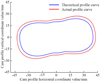 |
Fig. 5 “∞”-shaped cam profile curve. |
2.4 Cutting mechanism design
The cutting mechanisms are mainly divided into reciprocating and rotary types [30,31]. Considering better toughness of safflower filaments and the layout of the picking head structure, the reciprocating cutting method is selected to effectively reduce the damage to the filaments and the flowers and fruits. The cutting mechanism mainly consists of a handle and a blade, where the design of the blade and its motion parameters are the core factors determining the cutting. Improper design may lead to the situation where the safflower filaments are squeezed without breaking during cutting. Based on this, according to the results of preliminary tests, it is determined that the blade edge angle, cutting inclination, and cutting speed are the main factors affecting the cutting effect of the filaments. A force analysis model for filament cutting is established, as shown in Figure 6.
 |
Fig. 6 Force analysis diagram of filament cutting. 1. Upper blade 2. Lower blade 3. Small diameter of the corolla. |
2.4.1 Analysis of blade edge angle and cutting inclination angle
To ensure effective clamping and cutting of filaments by the blades during cutting, two blades were installed symmetrically. According to GB/T 1209.1-2009 “Agricultural Machinery-Cutter-Part 1: Assembly” and preliminary tests, the gap between the two blades L0 = 0.5 mm is determined. According to GB/T 1209.3-2009 “Agricultural Machinery-Cutter-Part 3: Moving Blade, Fixed Blade and Knife Bar”, the blade edge angle λ = 25° and the blade thickness d = 1.5 mm are selected. The cutting contact mechanics model established based on the force analysis of filament cutting in Figure 6 is shown in equation (11).
 (11)
(11)
where f1 and f2 represent the frictional force between the filament and blade, N; F1 and F2 represent the normal pressure exerted by the blade on the filament, N; α1, α2 represent the cutting inclination angle of the blade, °; and γ represents the angle of friction, °.
According to equation (11), it can be calculated that:
 (12)
(12)
During the cutting of safflower filaments, to prevent the filaments from slipping out of the cutter's edge, the cutting angle of the blade should satisfy α1 = α2 ≤ γ. From the previous analysis of the material characteristics of the safflower filaments, the friction angle is γ =20°. Based on the above analysis, the cutting angle of the blade α1 = α2 = 20° is selected as the reference value for the filament cutting performance test.
2.4.2 Cutting speed analysis
Assuming that all impact loads act directly at the cutting point, and the speed of the cutting blade remains constant, the filaments undergo elastic deformation due to the impact of the blade, leading to an increase in the local contact area between the filaments an blade. If the curvature effect of the contact interface between the blade and filament is ignored, combined the momentum theorem, the critical condition causing the filament to break can be determined as follows:
 (13)
(13)
where F is the cutting force (N); A is the contact area between the filament and the blade (mm2); σs is the ultimate stress when the filament breaks (Pa); t is the duration of the cutting action (s); m is the mass of the filament (g), and v is the cutting speed (mm/s).
The contact area A between the filament and the blade is as follows [32]:
 (14)
(14)
where l is the cutting depth of the blade (mm) and d is the blade thickness (mm).
The cutting depth of the blade at a constant cutting speed is as follows:
 (15)
(15)
Combining equations (13)–(17), the required cutting speed for the filament can be obtained as follows:
 (16)
(16)
The cutting speed of safflower filaments, blade edge angle, and cutting inclination are interrelated. According to the material characteristic parameters of safflower filaments in Table 1, when a peak cutting force F = 17.44 N, ideal cutting contact area A = 9.07 mm2, experimental parameter blade edge angle λ = 25°, and cutting inclination α1 = 20°, the critical cutting speed is 7.07 mm/s. As the cutting speed increases, the cutting resistance decreases, and the damage rate of the safflower filaments and flower balls increases. Based on the experimental data of the mechanical characteristics of filament cutting [33,34], the cutting speed is determined to be in the range of 7–20 mm/s, a reference value for the performance factors of filament testing.
3 Results and analysis
3.1 The simulation test results of the ANSYS/LS-DYNA picking head analysis
Before the prototype of the harvester head is made, the cutting process of the safflower filaments is simulated using the explicit dynamics simulation software ANSYS/LS-DYNA [35,36]. A simulation model of the interaction between the safflower filaments and cutter blade is established by comparing the cutting effects of different blade angles, cutting inclination angles, and cutting speeds on the filaments.
3.1.1 Establishment and parameter setting of the simulation model
The simulation model mainly includes the safflower plant and harvester head cutting models. During cutting, the harvester head comes into contact and collides with the safflower fruit ball and filaments, which can be simplified as a nonlinear transient dynamics problem. To improve the computational efficiency in modeling, a single flower fruit and filament are used as a simplified model of the safflower plant, with the filament as the free end and the flower fruit and stem as a whole as the fixed end. Similarly, the harvester head model only retains two cutting blades, ignoring other parts such as the “∞”-shaped cam, fixed disc, and sliding handle. The two cutting blades are modeled according to the cutting inclination angle for assembly. The simulation model is shown in Figure 7.
The properties of safflower filaments are those of a flexible body material, which has many physical characteristics during cutting. Based on previous studies [37], the flower fruit and stem are considered as rigid body materials without deformation, and the physical model parameters of the safflower plant are shown in Table 3. The material properties of the cutting blades are as follows: GB/T 1209.3-2009 Agricultural Machinery-Cutters-Part 3: Moving Blades, Fixed Blades, and Cutter Bars. The parameters are shown in Table 3.
The contact between the cutting blade and the filament is surface contact erodsion, with a dynamic friction coefficient of 0.15 and a static friction coefficient of 0.5. Multi-region meshing is used to refine the mesh at a smaller diameter of safflower filament. In this way, the translational degrees of freedom of the blade in the y-z axis direction, as well as fully the bottom of the safflower stem can be fully constrained. After all parameter are set, a .K file is generated. To make the filament with a small diameter break under stress, it is necessary to enter the keyword * MAT_ADD_EROSION in .K file and solve it in the Mechanical APDL to obtain the d3plot file [37,38]. The LS-Prepost post-processing program is then used to analyze the motion parameters of the blade and filament.
 |
Fig. 7 Simulation Model. 1. Safflower Filament 2. Cutting Blade 3. Flower Fruit 4. Stem. |
Material parameters of safflower plants and cutting blade.
3.1.2 Cutting process simulation and conclusion analysis
Effect of different blade edge angles on the mechanical properties of safflower filament cutting is analyzed. Under average ideal cutting inclination and speed, different blade edge angles (20°, 25°, 30°) are used to cut safflower filaments. The simulation analysis results are shown in Figure 8. In the initial stage of cutting, safflower filaments mainly bear compressive stress and the shear stress at the blade edge increases rapidly due to inherent toughness of safflower filaments and the impact force generated by blade. At the same time, the stress at the contact point between the safflower filament and fruit also begins to increase. As the blade cuts deeper, the maximum shear stress will fluctuate dynamically until the safflower filament is completely cut. At this point, the maximum shear stress drops to 0 N, and the cutting power consumption tends to stabilize after increasing. Due to the constraint at the lower end of the filament, the stress at the connection of the filament and fruit changes. Specifically, when the blade edge angle is 20°, the maximum shear stress of the safflower filament reaches 0.792 MPa, and the maximum cutting force is 7.18 N. When the blade edge angle is adjusted to 25°, the maximum shear stress of the safflower filament is 0.438 MPa, and the maximum cutting force is 3.97 N. When the blade edge angle is adjusted to 30°, the maximum shear stress of the safflower filament is 0.461 MPa, and the maximum cutting force is 4.18 N. The results show that the peak shear stress is the lowest when the blade edge angle is 25°, making the filament easier cut and the cutting success rate increase.
Influence of different cutting inclinations on mechanical properties of safflower filament cutting: Under the average ideal blade edge angle and cutting speed, the simulated stress-strain cloud diagrams of safflower filament at different cutting inclinations (15°, 20°, 25°) are shown in Figure 9. In the simulation, when the cutting inclination is set to15°, the maximum shear stress of the safflower filament is 0.636 MPa, and the maximum cutting force is 5.77 N. When the cutting inclination is set to 20°, the maximum shear stress of the safflower filament is 0.438 MPa, and the maximum cutting force is 3.97 N. When the cutting inclination is set to 25°, the maximum shear stress of the safflower filament is 0.668 MPa, and the maximum cutting force is 6.06 N. The simulation results indicate that when the cutting inclination is set to 20°, the cutting effect is optimal.
Influence of different cutting speeds on mechanical properties of safflower filament cutting: Under the average ideal blade edge angle and cutting inclination, the simulated stress-strain cloud diagrams of the safflower filament at different cutting speeds (7, 15, and 20 mm/s) are shown in Figure 10. In the test, when the cutting speed is set to 7 mm/s, the maximum shear stress of the safflower filament is 0.545 MPa, and the maximum cutting force is 4.94 N. When the cutting speed is set to 15 mm/s, the maximum shear stress of the safflower filament is 0.438 MPa, and the maximum cutting force is 3.97 N. When the cutting speed is set to 20 mm/s, the maximum shear stress of the safflower filament is 0.788 MPa, and the maximum cutting force is 7.15 N. The test results show that when the cutting speed is set to 15 mm/s, the cutting effect of safflower filaments is optimal.
Comparing and analyzing the simulations of different blade edge angles, cutting inclinations, and cutting speeds, the optimal parameters affecting the cutting effect of filaments are determined. The stress variation pattern of safflower filaments under dynamic cutting load is revealed, aiming to provide a reference for the performance testing of the safflower filament cutting test bench and interactive analysis sunder different factors.
 |
Fig. 8 Influence of different blade edge angles on the mechanical properties of safflower filament cutting. (a) Blade edge angle 20°. (b) Blade edge angle 25°. (c) Blade edge angle 30°. |
 |
Fig. 9 Influence of different cutting inclinations on the mechanical properties of safflower filament cutting. (a) Cutting inclination 15°. (b) Cutting inclination 20°. (c) Cutting inclination 25°. |
 |
Fig. 10 The influence of different cutting speeds on the mechanical properties of safflower filament cutting. (a) Cutting speed 7 mm/s. (b) Cutting speed 15 mm/s. (c) Cutting speed 20 mm/s. |
3.2 Analysis of the performance test results for the picking head
To further optimize the structure and operating parameters of the picking head and ensure the cutting effect of safflower filaments, based on theoretical and simulation, picking heads with different blade angles were prefabricated. A safflower filament picking head performance test bench was set up as shown in Figure 11. The test bench mainly consisted of a frame, CP1E-N20DT-A PLC, power box, picking head, stepper motor, drivers, and ball screw slide table. The picking head is mounted on the slider of the ball screw slide table, and its height is controlled by the lifting motor, which is connected to the “∞”-shaped cam of the picking head. The reciprocating cutting of the blades is achieved through rotation, with the entire system being controlled by the PLC.
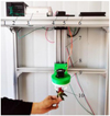 |
Fig. 11 Safflower Filament Picking Head Performance Test Bench. 1. Frame 2. PLC 3. Power Box 4. Lifting Motor 5. Driver a 6. Driver b 7. Ball Screw Slide Table 8. Cutting Motor 9. Picking Head 10. Safflower. |
3.2.1 Evaluation indicators
In this experiment, the success rate of filament cutting is used as an evaluation indicator. It is the percentage of the number of filaments cut from the flower fruit by the blades when the “∞”-shaped cam of the picking head rotates half a circle, to the total number of filaments on the flower fruit. It can be calculated as follows:
 (17)
(17)
where W-Cutting success rate, %; M-Number of filaments cut, pcs; N-Total number of filaments on the flower fruit, pcs.
3.2.2 Test factors
Cam Speed x1: The cutting speed during the picking head cutting process is difficult to directly control, but the “∞”-shaped cam speed is precisely controlled by the stepper motor and is related to the driven cutting blade. Therefore, the cutting speed can be determined by controlling the cam speed. Based on previous mechanical characteristic tests and theoretical analysis, the relationship between cam speed and cutting speed can be expressed by equation (18), and the cam speed range can be set to 25–67 r/min.
 (18)
(18)
Blade Edge Angle x2: To reduce the resistance when the blade interacts with the filaments, combined with the aforementioned research and analysis, the blade edge angle range is selected as 20–30°.
Cutting Tilt Angle x3: Considering the sliding cutting effect and lodging damage of filaments according to the installation structure of the picking head blade, combined with the aforementioned research and analysis, the cutting tilt angle range is selected as 15–25°.
3.2.3 Experimental scheme
This experiment adopts the Central Composite Design (CCD) method to explore the optimal combination of parameters for the success rate of cutting filaments [39,40], including camshaft speed x1, blade edge angle x2, and cutting inclination angle x3. The experiment was arranged according to three factors at five levels, as shown in Table 4. The experimental scheme is shown in Table 5. Each set of experiments was repeated thrice to obtain an average value.
Coding of factors and levels.
Experimental scheme and results.
3.2.4 Establishment of regression model and significance test
The variance analysis results of each factor on the cutting success rate are shown in Table 6. Design-Expert 12.0 software is used to process the data in Table 5 and perform multiple regression fitting. A P < 0.0001 indicates that this regression model is highly significant. x1, x2, x3, x1x3, x12, x22, and x32 have a highly significant impact on the cutting success rate model; x2x3 has a significant impact on the cutting success rate model, and x1x2 has an insignificant impact on the cutting success rate model. The determination coefficient R2 is 0.9753; the lack-of-fit item P is 0.1589, and the signal-to-noise ratio is 20.4297. This indicates that the arrangement of the experimental data is reasonable with high fitting, which can fully reflect the relationship between various factors and the cutting success rate. According to the results of variance analysis, the insignificant factors are eliminated, and the quadratic regression equation of the three factors on the cutting success rate is obtained as follows:
 (19)
(19)
Analysis of variance for regression model.
3.2.5 Effect of interaction between experimental factors on cutting success rate
As shown in Figure 12a, the interaction between the camshaft speed and cutting inclination angle will affect the cutting success rate. When the blade edge angle is fixed at level 0 (x2 = 25°), as the camshaft speed and cutting inclination angle increase, the success rate first increases and then decreases. The elliptical contour lines with large curvatures indicate that the influence of camshaft speed on the cutting success is more significant than that of cutting inclination angle. When the camshaft speed is 23–47 r/min and the cutting inclination angle is 16–23°, the cutting success rate is higher.
As shown in Figure 12b, the interaction between the blade edge angle and the cutting inclination angle will affect the cutting success rate. When the camshaft speed is fixed at level 0 (x1 = 46°), as the blade edge and cutting inclination angles increase, the success rate first increases and then decreases. The elliptical contour lines with large curvatures indicate that the influence of the blade edge angle on the cutting success rate is slightly greater than the cutting inclination angle. When the blade edge angle is between 16° and 24° and the cutting inclination angle is between 17° and 22°, the success rate is higher.
 |
Fig. 12 Effects of factor interaction on cutting success rate. |
3.2.6 Optimization and verification of optimal parameter combination
To obtain the optimal operating parameters for the filament-cutting head, based on the requirements of safflower filament harvesting and the above analysis results, three factors are optimized using the Optimization-Numerical module in Design-Expert 12.0 software. The objective function and constraints are as shown in equation (20). The combination of optimal parameters is a camshaft speed of 32.6 r/min, a blade edge angle of 22.5°, and a cutting inclination angle of 19.6°. At this point, the cutting success rate for safflower filaments is 92.84%.
 (20)
(20)
To further verify the reliability of the optimized parameters, five repeated bench tests were conducted under this combination, as shown in Figure 13. The average success rate for cutting filaments is 90.5%, with an experimental value not exceeding an error of 2.5% compared to the theoretical optimum value. The optimization model is reasonable and feasible, meeting the design requirements for the safflower filament-cutting head.
 |
Fig. 13 Experimental verification. 1. Filament cutting 2. Cutting effect. |
4 Conclusion
To address the disadvantages in manual harvesting, scarcity of mechanized harvesting, and high damage rate of safflower filaments, a specialized picking head for automated safflower filament collection is designed. Through centering on the filament-cutting model, the work parameters of the picking head are optimized and validated. The main findings and conclusions are as follows:
Through experimental analysis of the characteristics of safflower materials, a model of safflower growth morphology and features was established. The design requirements for mechanical harvesting structures during safflower harvesting and the setting parameters for dynamic simulation models are clarified.
Based on the requirements of safflower filament harvesting, an overall structural design for the picking head is developed and the core components-specifically the cam and cutting blade, are optimized. An innovative “∞”-shaped cam profile curve is proposed, enabling each rotation of the picking head to cut two filaments, significantly enhancing the operational efficiency while reducing overall power consumption. Theoretical analysis has determined the optimal range of blade angle, cutting inclination angle, and cutting speed.
Comparative simulation analysis assesses the effects of varying blade edge angles, cutting inclination angles, and cutting speeds on the mechanical properties of filament cutting. The results indicated that at a blade edge angle of 25°, a cutting inclination angle of 20°, and a cutting speed of 15 mm/s, the optimal cutting stress (0.438 MPa) and cutting force (3.97 N) are obtained.
A test platform for cutting mechanism of the safflower picking head is constructed, and the Central Composite Design (CCD) method is used for experimental design. A regression model is established to relate cutting success rate to three factors: blade edge angle, cutting inclination angle, and cam rotation speed. The analysis results reveal that cam rotation speed has a significantly greater effect on the cutting success rate than the cutting inclination angle, with the blade edge angle showing a slightly higher impact than the inclination angle. The optimal ranges for these parameters are identified, with the optimal parameter combination as a cam rotation speed of 32.6 rpm, a blade edge angle of 22.5°, and a cutting inclination angle of 19.6°. Under these optimized conditions, the cutting success rate of safflower filaments reaches 92.84%. Five repeated bench tests under these conditions yield a cutting success rate of 90.5%, with an error margin of less than 2.5% from the theoretical optimum. This indicates the validity and feasibility of the optimization model, meeting the design requirements of the picking head for safflower filaments.
Although this study has met the performance requirements for automatic harvesting of safflower filaments, further optimization and improvement are needed to promote the practical application of the equipment. Future research should focus on the following aspects: Adaptive Adjustment Mechanism: In the structural design of the picking head, an adaptive adjustment mechanism would be developed to enable the picking head to automatically modify parameters based on real-time characteristic detection of safflower filaments. Intelligence Level: Integrate machine vision and artificial intelligence algorithms, combining sensor technology with control systems to real-time equipment detection and automatic adjustment of harvesting actions. Practical Application and Economic Analysis: Emphasize is placed on evaluating the practical effectiveness and economic viability of the equipment to promote large-scale field application of safflower filament harvesting devices, providing robust technical support for the advancement of the safflower cultivation industry.
Funding
This research was funded by the second batch of Tianshan Talent Cultivation Plan for Young Talent Support Project (Program No. 2023TSYCQNTJ0040), and the Natural Science Basic Research Program of Shaanxi (Program No. 2023-JC-YB-347).
Conflicts of interest
The authors have no conflict of interest to report.
Data availability statement
Not applicable.
Author contribution statement
Conceptualization, Bangbang Chen and Feng Ding; Methodology, Baojian Ma; Data Curation, Xiangdong Liu; Formal Analysis, Shanping Ning; Writing-Original Draft Preparation, Bangbang Chen, Feng Ding and Shanping Ning; Writing-Review & Editing, Baojian Ma and Xiangdong Liu. All authors contributed to the study conception and design. All authors read and approved the final manuscript.
References
- National Pharmacopoeia Commission Pharmacopoeia of the People's Republic of China (China Medical Science and Technology, Press Beijing, 2020), p.232–233 [Google Scholar]
- Z.H. Wu, Research progress summary of Chinese medicine safflower, World Latest Med. Inform. 19, 33–34 (2019) [Google Scholar]
- Z. Chen, Application of characteristic volatile aroma analysis of Xinjiang safflower seed oil in quality control, M.S. thesis, Dept. Food Sci., Shihezi University, Shihezi, China (2018) [Google Scholar]
- H.H. Mündel, J.W. Bergman, Safflower, Oil Crops. 4, 423–447 (2010) [Google Scholar]
- C.X. Ren, Y.Y. Wu, X.H. Tang, J. Hu, J. Chen, Q.H. Wu, J. Pei, Safflower's origin and changes of producing areas, China J. Chin. Mater. Med. 42, 2219–2222 (2017) [Google Scholar]
- Y. Zhou, J. Guo, X. Ma, X. Fan, Y. Chen, M. Lin, Research on current situation and development countermeasures of Xinjiang safflower production, J. Anhui Agric Sci. 49 (19), 199–201+217 (2021) [Google Scholar]
- Technical specifications for safflower planting and collection, China Entry-Exit Inspection & Quarantine Association Standard T/CIQA 46-2023, 2023 [Google Scholar]
- W.L. Sun, W.B. Cao, L.L. Gu, J.D. Liu, S.H. Wang, Design and validation of gripping picking mechanism based on safflower mechanical properties, J. Agric. Mech. Res. 40, 46–51 (2018) [Google Scholar]
- Y. Ge, L.X. Zhang, D.D. Han, J.P. Chen, W. Fu, Current state and development trend of the mechanical harvesting on saffron filaments, J. Agric. Mech. Res. 36, 265–268 (2014) [Google Scholar]
- Aziguli, Current state and development of the mechanical harvesting on saffron filaments, Xinjiang Agric. Mech. 04, 7–10 (2014) [Google Scholar]
- S. Azimi, G.R. Chegini, M. Kianmehr, A. Heidari, Design and construction of a harvesting safflower petals machine, Mech. Ind. 13, 301–305 (2012) [CrossRef] [EDP Sciences] [Google Scholar]
- A.M. Bertetto, R. Ricciu, M.G. Badas, A mechanical saffron flower harvesting system, Meccanica 49, 2785–2796 (2014) [CrossRef] [Google Scholar]
- D. Ehlert, K. Beier, Development of picking devices for chamomile harvesters, J. Appl. Res. Med. Aromatic Plants 1, 73–80 (2014) [Google Scholar]
- J. Gu, The design and research of roller safflower harvest machine. M.S. thesis, Dept. Mech. Eng., Shihezi University, Shihezi, China (2016) [Google Scholar]
- Y.B. Chen, Y. Ge, D.D. Liang, X.P. Jiao, G.X. Liu, Design and research of the roller type safflower harvest test bed, J. Agric. Mech. Res. 39, 38–41+52 (2017) [Google Scholar]
- X.W. Zhang, Y. Ge, F. Chen, P.F. Yu, Design of three-finger pull-out safflower picking end effector, Mach. Des. Manufact. 01, 145–149 (2022) [Google Scholar]
- W. Cao, G. Lian, C. Niu L. An, S. Yang, B. Chen, Harvest performance test and parameter optimization of comb-type safflower-filaments picking head at same height, Trans. Chin. Soc Agric. Eng. 34, 36–44 (2018) [Google Scholar]
- Z.G. Zhang, Q.G. Lv, Y.J. Ren, C.J. Han, P.P. Yuan, X.J. Zhang, Design of critical components for safflower harvesting machinery by rotary shear, J. Chin. Agric. Mech. 40, 1–6 (2019) [Google Scholar]
- D. Luo, Design and Research of a Safflower Picking Device based on a Parallel Manipulator. M.S. thesis, Dept. Mech. Eng., Xinjiang Agricultural University, Urumqi, China (2022) [Google Scholar]
- H. Guo, H. Lu, G.M. Gao, T.L. Wu, H.Y. Chen, Z.X. Qiu, Design and test of a levelling system for a mobile safflower picking platform, Appl. Sci. 13, 4465 (2023) [CrossRef] [Google Scholar]
- H. Guo, H.Y. Chen, G.M. Gao, W. Zhou, T.L. Wu, Z.X. Qiu, Safflower corolla object detection and spatial positioning methods based on YOLOv5m, Trans. Chin Soc. Agric. Mach. 54, 272–281 (2023) [Google Scholar]
- X.R. Wang, Y. Xu, J.P. Zhou, J.R. Chen, Safflower picking recognition in complex environment based on improved YOLOv7, Trans. Chin. Soc. Agric. Eng. 39, 4465 (2023) [Google Scholar]
- A. Ranjan, R. Machavaram, P. Patidar, Design and development of a peduncle-holding end effector for robotic harvesting of mango, Cogent Eng. 11, 2403706 (2024) [CrossRef] [Google Scholar]
- S. Zeba, R. Laishram, G. Anand, Design and Development of Robots End Effector Test Rig. arxiv preprint arxiv:2101.00875 (2021) [Google Scholar]
- Y. Chen, Y. Wu, Design and application innovation of cam mechanism (China Machine Press, Beijing, 2007), pp. 20–53 [Google Scholar]
- H. Wang, Z. Li, X. Jiang, H. Nie, L. Geng, Design and experiment on blueberry picking machine based on groove cam drive, Trans. Chin. Soc. Agric. Mach. 49, 80–91 (2018) [Google Scholar]
- G. Quaglia, M. Nisi, Design of a self-leveling cam mechanism for a stair climbing wheelchair, Mech. Mach. Theory 112, 84–104 (2017) [CrossRef] [Google Scholar]
- J. Pozo-Palacios, N.J. Fulbright, J.A. Voth, J.D. Van de Ven, Comparison of forward and inverse cam generation methods for the design of cam-linkage mechanisms, Mech. Mach. Theory 190, 105465 (2023) [CrossRef] [Google Scholar]
- B.L. Ye, L. Li, G.H. Yu, A. Liu, D. Cai, Design and test on cam mechanism of seedling pick-up arm for vegetable transplanter for pot seedling, Trans. Chin. Soc. Agric. Eng. 30, 21–29 (2014) [Google Scholar]
- F. Kang, S.Y. Tong, H.S. Zhang, W.B. Li, Z.J. Chen, Y.J. Zheng, Analysis and experiment of reciprocating cutting parameters for apple tree branches, Trans. Chin. Soc. Agric. Eng. 36, 9–16 (2020) [Google Scholar]
- F.T. Kong, D.F. Wang, L. Shi, T. Wu, C.L. Chen, Y.F. Sun, Q. Xi, Design and experiment of disc-cutting picking device of castor, Trans. Chin. Soc. Agric. Eng. 37, 1–9 (2021) [Google Scholar]
- L. Wang, Z. Zhang, T. Liu, Y. Wang, F. Jia, J. Jiang, Design and experiment of device for chopping stalk of header of maize harvester, Trans. Chin. Soc. Agric. Mach. 51, 109–117 (2020) [Google Scholar]
- K. Wu, Y.P. Song, Research progress analysis of crop stalk cutting theory and method, Trans. Chin. Soc. Agric. Mach. 53, 1–20 (2022) [Google Scholar]
- Z. Zhang, M. Zhao, Z. Xing, X. Liu, Design and test of double-acting opposite direction cutting end effector for safflower harvester, Trans. Chin. Soc. Agric. Mach. 53, 160–170 (2022) [Google Scholar]
- Y.L. Cao, Y. Yu, Z. Tang, Y.F. Zhao, X.Y. Gu, S.F. Liu, S.R. Chen, Multi-tooth cutting method and bionic cutter design for Broccoli Xylem (Brassica oleracea L. var. Italica Plenck), Agriculture 13, 1267 (2023) [Google Scholar]
- X. Huan, Y. You, D. Wang, S. Li, L. Zhu, Y. Liao, Design and experiment of rotary cutter disc type flat stubble cutting device for king grass harvester, Trans. Chin. Soc. Agric. Mach. 53, 112–124 (2022) [Google Scholar]
- W.B. Cao, W. Sun, C. Niu, H. Jiao, B. Chen, Combed safflower picking device based on ANSYS/LS-DYNA, Trans. Chin. Soc. Agric. Mach. 49, 123–131 (2018) [Google Scholar]
- Y. Zhang, Experimental study on cutting mechanical properties of coarse cereals stem related to mechanical harvest. Ph.D. dissertation, Dept. Mech. Eng., Shanxi Agricultural University, Shanxi, China (2019) [Google Scholar]
- X.N. Zhang, Y. You, D.C. Wang, Z.Y. Wang, Y.Y. Liao, J. Lu, Design and experiment of soil-breaking and root-cutting cutter based on discrete element method, Trans. Chin. Soc. Agric. Mach. 53, 176–187 (2022) [Google Scholar]
- Z.M. Zhao, X.X. Zhu, J.C. Li, J.Q. Lyu, Y. Qi, J.N. Liu, Design and test of an arc-shaped tooth press device for combined soil preparation equipment for growing potatoes, Agriculture 13, 1193 (2023) [CrossRef] [Google Scholar]
Cite this article as: B. Chen, F. Ding, B. Ma, X. Liu, S. Ning, Design and experimental verification of the picking cam mechanism for safflower filaments, Mechanics & Industry 25, 34 (2024)
All Tables
All Figures
|
Fig. 1 Measurement of characteristic parameters of safflower materials. |
| In the text | |
|
Fig. 2 Schematic diagram of the harvesting head device structure. 1. Housing 2. “∞”-shaped cam 3. Roller bearing 4. Fixed disc 5. Driven rod 6. Sliding knife handle 7. Blade 8. Safflower 9. Stepper motor. |
| In the text | |
|
Fig. 3 Schematic diagram of the cam working segments. |
| In the text | |
|
Fig. 4 Motion curve of the moving part handle. |
| In the text | |
|
Fig. 5 “∞”-shaped cam profile curve. |
| In the text | |
|
Fig. 6 Force analysis diagram of filament cutting. 1. Upper blade 2. Lower blade 3. Small diameter of the corolla. |
| In the text | |
|
Fig. 7 Simulation Model. 1. Safflower Filament 2. Cutting Blade 3. Flower Fruit 4. Stem. |
| In the text | |
|
Fig. 8 Influence of different blade edge angles on the mechanical properties of safflower filament cutting. (a) Blade edge angle 20°. (b) Blade edge angle 25°. (c) Blade edge angle 30°. |
| In the text | |
|
Fig. 9 Influence of different cutting inclinations on the mechanical properties of safflower filament cutting. (a) Cutting inclination 15°. (b) Cutting inclination 20°. (c) Cutting inclination 25°. |
| In the text | |
|
Fig. 10 The influence of different cutting speeds on the mechanical properties of safflower filament cutting. (a) Cutting speed 7 mm/s. (b) Cutting speed 15 mm/s. (c) Cutting speed 20 mm/s. |
| In the text | |
|
Fig. 11 Safflower Filament Picking Head Performance Test Bench. 1. Frame 2. PLC 3. Power Box 4. Lifting Motor 5. Driver a 6. Driver b 7. Ball Screw Slide Table 8. Cutting Motor 9. Picking Head 10. Safflower. |
| In the text | |
|
Fig. 12 Effects of factor interaction on cutting success rate. |
| In the text | |
|
Fig. 13 Experimental verification. 1. Filament cutting 2. Cutting effect. |
| In the text | |
Current usage metrics show cumulative count of Article Views (full-text article views including HTML views, PDF and ePub downloads, according to the available data) and Abstracts Views on Vision4Press platform.
Data correspond to usage on the plateform after 2015. The current usage metrics is available 48-96 hours after online publication and is updated daily on week days.
Initial download of the metrics may take a while.