| Issue |
Mechanics & Industry
Volume 26, 2025
|
|
|---|---|---|
| Article Number | 25 | |
| Number of page(s) | 10 | |
| DOI | https://doi.org/10.1051/meca/2025015 | |
| Published online | 05 August 2025 | |
Original Article
Failure analysis in disc shear based on Gissmo criterion
Technical Center of Tang Steel Company, HBIS Group, Tangshan 063000, China
* e-mail: This email address is being protected from spambots. You need JavaScript enabled to view it.
Received:
20
March
2025
Accepted:
3
July
2025
Abstract
To investigate the failure process of the strip during the shearing process of the disc shear, the forces acting on the upper shear blade of the disc shear, and the influence of various factors on the stress of the upper shear blade and the quality of shear section, a three-dimensional model of the disc shear was established based on the finite element method, and the Gissmo material failure criterion was introduced to analyse the stress of the upper shear blade and the quality of shear section under different lateral clearances, overlaps, and upper shear blade angles. The results demonstrate that the upper shear blade angle has the most significant impact on the stress of the upper shear blade, but has a marginal effect on shear section quality. Both the stress of the upper shear blade and the quality of shear section decrease with an increase in the upper shear blade angle. The lateral clearance has a certain impact on the stress of the upper shear blade, but its effect on quality of shear section is most significant. When the lateral clearance is 0.5 mm, the stress on the upper shear blade is minimized, but the quality of shear section is the poorest. The overlap has a negligible effect on both the stress of the upper shear blade and the quality of shear section in circular disc shearing. Finally, the simulation results are compared with actual production data, and it is found that the simulation results are basically consistent with the overall trend of actual results. In addition, the results of the model using the Gissmo failure criterion for the stresses on the shear blade are closer to the actual results than the results of the model using the constant strain failure criterion.
Key words: Gissmo / failure criterion / disc shear / stress / quality of shear section
© K. Xu et al., Published by EDP Sciences 2025
 This is an Open Access article distributed under the terms of the Creative Commons Attribution License (https://creativecommons.org/licenses/by/4.0), which permits unrestricted use, distribution, and reproduction in any medium, provided the original work is properly cited.
1 Introduction
The disc shear is a crucial piece of equipment in the metal strip production line. Its operating parameters directly affect both the edge quality of the steel strip and the service life of the disc shear [1]. The machine works in a continuous shearing mode. In this mode, tension is applied to the steel strip before it is sheared by the disc. After shearing, a tension roller ensures a clean cut. Disc shears are widely used in steel mills. However, when cutting high-strength steel, the upper blade often wears out quickly and the quality of the shear section deteriorates. This problem reduces production efficiency. Several factors influence the shear force and the quality of the cut. These include the lateral clearance, the overlap, the strip’s speed and thickness, and the strip’s material properties [2–10].
Researchers have studied these factors using simulations [3–8], experiments [5,9], and mathematical models [10–13]. Early simulation studies relied on the equivalent strain and maximum principal strain failure criteria. However, these criteria are not ideal for plate shear processes. Plate shear involves a tensile-shear composite failure process. The traditional criteria do not fully account for load paths or the cumulative effects of damage.
The study of failure theory and models has led to the development of several failure criteria that can characterise complex failure situations. One such model is the Gissmo fracture criterion. Based on the Johnson-Cook fracture model, it is well suited for analyzing failures in high-strength steel [14–17]. The Gissmo model considers plastic deformation, stress concentration, and variable failure strains under different stress triaxialities. It also accounts for the cumulative damage during loading [18]. Compared with conventional cutting theories or simpler failure models—such as the Mohr–Coulomb criterion or critical equivalent plastic strain models—GISSMO is capable of describing multiple failure mechanisms (e.g., shear, tension, or combined modes) within a single unified framework. This makes it particularly suitable for high-precision manufacturing applications, where materials are subjected to complex stress paths and strain localizations, as often seen in blanking, trimming, or disc shearing operations [19–23]. In recent years, GISSMO has seen growing adoption in mechanical manufacturing beyond its traditional use in vehicle crash simulations. For example, Lee et al. [24] applied GISSMO to predict crack initiation and propagation during the cold roll forming of aluminum alloy. Venturato et al. [25] used the model to optimize the formability of the high-strength steel in the precision stamping processes. Moreover, GISSMO has been successfully implemented to simulate fracture behavior in advanced high-strength steel components used in automotive structures, and even in self-piercing riveting [26,27].
In this work, a three-dimensional model of the disc shear is established based on the finite element method (FEM) and the Gissmo material failure criterion is introduced. The model is used to analyse and study the effects of lateral clearance, overlap, and upper shear blade angle on the stress of the upper shear blade and quality of shear section. The results provide a reference for optimizing the operation of the disc shear.
2 Gissmo material failure criterion
The Gissmo material failure criterion considers the accumulation of damage and the acceleration of damage in materials during loading.
 (1)
(1)
where ΔD is the damage accumulation, D is the damage value (the element is deleted when D=1), n is the damage exponent, η is the stress triaxiality, and εf (η) is the equivalent plastic strains for material failure at different stress triaxialities. The stress triaxiality can be expressed as follows:
 (2)
(2)
where σm is the hydrostatic stress, σeq is von mises stress, σ1, σ2 and σ3 denote principal values of Cauchy stress.
In addition, the Gissmo material failure criterion considers the impact of damage accumulation on a material’s ontological relationships. It modifies the material’s ontological curve by characterising the phenomenon of stress reduction with damage accumulation. Specifically, after the plastic strain of the material reaches the critical plastic strain, the flow stress decreases due to damage accumulation. The instability measure determines whether stress reduction occurs in a material. It is can be expressed as follows:
 (3)
(3)
where εcrit (η) is the fracture plastic strain associated with stress triaxiality. The instability factor, F, accumulates in each element during deformation and when F =1 the current value of D is stored as the critical damage value Dcrit. Material softening due to void nucleation and growth is approximated by reducing the element stress:
 (4)
(4)
where σ* is the reduced stress, σ is the current stress, and m is a fading exponent that is adjusted to control the rate of material softening.
3 Model simulation
Since our aim here is to establish a general understanding of the influence of lateral clearance, overlap, and upper shear blade angle on the stress of the upper shear blade and the quality of shear section, a simplified disc shear model is used to reduce the computational requirement while reasonable and general results can be acquired. The 3-D model of disc trimming shear is shown in Figure 1, the model was simplified and modeled based on the actual size of the disc shear. During the shearing process, the lower surface of the steel strip is made tangent to the lower disc shear to ensure surface quality near the shearing position. This position is set in the model. In this model, the disc shears is driven by the steel strip. The steel strip speed is constant. The disc shear is divided into two parts: the blade part and the disc part. The blade part is rigidly constrained to the disc part without any relative motion. The main object of study is the disc shear blade part. To ensure accurate calculations and minimize the amount of calculation required, refine the mesh of the disc shear blade (mesh size is 0.3 mm) and the mesh of the steel strip to be sheared and its surrounding area (mesh size is 0.02 mm). The finite element model exclusively consists of solid (3D) elements. The total model contains approximately 920,000 solid elements. The numerical simulation is performed using LS-DYNA, which is based on an explicit dynamic algorithm. The shear blade part of the material can only undergo elastic deformation during production, as plastic deformation is not possible. To minimize calculations, the disc part is set as the rigid material. DP800 exhibits a strain rate enhancement effect, making it sensitive to changes in strain rate. The stress−strain curves of DP800 at different strain rates are shown in Figure 2. The relationship between fracture plastic strain (εcrit), critical plastic strain (Dcrit) and stress triaxiality are shown in Figure 3 [20]. The simulation parameters are collected in Table 1.
During the shearing process, the strip is pulled through the disc shears at a constant speed. The upper and lower disc shears perform shearing operations on the strip. The strain distribution of the steel strip cross-section during the shearing process, the shape of the strip cross-section after shearing and the strain distribution of the shear section are shown in Figure 4.
When the shearing process begins, the steel strip undergoes elastic deformation as it is squeezed by the upper and lower shear blades of the disc shear. The lower surface of the steel strip is tangent to the lower shear disc of the disc shear, resulting in the upper shear blade squeezing a larger amount of the upper surface of the steel strip. The lower surface of the steel strip undergoes squeezing deformation due to the upper surface of the steel strip being squeezed by the upper shear blade. As the shear proceeds, some of the steel strip material reach its yield limit and undergo plastic deformation, particularly near the shear blade where bending and tensile deformation are the main types of deformation. As the strip is fed, the failure fractures appear on the upper and lower surfaces of the steel strip, which then continue to expand towards the interior of the steel strip. At this point, the primary deformation in the steel strip is shear deformation. When the cracks in both the upper and lower parts of the steel strip overlap, the shearing is complete.
Figure 5 shows the stress distribution on the disc shear blade for studying the stress during the shearing process.
It can be seen that, the stress concentration area on the upper shear blade is more outward than that on the lower shear blade. This is because that the upper shear blade first extrudes the steel strip, then the steel strip is deformed and comes into contact with the lower shear blade, which also extrudes it.
To investigate the stresses on the upper and lower shear blades during the shearing process and to verify mesh convergence, the mesh was refined by 50% and the maximum stresses on the upper and lower shear blades with time are extracted, as shown in Figure 6.
It can be observed that the maximum stress experienced by the upper shear blade during the shearing process is significantly higher than that on the lower shear blade. This finding aligns with the production observations, where the upper shear blade of disc shears tends to have a comparatively shorter lifespan. The reason for this is that, during the shearing process, the lower surface of the steel strip is tangent to the lower shear blade, while the upper shear blade exerts a larger amount of force on the strip. Extracting the stress triaxiality of the steel strip near the upper shear blade, it is close to 0, indicating that the shear stress is the primary force in it. Therefore, it can be assumed that the primary mode of failure for the steel strip section near the upper shear blade is shear failure. Extracting and analyzing the stress triaxiality of the steel strip near the lower shear blade, the primary mode of failure for the steel strip section near the lower shear blade is tensile-shear composite failure. According to the failure plastic strain-stress triaxiality curve, the largest failure plastic strain occurs when the stress triaxiality is 0. The main form of failure for the shear failure is near the upper shear blade of the strip, resulting in the maximum stress being higher on the upper blade of the shear process than on the lower shear blade. Therefore, the maximum stress on the upper shear blade during shearing is higher than the maximum stress on the lower shear blade, and the upper shear blade of the disc shear has a relatively short lifespan. Thus, in order to solve the issue of the upper shear blade’s short lifespan and ensure the quality of the shear section meets the required standards. It is necessary to investigate the the maximum stresses on the upper shear blade and the quality of the shear section at different conditions.
In additional, it can be found that the maximum stress remains essentially unchanged after mesh refinement, demonstrating that further mesh refinement has a negligible effect on the stresses.
 |
Fig. 1 Model of disc trimming shear. |
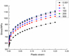 |
Fig. 2 Stress−strain curves of DP800 at different strain rates. |
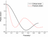 |
Fig. 3 Relationship between fracture plastic strain, critical plastic strain and stress triaxiality. |
Table of model parameters.
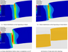 |
Fig. 4 Shearing process of steel strip. |
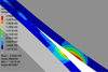 |
Fig. 5 Stress distribution on shear blade. |
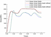 |
Fig. 6 Maximum stresses on the upper and lower shear blades with time. |
4 Results and discussion
The influences of some factors are investigated in this work, like lateral clearance, overlap, and upper shear blade angle.
4.1 Lateral clearance
The maximum stresses on the upper shear blade with time at different lateral clearances are measured and analyze. The results are shown in Figure 7.
It can be found that reducing the lateral clearance of the disc shear from 0.4 mm to 0.3 mm does not significantly affect the maximum stress on the upper shear blade. The reason is that when the disc shear lateral clearance is 0.4 mm, the main failure mode of strip is shear failure, and with the disc shear lateral clearance decreases, the f main failure mode does not change significantly.
In addition, it can be found that increasing the lateral clearance of the disc shear from 0.4 mm to 0.5 mm reduces stress on the upper shear blade. This is because that as the disc shear lateral clearance increases, the main failure mode of strip undergoes a transition from pure shear failure to tensile-shear composite failure, which means the plastic strain required for material failure is reduced (it can be seen from Fig. 3).
In order to observe the qualities of shear section at different lateral clearances, the shear sections are shown in Figure 8.
It can be seen that when the lateral clearance of the disc shear increases from 0.4 mm to 0.5 mm, the burrs are produced in the shear section and the quality of the edges decreases significantly. This finding aligns with production observations. The reason for this is that, with the disc shear lateral clearance increases, the strip part of the region of the force form of pure shear gradually transitions to tensile shear, resulting in the fracture deformation form of the consequent change.
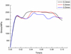 |
Fig. 7 Stress on the cutting edge of disc shears with different lateral clearances. |
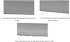 |
Fig. 8 The shear sections at different lateral clearances. |
4.2 Overlap
The maximum stresses on the upper shear blade with time at different overlaps are measured and analyze. The results are shown in Figure 9.
It can be observed that as the disc shear overlap decreases, the disc shear upper shear blade stress is slightly reduced. This is due to the fact that as the disc shear overlap decreases, the bite angle also decreases, while the component of force perpendicular to the direction of the strip increases. However, the reduction of the disc shear overlap does not significantly change the form of force and the failure plastic strain on the strip.
In order to observe the qualities of shear section at different overlaps, the shear sections are shown in Figure 10.
It can be observed that as the disc shear overlap decreases, the edge quality remains unchanged.
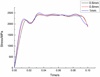 |
Fig. 9 Stress on the upper cutting edge of disc shear with different overlaps. |
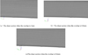 |
Fig. 10 The shear sections at different overlaps. |
4.3 Upper shear blade angle
The upper shear disc only contacts the surface of the steel strip scrap during the shearing process, not the finished product. Therefore, the increase in the upper shear blade angle will not affect the finished product’s surface quality. To study the effect of increasing the upper shear edge angle on the stress on the upper shear blade, the maximum stresses on the upper shear blade with time at different upper shear blade angles are measured. The results are shown in Figure 11.
It can be seen that with the disc shear upper shear edge angle increases, the disc shear upper shear edge stress significantly reduced. When the upper shear edge angle increases from 90° to 95°, the maximum stress on the upper shear edge is reduced by about 20%. The reason is that as the upper shear edge angle increases, the contact area between the upper shear edge and the strip steel increases, resulting in a reduction of the stress on the upper shear edge.
In order to observe the qualities of shear section at different upper shear blade angles, the shear sections are shown in Figure 12.
It can be observed that with the disc shear on the shear blade angle increases, the shear section quality slightly decreased. The reason is that with the shear blade angle increases, only a small amount of the original pure shear fracture deformation region converted to tensile shear fracture deformation region in the strip fracture process.
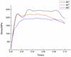 |
Fig. 11 Stress on the cutting edge of disc shears with different upper shear blade angles. |
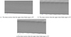 |
Fig. 12 The shear sections at different upper shear blade angles. |
4.4 Verification of simulation results
Due to the limited conditions of the existing equipment, it is not possible to make direct measurements of the stresses on the shear blade during the shearing process of disc shears. In order to verify the simulation results, the simulation results are compared with the actual production data.
In actual production practice, disc shear blades are regularly inspected and maintained once surface cracks or even severe edge breakage (“blade chipping”) is observed. It has been noted that when cutting ultra-high-strength steel under identical processing parameters, the service life of the blades tends to be significantly shorter and blade chipping becomes more frequent. The angular velocity of the disc shear is approximately 100 cycles/min. Moreover, according to the findings in the research [28–30], based on macroscopic and microscopic examinations of failed shear blades, the primary cause of surface cracks and chipping was identified as fatigue-related damage. These support the assumption that an increase in blade stress would correspond to a decrease in fatigue life.
Therefore, by comparing the effects of different factors on the lifespan of the disc shear blade in actual use, the influence of different factors on the stress on the shear blade can be obtained.
The stresses on the shear edge under different lateral clearances in the simulation results were extracted. In the simulation results, increasing the lateral shear clearance from 0.3 mm to 0.4 mm decreases the stress by 3%, increasing the lateral shear clearance from 0.3 mm to 0.5 mm decreases the stress by 10%. Collect and collate actual production data from production lines, the results shows that increasing the lateral shear clearance from 0.3mm to 0.4mm increases the lifespan by 10%, increasing the lateral shear clearance from 0.3mm to 0.5mm increases the lifespan by 21.4%. The overall trend of simulation results is consistent with the actual production results.
To compare the difference between the constant strain failure criterion and the Gissmo failure criterion in the stress calculation results of the disc shear blade, a disc shear constant strain failure criterion model was established, with the failure strain set to 1. The maximum stresses on the upper shear blade with time was measured as shown in Figure 13.
It can be seen that the lateral clearance has a negligible effect on the stress on the shear blade, which means that changing the lateral clearance has a negligible effect on the actual lifespan of the shear blade, which is contrary to the actual production data. Therefore, it can be considered that the results of the model using the Gissmo failure criterion for the stresses on the shear blade are closer to the actual results than the results of the model using the constant strain failure criterion.
The stresses on the shear edge under different overlaps in the simulation results were extracted. The result shows that as the overlap is reduced from 1 mm to 0.6 mm, there is no significant change in the stress, which is basically consistent with the actual production data.
The stresses on the shear edge under different blade angles in the simulation results were extracted. The result shows that as the blade angle is increased from 90° to 92°, and the stress is decreased by 13.8%. In order to verify the effect of the blade angle on the stresses on the shear blade, and taking into account the production stability and the edge quality, a disc shear with 92° blade angle was designed and manufactured as shown in Figure 14.
The disc shear with 92°blade angle was applied to actual production line for trial. Compared with the original disc shear, the disc shear with 92°blade angle two production results of lifespan increased by 21.8% and 27.1%, and in the trial process did not occur “chipping” phenomenon. In addition, there is a slight decrease in the edge quality of the product after shearing. The simulation results are basically consistent with the actual production verification results.
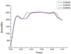 |
Fig. 13 stress on the cutting edge of disc shears with different lateral clearances. |
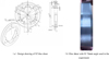 |
Fig. 14 Disc shear with 92° blade angle. |
5 Conclusions
In order to study the stress of the upper shear blade and quality of shear section, a three-dimensional model of the disc shear have been established based on the FEM and the Gissmo material failure criterion have been introduced to analyze the effect of the factors on the stress of the upper shear blade and quality of shear section in the present study. The factors simulated in the paper include the lateral clearance, the overlap, and the upper shear blade angle.
In terms of the ranges of factors investigated in the paper, the upper shear blade angle has the most significant impact on the stress of the upper shear blade, but has a relatively small influence on the quality of shear section. The stress on the upper shear blade decreases with the increase of the upper shear blade angle, and the quality of shear section decreases slightly with the increase of the upper shear blade angle. The lateral clearance has a certain impact on the stress of the upper shear blade, but its effect on quality of shear section is most significant. When the lateral clearance is 0.5mm, the stress on the upper shear blade is minimized, but the quality of shear section is the poorest. Under the present conditions, the overlap has a negligible effect on both the stress of the upper shear blade and the quality of shear section, and the stress on the upper shear blade decreases slightly as the overlap decreases. Finally, to validate the simulation results, the trends of simulated stress variation on the disc shear blade under different influencing factors were compared with the corresponding trends in blade service life from actual production under the same operating conditions. The results show that the simulation results based on the Gissmo failure criterion are in general agreement with the overall trend of the actual production results, which are closer to the actual results than the simulation results based on the constant strain failure criterion. This expands the applicability of GISSMO into an underexplored yet industrially significant domain.
Acknowledgments
The author would like to appreciate much for the anonymous reviewers and editors for improvement of this work, and Mrs.Wen Yang, Mr. Guo-ming Xu and Mrs.Lan-xiang Zhang for suggestions on this work.
Funding
Not applicable.
Conflicts of interest
No potential conflict of interest was reported by the authors.
Data availability statement
The data that support the findings of this study are available from the corresponding author, Xu Kuan, upon reasonable request.
Author contribution statement
Xu Kuan: Conceptualization, Methodology, Software, Investigation, Formal Analysis, Writing; Xia Ming-sheng: Resources, Supervision; Zhang Saijuan: Investigation; Wang Qiu-yu: Validation; Menggen Bagen: Data Curation.
References
- M.D. Ye, 100 questions about precision cutting of metal plate (Metallurgical Industry Press, Beijing, 2010) [Google Scholar]
- G.Y. Zhou, Finishing Equipment with Steel (China Machine Press, Beijing, 1982) [Google Scholar]
- P.S. Cao, Study on shear force of wide and thick plate rotary trimming shears, MSc thesis, Yanshan University (2023) [Google Scholar]
- W.C. Sun, Simulation of shear process and study of process parameters of rotary trimming shear, MSc thesis, Yanshan University (2023) [Google Scholar]
- W.S. Wang, Research on the influence mechanism of shearing process parameters on the shear quality of hydraulic rolling cut shear, MSc thesis, Taiyuan University of Science and Technology (2024) [Google Scholar]
- D.F. Li, S.L. Wu, W.J. Liu, Numerical analysis of shear force of side trimmer based on ANSYS/LS-DYNA, J. Plasticity Eng. 23, 56 (2016) [Google Scholar]
- Q.P. Jing, H.L. Jia, Y.H. Shuang, F. Yang, L. Jin, Numerical simulation and experimental study of the shearing process on trimming disc shear, J. Plasticity Eng. 17, 32 (2010) [Google Scholar]
- L.N. Tan, Y.Y. Chen, Simulation analysis of shearing process of disk shear strip based on ANSYS /LS-DYNA, J. Mech. Electrical Eng. 35, 122 (2018) [Google Scholar]
- Q.S. Yan, H. Li, Y.W. Zhu, J.B. Lu, Effect of shear clearance on the quality of cut surface of stainless steel sheets, Mach. Des. Manufact. 9, 59 (2021) [Google Scholar]
- Z.H. Bai, W. Lin, W. Wang, W.J. Zhang, X.T. Li, Development of optimization technology for disc shear process parameters of hot-dip galvanizing line, Iron Steel 57, 159 (2022) [Google Scholar]
- Z.B. Zhao, Y. Wang, M.Q. Qiu, Scale model of rolling-cut shear and its optimization design with all parameters, J. Machine Des. 40, 90 (2023) [Google Scholar]
- L.F. Ma, Q.X. Huang, Z.Q. Huang, Z.B. Chu, H.Y. Han, Energetic parameter test on disc shear of plate and establishment of the best blade clearance mathematical model, Chin. J. Eng. Des. 19, 434 (2012) [Google Scholar]
- X.B. Li, Discussion on shear principle of disc shear and analysis on shear force calculation, Mech. Res. Appl. 030, 55 (2017) [Google Scholar]
- J. Effelsberg, A. Haufe, M. Feucht, F. Neukamm, P. Dubois, On parameter identification for the GISSMO damage model, in 11th International LS-DYNA Users Conference, Metal Forming (2012), pp. 1–12 [Google Scholar]
- F. Neukamm, M. Feucht, K. Roll, A. Haufe, On closing the constitutive gap between forming and crash simulation, in 10th Internation LS-DYNA Users Conference 2008, Dearborn, Michigan, USA (2008) [Google Scholar]
- F. Neukamm, M. Feucht, A. Haufe, Considering damage history in crashworthiness simulations, in Proceedings of the 7th European LS-DYNA Users Conference, Salzburg, Austria: DYNAmore GmbH (2009), pp. 1–9. [Google Scholar]
- F. Andrade, M. Feucht, A. Haufe, On the prediction of material failure in LS-DYNA: a comparison between GISSMO and DIEM, in Proceedings of the 13th International LS-DYNA Users Conference, Detroit, USA (2014), pp. 1–10 [Google Scholar]
- H.L. Ma, Investigation of crashworthiness for hot stamping thin-wall structure considering damage, MSc thesis, Dalian University of Technology (2018) [Google Scholar]
- Livermore Software Technology Corporation, Ls-Dyna keyword user’s manual (Livermore Software Technology Corporation, USA, 2014). [Google Scholar]
- F.X.C. Andrade, M. Feucht, A. Haufe, F. Neukamm, An incremental stress state dependent damage model for ductile failure prediction, Int. J. Fracture 200, 127 (2016) [Google Scholar]
- D. Hrling, Parameter identification of GISSMO damage model for DOCOL 1200M: A study on crash simulation for high strength steel sheet components, MSc thesis, Karlstad University (2015) [Google Scholar]
- S.K. Chalavadi, Parameter identification of GISSMO damage model for DOCOL 900M high strength steel alloy: usage of a general damage model coupled with material modeling in LS-DYNA for Advanced high strength steel crashworthiness simulations, MSc thesis, Sweden: University West (2017) [Google Scholar]
- Y. Feng, S.N. Xiao, T. Zhu, B. Yang, G.W. Yang, Q.W. Che, Failure behavior and collision characteristics of energy-absorbing structures considering material failure criteria, J. Central South Univ. (Science and Technology) 2, 31 (2019) [Google Scholar]
- S.K. Lee, J.S. Lee, J.H. Song, J.Y. Park, G.H. Kim, Fracture simulation of cold roll forming process for aluminum 7075-t6 automotive bumper beam using gissmo damage model, Proc. Manufactur. 5, 15 (2018) [Google Scholar]
- G. Venturato, A. Ghiotti, S. Bruschi, Stress-state dependent formability modelling in hot stamping, Product. Eng. 9, 14 (2019) [Google Scholar]
- B. Gu, J. Lim, S. Hong, Determination and verification of gissmo fracture properties of bolts used in radioactive waste transport containers, Materials 15, 5 (2022) [Google Scholar]
- M. Otroshi, M. Rossel, G. Meschut, Stress state dependent damage modelling of self-pierce riveting process simulation using gissmo damage model, J. Adv. Joining Process. 100015 (2020) [Google Scholar]
- S.Z. Qamar, A. Fazal, M. Arif, A.K. Sheikh, M. Younas, T. Pervez, R.A. Siddiqui, Simulation of fatigue and wear life of extrusion dies, in Proceedings of the 10th International Research/Expert Conference (2014) [Google Scholar]
- M. Zhao, W.H. Wang, Analysis of crack and chipping causes of H13 disc shear blades and improvement measures, Tianjin Metall. 01, 145 (2008) [Google Scholar]
- L. Öman, Examination of a Damaged Slitting Knife using Scanning Electron Microscopy and Finite Element Simulations, MSc thesis, Karlstad University (2021) [Google Scholar]
Cite this article as: K. Xu, M.-S. Xia, S.-J. Zhang, Q.-Y. Wang, B. Menggen, Failure analysis in disc shear based on Gissmo criterion, Mechanics & Industry 26, 25 (2025), https://doi.org/10.1051/meca/2025015
All Tables
All Figures
|
Fig. 1 Model of disc trimming shear. |
| In the text | |
|
Fig. 2 Stress−strain curves of DP800 at different strain rates. |
| In the text | |
|
Fig. 3 Relationship between fracture plastic strain, critical plastic strain and stress triaxiality. |
| In the text | |
|
Fig. 4 Shearing process of steel strip. |
| In the text | |
|
Fig. 5 Stress distribution on shear blade. |
| In the text | |
|
Fig. 6 Maximum stresses on the upper and lower shear blades with time. |
| In the text | |
|
Fig. 7 Stress on the cutting edge of disc shears with different lateral clearances. |
| In the text | |
|
Fig. 8 The shear sections at different lateral clearances. |
| In the text | |
|
Fig. 9 Stress on the upper cutting edge of disc shear with different overlaps. |
| In the text | |
|
Fig. 10 The shear sections at different overlaps. |
| In the text | |
|
Fig. 11 Stress on the cutting edge of disc shears with different upper shear blade angles. |
| In the text | |
|
Fig. 12 The shear sections at different upper shear blade angles. |
| In the text | |
|
Fig. 13 stress on the cutting edge of disc shears with different lateral clearances. |
| In the text | |
|
Fig. 14 Disc shear with 92° blade angle. |
| In the text | |
Current usage metrics show cumulative count of Article Views (full-text article views including HTML views, PDF and ePub downloads, according to the available data) and Abstracts Views on Vision4Press platform.
Data correspond to usage on the plateform after 2015. The current usage metrics is available 48-96 hours after online publication and is updated daily on week days.
Initial download of the metrics may take a while.