


| Issue |
Mechanics & Industry
Volume 27, 2026
|
|
|---|---|---|
| Article Number | 33 | |
| Number of page(s) | 17 | |
| DOI | https://doi.org/10.1051/meca/2026030 | |
| Published online | 07 July 2026 | |
Original Article
Evaluation of thermoelectric generators for automotive waste heat recovery
Department of Mechanical and Materials Engineering, Faculty of Engineering, University of Jeddah, P.O. Box 80327, Jeddah 21589, Saudi Arabia
* e-mail: This email address is being protected from spambots. You need JavaScript enabled to view it.
Received:
7
August
2025
Accepted:
29
May
2026
Abstract
Thermoelectric generators (TEGs) are increasingly investigated for automotive exhaust waste-heat recovery in response to stringent fuel-efficiency regulations. This study numerically examines an air-cooled hybrid annular–rectangular TEG configuration integrated with external heat-sink modules to evaluate system performance under realistic automotive operating conditions. A three-dimensional numerical model was developed using COMSOL Multiphysics to investigate the influence of exhaust gas temperature (350–550 °C), exhaust mass flow rate (10–30 g/s), ambient air temperature (5–45 °C), and vehicle speed (40–120 km/h) on conversion efficiency and power output. The results show that the system achieves a maximum conversion efficiency of 12.3% at an exhaust temperature of 550 °C, an exhaust mass flow rate of 16 g/s, an ambient temperature of 5 °C, and a vehicle speed of 120 km/h, corresponding to an electrical power output of 314.7 W. Under maximum power conditions, increasing the exhaust mass flow rate to 30 g/s yields a peak power output of 559.3 W and an efficiency of 11.7%. Under representative automotive operating conditions (450 °C exhaust temperature, 20 g/s exhaust mass flow rate, 25 °C ambient temperature, and vehicle speed of 80 km/h), the system delivers 141 W of electrical power at an efficiency of 5.8%. The integration of air-cooled heat sinks enhances thermal dissipation while maintaining a pressure drop below 0.3 kPa, indicating a negligible impact on engine performance. These results demonstrate the feasibility of compact, air-cooled TEG systems for automotive waste-heat recovery and provide quantitative guidance for system-level design and optimization.
Key words: Thermoelectric generator / waste heat recovery / exhaust energy conversion / TEG design / COMSOL simulation
© S. Ghazali and A. Alkotami, Published by EDP Sciences, 2026
 This is an Open Access article distributed under the terms of the Creative Commons Attribution License (https://creativecommons.org/licenses/by/4.0), which permits unrestricted use, distribution, and reproduction in any medium, provided the original work is properly cited.
1 Introduction
Due to continuously rising energy requirements, there has been a greater focus on the research and development of waste heat recovery techniques. As one of the most common modes of transport, automobiles offer great convenience and speed but, in doing so, generate enormous amounts of waste heat. Statistics indicate that almost two-thirds of the energy produced by burning fuel in automobiles is lost as heat. Of this heat, nearly 40% is emitted into the atmosphere through the vehicle exhaust system [1]. By recovering and efficiently utilizing waste heat, it is possible to enhance the net energy efficiency of automobiles, thereby reducing harmful emissions and contributing to a cleaner, healthier environment. Among the numerous waste heat recovery technologies currently under investigation, the thermoelectric generator (TEG) is among the most promising for the future. The TEG is based on the Seebeck effect, a phenomenon in which thermal energy is converted into electricity using semiconductor materials. One of the most significant advantages of TEGs is that they are extremely simple to design, as they have no moving parts, making them easy to maintain, causing minimal pollution, and having an incredibly long lifespan. These attributes make TEGs a very likely candidate for energy efficiency in the motor industry [2]. Waste heat recovery (WHR) is a crucial issue in addressing global energy inefficiency and environmental problems. A significant portion of the energy consumed by today's industrial and automotive systems is lost as heat, leading to inefficient operation and environmental issues [3]. It is essential not only to maximize energy savings but also to mitigate the impacts of air pollution and greenhouse gas emissions, and to decrease reliance on fossil fuels. Manufacturers can help meet increasingly stringent emissions requirements and improve fuel economy by integrating these systems. The concept is to convert the stored energy in exhaust gases into usable forms, such as electricity, to power the vehicle or recharge its batteries. Waste heat recovery (WHR) technologies aim to capture and reuse heat that would be lost from industrial processes, engines, and power systems. Advanced technologies enable greater efficiency, reduced fuel use, and lower emissions. The WHR is divided into four categories: power cycles, exhaust gas turbine systems, combined systems, and thermoelectric generators (TEGs). Power cycles are used to recover waste heat and generate useful power, including the Brayton, Rankine, and CO2 Cycles. Exhaust gas turbine systems utilize harmful exhaust from engines or industrial processes to power turbines, producing additional energy. Combined systems that integrate different waste heat recovery methods to enhance efficiency, such as hybrid turbocharging and supercritical CO2 (SCO2) cycles. Finally, thermoelectric generators (TEGs), which utilize the Seebeck effect to convert heat directly into electricity using solid-state materials, form the foundation of this paper [4]. TEG devices are solid-state devices that directly convert thermal energy into electrical energy via DC and are an emerging technology for both energy harvesting and management.
Thermodynamic reversibility, whether from heat to electricity or vice versa, is a characteristic feature of TEGs, depending on the application. TEGs may be either coolers or power generators, with the benefit of their flexibility of use [5]. TEG systems are easy to use and maintain, with no moving components. They can capture waste heat from various sources, such as power stations or vehicle exhausts, and convert it into usable electricity. Apart from energy retrieval, Thermoelectric coolers have other applications, such as use in refrigeration equipment or medical devices [6]. There are three key effects involved in thermoelectric effects: The Seebeck effect, the Peltier effect, and the Thomson effect. They are interrelated and jointly characterize the relations between electric currents and temperature differences via the material. The Seebeck effect is the generation of an electric voltage when a temperature difference is established between two dissimilar conductors. The Peltier effect is the heating or cooling when an electric current passes through the junction of two dissimilar materials. Finally, the Thomson effect is the phenomenon in which a substance warms or cools when an electric current passes through it, thereby producing a temperature difference. These three effects are primarily crucial in thermoelectric devices, such as power generators and refrigerators [7].
Thermoelectric generators contain two types of semiconductor elements: P-type and N-type. The P-type element includes an excess of holes where electrons are absent, resulting in a net positive charge. The N-type element contains an excess of electrons with a net negative charge. Usually, the electrons in the N-type material acquire energy and move toward the P-type material because of the temperature gradient. This movement of charge carries electrons in the N-type and holes in the P-type, leading to an electrical current that can be harnessed as a power source [8]. The internal TEG configuration operates in series, ensuring a higher total voltage output because the voltage outputs from each pair of P-type and N-type semiconductors can be summed. This wiring is crucial for systems that require supplying higher voltages to power electrical devices or for charging batteries. TEGs can also be connected in parallel to optimize current output, providing flexibility in system design to adapt to specific power needs [9].
TEGs have unique advantages and disadvantages that affect their use in power generation. One of the best advantages of TEGs is that they have no moving parts, making them reliable and low-maintenance. This configuration also enables silent operation, a crucial factor for applications where noise reduction is essential. TEGs are an attractive option because they generate electricity without emitting pollutants or toxic waste products, which is a significant environmental benefit. Scalability is another factor that makes TEGs well-suited for use in small devices, such as handheld devices, as well as for scaling up to industrial applications. One key advantage is that they can harness waste heat from various sources, including engines, manufacturing processes, and body heat, to generate useful electrical energy. Finally, the long lifespans of the semiconductor materials involved result in a prolonged service life when suitably maintained. However, there are several disadvantages; one is the cost of thermoelectric materials like bismuth telluride, which makes them uneconomical for large-scale applications. TEGs also have a low operating temperature range, which usually requires extremely costly materials and necessitates specialist materials in hotter climates. Their efficiency depends on a large temperature gradient between the hot and cold sides, which may not be easily achieved in most real-world applications. TEGs typically produce relatively low electrical power compared to other power generation schemes and are therefore less suited to applications that require a large amount of energy. Proper thermal management is also essential; without the necessary temperature gradient, efficiency will suffer. Finally, the inadequacies of current thermoelectric materials, their limited thermal and electrical conductivity, still restrict the overall performance of these devices [10,11]. Extensive research in the field of thermoelectric generators and waste heat recovery systems. Several notable studies have provided valuable insights into the design, optimization, and application of TEGs [12–21]
Hyland et al. [22] investigated the use of thermoelectric generators to harvest electrical energy from human body heat to power wearable electronic devices. The work, conducted at the NSF ASSIST Center, involved experimental testing using a controlled hot plate and various body locations. Their findings highlight the feasibility of using body heat-powered TEGs for wearable healthcare monitoring systems, such as ECG sensors. Additionally, Chen et al. [23] investigated the application of four half-ring, polymer-based composite thermoelectric generators, designed to harness waste heat from hot water pipes. Using finite element analysis, the study explored the influence of heat sink surface area, half-ring thickness, and the air convection heat transfer coefficient on system performance. These parameters were found to play a critical role in determining device efficiency and achieving sufficient temperature differentials, offering valuable insights for the design and optimization of high-performance TEG systems for pipe-mounted waste heat recovery.
Other research investigated the optimization of flexible TEGs production for energy harvesting using a numerical approach. The calculations showed that a maximum tensile strength of 0.967 MPa and an output power of 11 μW were achieved, given a temperature difference of 75 °C. The use of flexible graphene in polydimethylsiloxane (PDMS) applications boosted thermal conductivity and doubled the output power to 0.0515 W. The Numerical model had a margin of error of 4.6% to 5.2%, confirming its accuracy [24]. This study is significant because it highlights the suitability of flexible TEGs for waste heat recovery, enhancing efficiency and sustainable energy generation. A critical analysis of the annular exhaust-based TEG system design by Zhou et al. [25] was conducted. Coolant flow rates were the focus for optimizing temperature gradients and preventing overheating, resulting in a peak net power output of 15 W. The emphasis of this research on annular configurations aligns closely with the aim of this paper, which is to maximize heat absorption from the exhaust manifold. The study influenced the decision to employ an annular arrangement, which enhanced efficiency and heat transfer.
Recent research has focused on high-output vehicle-level integrations. In a study by Zhao et al. [26], it was shown that annular geometries can significantly improve power output compared to conventional flat-plate geometries by minimizing contact resistance and maximizing the exhaust pipe's surface area. Another study by Luo et al. [27] addressed the scalability of TEGs by proposing stacked modular geometries with heat pipes to preserve temperature gradients. The study validated that it is theoretically possible to harvest kilowatt-scale power from heavy-duty vehicles. In addition, the current focus of TEG research on transient drive-cycle analysis, as proposed by Bhakta and Kundu [28], underscores the need for TEGs to harvest fluctuating heat fluxes encountered in a realistic driving cycle. These improvements in geometry and material stability [29] validate the maturity of circular TEGs from laboratory prototypes to vehicle-level integrations. Another study by S. Singh et al. [30] showed that optimizing the internal fin configuration in a circular TEG increased net power output by 14.2%, directly contributing to a 1.8% improvement in fuel economy, finally, L. Chen et al. [31] showed that by optimizing both mass flow rate and ambient airflow velocity, a net power increase of 18.4% can be achieved compared to single-variable control.
In addition to theoretical modeling, recent experimental developments have confirmed the feasibility of these systems. In particular, the work by Esen et al. [32] experimentally validated a 27-module system integrated into a gasoline exhaust system, achieving a stable 13V output, as required by automotive battery configurations. To reduce temperature fluctuations in the exhaust system, Li et al. [33] experimentally validated a two-stage system using phase-change materials, achieving a 27% increase in power generation over traditional single-stage systems. Additionally, Sukarno et al. [34] explored the use of heat pipe sinks, which are considered a major design feature for maintaining the high temperature gradient required for these systems within the limited space available in a vehicle framework. Based on previous research, circular thermoelectric generators (TEGs) have not been widely implemented in the automotive sector. Most research has focused on traditional flat-plate TEG configurations, with little investigation of circular geometries for waste-heat recovery in vehicles.
This study investigates an air-cooled hybrid annular–rectangular thermoelectric generator (TEG) configuration integrated with heat sink modules for automotive exhaust waste-heat recovery. Compared with previously reported water-cooled TEG systems, such as those described by Zhou et al. [25], the present work focuses on performance under realistic air-cooled operating conditions. The analysis considers the coupled effects of exhaust gas temperature (350–550 °C), exhaust mass flow rate (10–30 g/s), ambient air temperature (5–45 °C), and vehicle speed (40–120 km/h) on electrical power output and conversion efficiency. In addition to evaluating the influence of operating parameters, practical design aspects relevant to automotive integration, including pressure drop and heat sink thermal performance, are examined. The results allow the identification of operating conditions favoring either maximum efficiency or maximum power and highlight the associated thermal and hydraulic trade-offs. The findings provide insight into the potential of air-cooled TEG configurations and their applicability to automotive exhaust systems.
2 Model structure, numerical modelling and mathematical analysis
The model integrates various materials, each chosen for its specific properties, to improve overall performance. This section provides a detailed breakdown of the key parameters and materials, highlighting their characteristics and roles in enhancing the system's functionality. Additionally, the proposed model structure and its accompanying mathematical analysis are presented. Several factors affect the performance of thermoelectric generators; however, this paper focuses on those relevant to automotive applications. One of the most important factors is the temperature difference between the hot and cold sides of the TEG, as a greater gradient results in higher power output; therefore, maximizing this gradient is crucial. The temperature gradient depends upon the exhaust gas temperature, which varies from 350 °C to 550 °C, the ambient air temperature varies from 5 °C to 45 °C, and the rate at which air flows past the TEG varies from 10 g/s to 30 g/s, which depends upon vehicle speed, varying from 40 km/h to 120 km/h. The second key consideration is the choice and properties of the materials, which impact the performance. Although machinery is not lacking, several challenges arise when incorporating a TEG into an exhaust. There is typically limited space, so the balance space must be crafted as a small unit that is both complex and costly to build. The integration process itself is quite involved, for TEGs must interface with other components of the exhaust system, such as pipes and catalytic converters, while meeting emissions standards. In addition, exhaust systems are constantly vibrating and moving, which could stress the TEGs or cause failures if they are not firmly fastened or made from extremely hardy materials. Another issue will be thermal cycling, repeated heating and cooling, as in regular vehicle operation. This could cause material degradation over time; therefore, the TEGs should not lose efficiency under such conditions. The Figure of merit (ZT) is a critical parameter for quantifying the performance of thermoelectric materials and devices, such as TEGs. It is an accumulation of multiple material properties that signifies the efficiency with which a material can convert heat into electricity. Higher ZT indicates better thermoelectric performance.
Materials with a higher ZT can more effectively convert heat into electricity. Figure 1 illustrates the Fig. of merit (ZT) of various thermoelectric materials at a range of temperatures [35]. At around 400 K, Bismuth Telluride (Bi2Te3) has the highest Fig. of merit and hence is amongst the best thermoelectric materials at this range of temperature. Due to its excellent thermoelectric properties, such as a high Seebeck coefficient and good electrical conductivity, Bi2Te3 is widely regarded as the best material for low- to intermediate-temperature thermoelectric devices. Therefore, Bismuth telluride was selected as the material for this study, with average values of the Seebeck coefficient of 249 μV/K, the thermal conductivity of 1.75 W/m·K, and the electrical conductivity of 5.8824 × 10⁴ S/m. Bismuth achieves maximum efficiency for the given operating temperature and power generation conditions. There is also growing interest in advanced materials, such as skutterudites and half-Heusler alloys, which could offer improved performance in future applications.
2.1 Numerical modelling
This research uses COMSOL Multiphysics to simulate heat transfer and thermoelectric effects in a TEG that recovers heat from exhaust gas in an exhaust pipe. COMSOL is the best option for simulating thermoelectric effects in heat recovery because it provides a comprehensive modelling platform that analyses all physical interaction variables together. The COMSOL setup included heat conduction through thermoelectric materials, heat transfer through gases, and thermoelectric power generation via the Seebeck effect. A multiphysics simulation was then set up to integrate all these phenomena and evaluate waste-heat recovery, and to calculate TEG power output from exhaust and ambient temperatures. Figure 2 shows the annular exhaust-based TEG system used by Zhou et al. [25], which employed forced water circulation for cooling. This study will use Zhou's model as a comparison for the proposed new system, with a key difference: airflow circulation for cooling.
2.2 Boundaries, conditions, and the computational domain
It is assumed that the exhaust gas flow is steady during stable engine operation. The temperature gradient across the system depends on the exhaust gas temperature, which ranges from 350 °C to 550 °C, and the ambient air temperature, which ranges from 5 °C to 45 °C. The mass flow rate varies from 10 g/s to 30 g/s and is related to vehicle speed in the range of 40 km/h to 120 km/h. The outlet condition is a pressure outlet, and the coolant flows perpendicular to the exhaust gas flow to help keep the temperature even across the TEGs. The remaining exterior walls of the device are assumed adiabatic.
The simulation geometry was designed to represent a typical exhaust system integrated with thermoelectric modules, comprising TEGs, heatsinks, exhaust pipes, and a fluid domain. Two types of TEGs were used: a rectangular TEG, which is readily available on the market. The proposed model's dimensions for TEC1-12706 (40 × 40 × 4 mm) are used to study the design and structure of rectangular TEGs, as shown in Figure 3a. The system is provided with a breakdown of its components and working mechanisms. The core component of thermoelectric generators is the thermoelectric material, which in the model has a dimension of 1.4 × 1.4 × 1.6 mm. The n-type (electron-dense) and p-type (hole-dense) semiconductor materials are combined in a conductor material. The dimensions of the conductor material are 1.4 × 3.84 × 0.4 mm. Figure 3b shows the rectangular TEG, comprising 126 thermocouples, for a total of 252 elements. The elements are 1.04 mm apart and connected in series for the highest voltage output. An external connector is then used to complete the circuit, enabling effective power transfer. The same internal and external ceramic plates are fabricated to facilitate efficient heat transfer while simultaneously insulating the electrical circuit to prevent energy loss. Measuring 40 × 40 × 0.8 mm, these plates are crucial for providing thermal conductivity and ensuring the overall performance and safety of the system. The plate material was aluminum, with a thermal conductivity of 27 W/m.K. The second type of TEGs is the circular one, which is not commercially available in large quantities, but a model was made to meet special requirements.
Figure 3c shows the optimized circular TEG with an inner radius of 57 mm, a thickness of 4 mm, and a length of 120 mm. The elements of the circular TEG are arranged in a ring. The cross-sectional area of each element is identical to that of the rectangular TEG, which is 1.4 × 1.4 mm. The ring's internal diameter is also 59.4 mm. For circular thermoelectric generators (TEGs), the inner and outer connectors differ in structure. The connectors also have the same cross-sectional area as the rectangular TEG connectors. The internal connector has an internal diameter of 58.6 mm, while the external connector has an internal diameter of 62.6 mm. The circular TEG consists of 24 thermocouples, equivalent to 48 thermoelectric elements. Each element is separated by 1.04 mm and is series-connected, with an external connector completing the circuit. The external connectors' materials were aluminum, with a modified thermal conductivity of 155 W/m · K and an electrical conductivity of 197,000 S/m. The internal and external ceramic plates of the circular TEG also differ in diameter. The plates are also equal in thickness, at 0.8 mm, but vary in length, up to 120 mm. The internal ceramic plate has an internal diameter of 57 mm, while the external plate has a diameter of 63.4 mm. Figure 3d shows the internal circular TEG components.
Heat sinks are used to increase the surface area for thermal transfer between the TEG and the surrounding fluid medium. In the model, both rectangular and circular heat sinks were utilized. The rectangular heat sinks have dimensions of 40 × 40 × 34 mm, along with seven fins of 1 mm thickness and 5.5 mm spacing. The sizing and spacing of the heatsinks are designed to maximize heat dissipation and enhance system performance efficiency. Figure 4a shows the rectangular heat sink mounted on both sides of the rectangular TEG. The circular heat sinks are used on the inside surface of the TEG and consist of identical 1 mm-thick fins, similar to those used for the rectangular heat sinks, but with eight fins. Figure 4b shows the circular heat sink, which is 120 mm in diameter, designed to facilitate heat transfer within the thermoelectric module. The heart sink's material is aluminum, with a thermal conductivity of 238 W/m.K.
The exhaust pipe in the study was based on Zhou's modified version of the pipe shown in Figure 2d [16], with the main difference being that the inlet and outlet lengths were increased to 140 mm for the circular TEG. This modification allows for a good fit and alignment of the circular TEG within the system. The exhaust pipe was perforated to ensure a good fit with the heat sinks, improving heat dissipation and overall thermal efficiency. The exhaust pipe was made of cast iron, with a thermal conductivity of 50 W/m · K. Figure 5 shows the designed exhaust pipe and the final model.
Two fluid domains, internal and external, were used for this model. Both domains were carefully developed based on the exhaust pipe geometry to achieve maximum fluid flow and heat transfer efficiency, thereby minimizing interference between them. Air was used as the material, with a thermal conductivity of 0.065 W/m · K and an average specific heat of 1005 J/kg · K. The external domain accounts for the modulated airflow around the TEG and heat sinks, while the internal domain accounts for the flow in the exhaust pipe. With this arrangement, the two fluid domains become independent of each other, thereby improving overall thermal management and optimizing the performance of the thermoelectric generator. The plate material was aluminium, with a thermal conductivity of 27 W/m.K. The TEG placement of the 24 rectangular TEGs and two circular TEGs is essential in the model. The circular TEGs are located on the entrance and exit of the exhaust pipe, 10 mm from the edge of the pipe. Out of the 24 rectangular TEGs, 16 are located on the top and bottom surfaces of the rectangular section of the exhaust pipe. The spacing of these 16 TEGs follows the configuration shown in Zhou's model in Figure 2 [16]. The remaining eight rectangular TEGs are located on the sides of the rectangular exhaust section, with a 12 mm spacing between TEGs.
 |
Fig. 3 (a) Rectangular TEG, (b) Internal rectangular TEG's Components, (c) Circular TEG, (d) Internal circular TEG's Components. |
 |
Fig. 4 (a) Rectangular heat sink, (b) Circular heat sink. |
 |
Fig. 5 (a) Exhaust Pipe, (b) Final Model. |
2.3 Mathematical analysis
The continuity equation for a steady current flowing through a thermoelectric material with a non-uniform temperature distribution is given by equation (1), where the current density vector, and the thermal gradient ∇T contribute to the electric field vector shown in equation (2) as follows:
 (1)
(1)
 (2)
(2)
where the Seebeck coefficient and electrical resistivity are denoted by α and R, respectively. Using Onsager's principle and the Thomson condition, the heat flux is calculated as follows:
 (3)
(3)
An expression for the rate of absorbed heat, Qh, at the hot junction for N thermocouples in terms of p-type and n-type thermal materials is given as:
 (4)
(4)
where N is the number of thermocouples, Th is the temperature at the hot junction, Tc is the temperature at the cold junction, I is the electric current, Kc is the thermal conductivity, and Re is the electrical resistance, which are given in equation (5). The thermal conductivity and electrical resistance of comparable p-type and n-type thermocouples are determined by equation (6):
 (5)
(5)
 (6)
(6)
where L is the length of the thermocouple. At the cold junction, the heat rate is determined by equation (7). A thermoelectric module uses the temperature difference between hot and cold areas to operate like a heat engine. The first rule of thermodynamics is used to calculate the module's net output power, W, as shown in equation (8):
 (7)
(7)
 (8)
(8)
The ratio of power produced to heat absorbed at the hot junction is known as the thermal or conversion efficiency, given by equation (9), and the extremum conversion efficiency ηmax is given by equation (10):
 (9)
(9)
 (10)
(10)
where Z is the Fig. of merit and T̄ is the arithmetic average temperature.
3 Mech independence stud and model assumptions and validation
Meshing plays a critical role in managing the precision of output power results. To improve simulation accuracy, it is beneficial to set the maximum mesh density; however, hardware capacity limits the degree of refinement achievable. Accordingly, the best compromise between mesh quality and computational speed must be found to achieve the optimum within the available limits. In the earlier model, a comparison was conducted to determine the optimal mesh density that yields the most accurate results with the fewest elements. This is to find a balance between the accuracy of the results and simulation time, enabling efficient use of computational resources. Figure 6 plots the mesh element number versus the output voltage; the voltage stabilizes at around 550,000 elements. Adding any more elements after this will not significantly affect the results, as the output reaches diminishing returns. The final model has 577,890 mesh vertices, slightly above the stable limit of 550,000, as shown in Figure 6. The marginal increase is due to the introduction of connectors, which were not included in the open-circuit-voltage calculation.
COMSOL offers several solvers that can simulate various physical phenomena, which can be combined to model more complex interactions. To simulate the thermoelectric effect, three modules were used: the heat transfer module, the electric current module, and the thermoelectric module. The Heat Transfer module simulates heat conduction through all components used in the heat exchange process. In this model, all components contribute to heat transfer. Therefore, component selection involves all the components of the system so that the system can be adequately modeled in terms of the overall heat transfer characteristics. It's essential to specify the fluid properties, including the inflow and outflow conditions, as well as the fluid parameters, such as temperature and mass flow rate. Although COMSOL does not directly accept the mass flow rate as an input, it does provide a way to enter the velocity calculated from the mass flow rate equation. Through this, fluid dynamics can be modeled accurately, ensuring that thermal and thermoelectric simulations accurately reflect actual operating conditions. Figure 7 illustrates that the fluid inlet and outlet locations were defined, and the corresponding fluid parameters were determined. The conditions are essential for simulating fluid flow and heat transfer in the system correctly. In the electric current module, only the inner components of TEGS are selected to ensure that current flows only in the areas intended to supply current. It's essential to define the ground surface at one terminal of each TEG to ensure the electrical circuit functions correctly and improve calculation accuracy. By fixing the ground reference, the electrical current flow and the thermoelectric generation of voltage can be simulated more accurately, leading to more precise results in power output and efficiency simulations. Figures 8a and 8b illustrate the selection of the electric module in rectangular and circular TEGs. The Seebeck effect should be determined. These regions are specifically limited to the P-type and N-type bismuth telluride elements. The Seebeck effect is crucial to the operation of thermoelectric generators, as it generates an electric voltage from temperature differences. With these regions clearly defined, the thermoelectricity of the materials can be simulated appropriately, accounting for the proper behavior of the TEGs in generating power from temperature gradients. Figures 9a and 9b show the choice of thermoelectric elements used in energy harvester rectangular and circular TEGs.
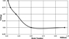 |
Fig. 6 Voltage in terms of the number of elements. |
 |
Fig. 7 Internal fluid parameters assigned. |
 |
Fig. 8 Electrical module selection in (a) Rectangular TEGs, (b) Circular TEGs. |
 |
Fig. 9 Thermoelectric elements selection in (a) Rectangular TEGs, (b) Circular TEGs. |
3.1 Model assumptions and optimization
To simplify the model's solution process, assumptions must be made. The assumptions simplify the simulation, reduce complexity, and provide helpful information. The first assumption is that of a steady state, where velocities, temperatures, and other values remain constant over time, simplifying the analysis because there is no transient state. It was further assumed that there is complete thermal contact throughout all regions and that there is no thermal resistance at the interfaces. An assumption of symmetry exists, as the system is symmetric in both space and thermal distribution. Half of the system will be modeled, and the resulting solutions will be mirrored to approximate the entire system, as shown in Figure 10. This will conserve computation while maintaining the necessary level of accuracy. The fluid is treated as incompressible and follows ideal flow behavior, neglecting turbulence, gravity, buoyancy forces, and other complex flow effects. Also, radiation heat transfer was neglected because it's insignificant compared to conduction and convection, which are valid for minor temperature differences and an insulated system.
In this model, it is necessary to optimize the external connector for maximum power output. The maximum power transfer occurs when the external resistance equals the internal resistance of the system. For the case to reach this optimal condition, the resistivity of the external connector must be tuned and adjusted accordingly. If not, it results in inefficient power transfer, leading to energy losses or reduced system performance. The optimization will consider design parameters, environmental conditions, and material properties that may influence the connector's resistance. Other considerations to be investigated include temperature changes, wear and tear, and connector degradation over time to achieve long-term stability and reliability. Equations (11) and (12) are used in the optimization process to obtain the optimal output power.
 (11)
(11)
 (12)
(12)
where ρ is the resistivity of the connector, V is the voltage, I is the current, A is the cross-sectional area, and L is the length of the connector. The first term in equation (11) is used to calculate the internal resistance of the Thermoelectric generator, and the second term is used to calculate the resistance of the external connectors. The resistivity can be adjusted to achieve the optimum power output. During the optimization process, optimal resistivity was determined to be 5.076 × 10⁻⁶ Ω·m. This corresponds to an electrical conductivity of 197,000 S/m; This value is the optimum for maximum power efficiency of the system.
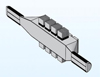 |
Fig. 10 Symmetric assumption. |
3.2 Numerical model validation
The COMSOL Multiphysics model developed in this study is validated against the annular TEG system reported by Zhou et al. [25] to assess its accuracy in predicting system performance. The validation is carried out using identical coolant flow velocities (1.0–5.0 m/s) and heat source temperatures (350 °C and 550 °C), with comparisons based on pressure drop and the temperature difference across the TEG module (ΔT). The results, summarized in Table 1, indicate good agreement between the present model and the reference data. Predicted pressure drops closely match those reported by Zhou et al. [25], with percentage errors remaining below 5.2% over the investigated flow range and typically within 1–3%.
The present model predicts slightly lower temperature differences than those reported in Zhou et al. [25], with errors increasing from 1.7% at the lowest coolant velocity to 2.9% at the highest. These differences are attributed to variations in thermal boundary conditions and in the implementation details of the material properties. The smooth, systematic variation of the temperature error, together with the strong agreement observed in the pressure drop, supports the consistency of the coupled thermal–electrical–fluid simulation framework. Overall, the validation results indicate that the numerical model provides a reliable basis for evaluating the performance of the hybrid annular–rectangular TEG system under different operating conditions.
4 Results and discussions
The section will present the results for the four parameters selected and their influence on the output, power, and efficiency. The parameters investigated include changes in exhaust gas temperature, mass flow rate, ambient air temperature, and velocity. The output power results will provide insight into the system's behavior and performance, highlighting the influence of each parameter. Power output was one of the primary parameters used to confirm the results obtained with the Engineering Equation Solver (EES) and COMSOL. To make a comprehensive comparison, five temperatures between 350 °C and 550 °C are examined, allowing us to assess TEG performance under varying heat conditions. It also provided helpful information on the effects of temperature on power output. Figure 11 shows the variation in TEG power output compared to the EES and COMSOL outputs. The slight variation is attributed to assumptions in the equations, modeling methods, or numerical methods used in each program. Despite the subtle differences between the programs, both show a consistent trend in output power. This serves to validate the results and provides a solid base for further TEG performance analysis and optimization. The percentage difference of results measured by EES and COMSOL has been shown. The maximum error occurs at 550 °C, with a value of 6.95%, which is insignificant; however, it provides validation of the fundamental limitations or differences in the simulation models used in both applications. The comparison remains a valuable assessment of TEG performance, and the error is reasonable for practical use.
The temperature of the entire model varies when interactions with the ambient air in the system are included. As heat continues to be exchanged with the surrounding ambient air, the model will experience temperature variations across different positions. The variations are based on several parameters, including heat-exchange efficiency, airflow, and material thermal conductivity. The temperature distribution across the system on the hot side of the ceramic provides a representation of how temperature behaves differently at spatially distinct positions and how the overall model performance is impacted. Figure 12 illustrates the temperature gradient across the hot side ceramic of the rectangular and circular TEGs.
Understanding the temperature gradient across these different TEG configurations reveals how the model's shape or design can influence heat transfer and thermal performance. Table 2 shows the average temperature distribution over the rectangular and circular TEGs.
The exhaust gas temperature varies with engine load, which directly affects the temperature gradient along the TEGs, leading to fluctuations in power output. Any increase in the temperature gradient typically increases power generation; conversely, a decrease in the temperature gradient reduces the system's efficiency. As observed in Figure 13a, an increase in the sing exhaust increases the gas temperature, while all other parameters are held at their held values. The ambient air temperature was maintained at 25 °C, the wind speed at 80 km/h, and the exhaust gas mass flow rate at 20 g/s. Results indicate a positive correlation between exhaust gas temperature and power output. The maximum output power observed was 218.84 W with an exhaust gas temperature of 550 °C.
In comparison, the minimum power output observed was 81.37 W at 350 °C, with exhaust gas temperatures increasing. As exhaust gas temperatures rise, the system's efficiency and power production increase. This is crucial for performance optimization in practical applications. As shown in Figure 13b, the efficiency of the TEGs also increases with rising exhaust gas temperature. The thermoelectric efficiency is enhanced because of the temperature difference between the cold and hot sides of the TEG. The minimum efficiency rate of 5% was determined to occur at an exhaust gas temperature of 350 °C. On the contrary, the maximum efficiency of 6.8% was achieved at an exhaust gas temperature of 550 °C. These findings demonstrate that higher exhaust gas temperatures increase the driving force of heat transfer, thereby improving the efficiency of thermal energy conversion into electrical power. It's very important to strike a balance between temperature and system sustainability, as material constraints and potential losses can affect efficiency.
Ambient air temperature plays a significant role in cooling the cold side of the TEG and is strongly influenced by weather conditions. The cooling effect directly affects the temperature gradient across the TEG, which, in turn, affects power generation. The lower the ambient air temperature, the more effective the cooling of the cold side, and thus the temperature differential between the cold and hot sides of the TEG will be greater, resulting in higher power output. The cooling effect typically diminishes as ambient air temperature increases, resulting in a smaller temperature differential and reduced power generation. Therefore, the performance of the TEG system can be significantly affected by weather conditions. As shown in Figure 14a, the highest power output occurs at the lowest ambient air temperature, and then decreases with increasing ambient air temperature. Exhaust gas temperature was held constant at a value of 450 °C, wind speed at 80 km/h, and exhaust gas mass flow rate at 20 g/s. From the Fig., the maximum power output was 153 W at an ambient air temperature of 5 °C, and the minimum was 129.33 W. The variation in power output is relatively minor, with a change of 23.67 W between the minimum and maximum values. Figure 14b shows that the TEG system's efficiency decreases with increasing ambient air temperature. This is due to the rise in the cold-side temperature, which reduces the temperature difference across the TEG and lowers the system's overall performance. As shown in Figure 14, the maximum efficiency of 6.3% occurs at an ambient air temperature of 5 °C, where the cold side is noticeably colder, resulting in the largest temperature difference between the hot and cold sides of the TEG. The minimum efficiency of 5.3% is at the higher ambient air temperature of 45 °C. As the ambient temperature increases, the ability to maintain a large temperature difference between the hot exhaust gases and the cold side of the TEG decreases, reducing the energy conversion efficiency.
The speed of an automotive vehicle depends on road conditions, whether on a highway or an internal road, and this significantly influences the pTEG's performance. Driving at higher, more consistent speeds, the TEG system would perform better due to the increased heat generated by the engine. On interior streets, vehicle speeds are generally slower and less consistent, making the TEG's performance less predictable due to lower thermal energy. As shown in Figure 15a, the power output increases with increasing ambient air velocity. This is because the heat transfer rate at the cold side is better with increased velocity, causing the cold-side temperature to decrease. The reduction increases the temperature difference, thereby improving power output. Other parameters remained constant, with an exhaust gas temperature of 450 °C, an ambient air temperature of 25 °C, and an exhaust gas mass flow rate of 20 g/s. The maximum power of 222.81W was achieved when the vehicle velocity reached 120 km/h, and the lowest power of 93.28W was achieved at a vehicle velocity of 40 km/h. Figure 15b shows that the efficiency of the TEG system increases with ambient air speed because the larger heat transfer rate associated with increased air speed lowers the temperature of the cold side. As a result, the temperature difference across the hot and cold sides of the TEG is enhanced, thereby increasing efficiency. A maximum efficiency of 9.2% can be achieved at a velocity of 120 km/h for ambient air, resulting in improved heat dissipation on the cold side with a maximum temperature difference. It was also observed that the lowest efficiency of 3.8% is achieved at a velocity of 40 km/h.
Exhaust gas mass flow rates may vary with engine load, which directly affects the TEG system's performance. If the engine load changes, the exhaust gas flow rate can increase or decrease, altering the thermal energy available for conversion into power. Therefore, the system's performance needs to be assessed under load conditions, as these may affect its efficiency and overall output. As the exhaust gas mass flow rate increases, the TEG system's power output also increases, as shown in Figure 16. This is because the greater exhaust gas volume available for heat transfer enhances the thermal energy input to the system. The exhaust gas temperature was maintained at 450 °C, the ambient air temperature at 25 °C, and the ambient air velocity at 80 km/h. Figure 16a shows that the maximum power output of 192.06 W is achieved at a mass flow rate of 30 g/s, and the minimum power output of 67.53 W is achieved at a mass flow rate of 10 g/s. This trend highlights the significance of the exhaust gas flow rate to the performance of the TEG system, where a higher flow rate yields greater thermal energy, resulting in increased power generation. Figure 16b shows that the TEG system's efficiency initially increases with increasing exhaust gas mass flow rate, reaching a peak at 16 g/s. After that point, the efficiency begins to decline because the exhaust gases maintain a significant temperature difference between the hot and cold sides of the TEG at low mass flow rates. As the mass flow rate increases, the exhaust gases will not have enough time to transfer heat to the TEG before leaving the system, decreasing the temperature gradient and leading to a corresponding drop in efficiency. Where the rate of power rise does not keep up with the rate of increase in thermal input, even while raising the exhaust gas mass flow rate enhances the system's total thermal energy input and, consequently, its absolute power output. The temperature gradient (ΔT) across the thermoelectric elements is reduced, and effective heat absorption is limited at higher flow rates due to the shorter contact time between the exhaust gas and the TEG surface. As a result, even when overall power increases, conversion efficiency, which is the ratio of electrical power output to thermal energy input, declines. The highest efficiency of 5.9% occurs at a mass flow rate of 15 g/s, and the lowest efficiency of 5.3% occurs at a mass flow rate of 30 g/s. The results in Figure 16 indicate an optimal mass flow rate for maximum efficiency, beyond which the system's performance may be compromised.
Any modification to the exhaust system will increase the pressure drop, which negatively impacts the engine's performance. A higher pressure drop increases the work the engine does by forcing exhaust gases out, which can lower both fuel efficiency and overall power output. Adding heat sinks results in a slight increase in resistance to exhaust flow, but the effect on engine power and fuel economy is minimal. The primary function of the heat sinks is to enhance heat transfer and optimize TEG operation, thereby efficiently converting thermal energy into electrical power. The pressure drops with and without the heat sinks are compared to illustrate how these additions affect the exhaust flow and engine performance. Optimizing the exhaust system is crucial to achieving an optimal balance between thermal management and engine performance. Figure 17 shows the pressure drop difference in terms of mass flow rate across the model with and without heat sinks. The maximum pressure drops with and without heat sinks occurred at approximately 2.79 kPa and 2.505 kPa, respectively. The difference in pressure drop was minimal in magnitude. The slight increase in pressure drop caused by the heat sinks will have a minimal influence on the engine's overall performance. Figure 18 shows that the pumping power loss due to pressure drop is very high, with the largest value occurring at a mass flow rate of 30 g/s, reaching 17.63 W. The average pumping power loss is 4.67 W, indicating that the pressure loss has a negligible impact on overall system performance.
Table 3 presents the results of the TEG performance model at the optimal operating conditions, which were achieved at an exhaust gas temperature of 550 °C, a mass flow rate of 30 g/s, an ambient air velocity of 120 km/h, and an ambient temperature of 5 °C. A maximum power of 559.3 W was achieved with an efficiency of 11.7%, the maximum possible under optimum conditions. This investigation highlights the substantial temperature difference between the exhaust gases and the ambient air, a factor that is critical to achieving the highest possible thermoelectric generation. The mass flow rate must be reduced to 16 g/s to achieve maximum efficiency; however, this considered increase of 12.3% causes the power output to drop to 314.7 W.
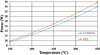 |
Fig. 11 Variation in TEG power output between EES and COMSOL. |
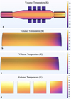 |
Fig. 12 Temperature Distribution on (a) TEG model, (b) First Circular TEG, (c) Last Circular TEG, (d) Rectangular TEGs (Upper Side). |
Average Temperature distribution on TEGs.
 |
Fig. 13 TEGs model (a) Power and (b) Efficiency at different exhaust gas temperatures. |
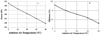 |
Fig. 14 TEGs model (a) Power and (b) Efficiency at different ambient air temperatures. |
 |
Fig. 15 TEGs model (a) Power and (b) Efficiency at different ambient air velocities. |
 |
Fig. 16 TEGs model (a) Power and (b) Efficiency at different mass flow rates. |
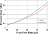 |
Fig. 17 Pressure drop of the model with and without heatsinks. |
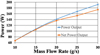 |
Fig. 18 Pumping power losses of the model. |
TEG performance under optimal conditions.
5 Conclusion
This paper presents the development and numerical evaluation of a hybrid annular–rectangular thermoelectric generator (TEG) system integrated with heat sink modules for air-cooled automotive exhaust waste-heat recovery. By combining circular and rectangular thermoelectric modules, the proposed configuration improves heat absorption and dissipation, thereby enhancing thermal and electrical performance across a range of operating conditions. Numerical simulations show that the system achieves a maximum conversion efficiency of 12.3%, corresponding to a power output of 314.7 W, under optimal conditions defined by an exhaust temperature of 550 °C, an exhaust mass flow rate of 16 g/s, a vehicle speed of 120 km/h, and an ambient temperature of 5 °C.
When the system is operated at a higher exhaust mass flow rate of 30 g/s, the electrical power output increases to 559.3 W, while the conversion efficiency decreases slightly to 11.7%. Under representative automotive operating conditions (450 °C exhaust temperature, 20 g/s mass flow rate, 25 °C ambient temperature, and a vehicle speed of 80 km/h), the system delivers 141 W of electrical power with a conversion efficiency of 5.8%, demonstrating its relevance for practical automotive applications.
The results indicate that system performance is strongly governed by exhaust gas temperature and mass flow rate, with conversion efficiency declining beyond an optimal mass flow rate of 16 g/s. The integration of air-cooled heat sinks provides effective thermal management while maintaining a negligible increase in exhaust backpressure, supporting the feasibility of the proposed air-cooled TEG configuration. These results establish a numerical performance baseline for hybrid-geometry TEG systems. Future work will focus on experimental validation, material optimization for higher-temperature operation, and transient analysis under dynamic driving conditions to further bridge the gap between simulation-based design and practical in-vehicle integration.
Acknowledgments
The authors would like to express their sincere gratitude to the University of Jeddah for its support of this research. The authors also appreciate the valuable insights and suggestions provided by colleagues in the Department of Mechanical and Materials Engineering.
Funding
This research received no external funding.
Conflicts of interest
The authors declare no conflicts of interest related to the publication of this article.
Data availability statement
No new data were created or analyzed in this study. Data sharing is not applicable to this article.
Author contribution statement
Conceptualization, S. Ghazali and A. Alkotami.; methodology, A. Alkotami.; software, S. Ghazali.; writing original draft preparation, S. Ghazali and A. Alkotami.; writing review and editing, S. Ghazali and A. Alkotami. All authors have read and agreed to the published version of the manuscript.
References
- R.Y. Dahham, H. Wei, J. Pan, Improving thermal efficiency of internal combustion engines: recent progress and remaining challenges, Energies (Basel) 15, 6222 (2022) [Google Scholar]
- S. Twaha, J. Zhu, Y. Yan, B. Li, A comprehensive review of thermoelectric technology: materials, applications, modelling and performance improvement, Renew. Sustain. Energy Rev. 65, 698–726 (2016) [Google Scholar]
- I. Johnson, W.T. Choate, A. Davidson, Waste Heat Recovery, Technology and Opportunities in US Industry, Laurel, MD, United States, 2008. https://doi.org/10.2172/1218716 [Google Scholar]
- R. Quan, C. Zhang, Q. Chen, Y. Chen, W. He, Performance interaction assessment of automobile exhaust thermoelectric generator and engine under different operating conditions, Appl. Therm. Eng. 216, 119055 (2022) [Google Scholar]
- H. Lee, Thermoelectrics: Design and Materials, John Wiley & Sons, 2025 [Google Scholar]
- Melcor, Thermoelectric application, in: Thermoelectric Handbook, Catalogs by Melcor, 2008, pp. 1–3 [Google Scholar]
- V. Vaidyanathan, Thermoelectric Generator: Principle, Mechanism and Materials, 2023, https://www.scienceabc.com/innovation/thermoelectric-generator-principle-mechanism-materials.html [Google Scholar]
- N. Zulkepli, J. Yunas, M.A. Mohamed, A.A. Hamzah, Review of thermoelectric generators at low operating temperatures: working principles and materials, Micromachines (Basel) 12, 734 (2021) [Google Scholar]
- Y.T. Wang, W. Liu, A.W. Fan, P. Li, Performance comparison between series-connected and parallel-connected thermoelectric generator systems, Appl. Mech. Mater. 325, 327–331 (2013) [Google Scholar]
- H. Jouhara, N. Khordehgah, S. Almahmoud, D. Delpech, A. Chauhan, Thermoelectric generator (TEG) technologies and applications, Int. J. Thermofluids 9, 100063 (2021) [Google Scholar]
- J. Liu, Q. Liu, S. Lin, M.Y. Leung, Y. Ma, X. Tao, Wearable thermoelectric generators: materials, structures, fabrications, and applications, Phys. Status Solidi RRL 17, 2200502 (2023) [Google Scholar]
- G. Li, X. Zhao, Z. Du, A. Wang, A review on micro combustion powered thermoelectric generator: history, state‐of‐the‐art and challenges to commercialization, Renew. Sustain. Energy Rev. 207 114897 115851 (2025). https://doi.org/10.1016/j.rser.2024.114897 [Google Scholar]
- P. Saini, J.D. Osorio, Review on phase change materials and thermoelectric generators for ocean thermal gradient applications, Renew. Sustain. Energy Rev. 219 (2025). https://doi.org/10.1016/j.rser.2025.115851 [Google Scholar]
- U. Sajjad, A. Ali, H.M. Ali, K. Hamid, A review on machine learning driven next generation thermoelectric generators, Energy Convers. Manag. X 27, 101092 (2025) [Google Scholar]
- M. Ridwan, M. Gasulla, F. Reverter, Principle and applications of thermoelectric generators: a review, Sensors 25, 2484 (2025) [Google Scholar]
- S. Yang, H. Chen, D. Luo, A comprehensive review of thermoelectric generators from micropower supply to kilowatt system, Green Energy Fuel Res. 2, 93–108 (2025) [Google Scholar]
- D. Champier, Thermoelectric generators: a review of applications, Energy Convers. Manag. 140, 167–181 (2017) [Google Scholar]
- V.T.N. Tien, V.N.D. Nguyen, Novel designs of thermoelectric generator for automotive waste heat recovery: a review, AIMS Energy 10, 922–942 (2022) [Google Scholar]
- N. Jaziri, A. Boughamoura, J. Müller, A comprehensive review of thermoelectric generators: technologies and common applications, Energy Rep. 6, 264–287 (2020) [Google Scholar]
- S. Ezzitouni, P. Fernández‑Yáñez, L. Sánchez, O. Armas, Global energy balance in a diesel engine with a thermoelectric generator, Appl. Energy (2020). https://doi.org/10.1016/j.apenergy.2020.115139 [Google Scholar]
- P. Fernández‑Yáñez, V. Romero, O. Armas, G. Cerretti, Thermal management of thermoelectric generators for waste energy recovery, Appl. Therm. Eng. 196, 117291 (2021) [Google Scholar]
- M. Hyland, H. Hunter, J. Liu, E. Veety, D. Vashaee, Wearable thermoelectric generators for human body heat harvesting, Appl. Energy 182, 518–524 (2016) [Google Scholar]
- J. Chen, L. Zuo, Y. Wu, J. Klein, Modeling, experiments and optimization of an on-pipe thermoelectric generator, Energy Convers. Manag. 122, 298–309 (2016) [Google Scholar]
- W.H. Chen, W.C. Bai, D. Luo, A.A. Bandala, X.D. Wang, A.T. Hoang, Optimization of material properties and performance of flexible thermoelectric generators with/without graphene, Energy Convers. Manag. X 24, 100741 (2024) [Google Scholar]
- W. Zhou, X. Tang, J. Zhu, Design and optimal coolant flow rate analysis of an annular water-cooled automotive exhaust-based thermoelectric generator, Case Stud. Therm. Eng. 56, 104256 (2024) [Google Scholar]
- B. Huang, Z.-G. Shen, Performance assessment of annular thermoelectric generators for automobile exhaust waste heat recovery, Energy 246, 123375 (2022) [Google Scholar]
- S. Bhakta, B. Kundu, A review of thermoelectric generators in automobile waste heat recovery systems for improving energy utilization, Energies 17, 1016 (2024) [Google Scholar]
- D. Luo, H. Zhang, J. Cao, Y. Yan, B. Cao, Numerical investigation and optimization of a hexagonal thermoelectric generator with diverging fins for exhaust waste heat recovery, Energy 301, 131756 (2024) [Google Scholar]
- L. Achiței, G. Achiței, D. Sachelarie, A. Popescu, Thermoelectric generators in automotive applications: a comprehensive review of concepts, materials, and integration strategies, Bulletin of the Polytechnic Institute of Iași, Machine Constructions Section 71, 103–114 (2025) [Google Scholar]
- S. Singh, S. K. Rathore et al., Experimental and numerical analysis of fin-enhanced annular thermoelectric generators for waste heat recovery in internal combustion engines, J. Clean. Prod. 442, 140982 (2025) [Google Scholar]
- L. Chen, T. Wang, X. Zhang, Experimental validation of multi-parameter optimization for automotive exhaust thermoelectric harvesters under ambient airflow conditions, Int. J. Energy Res. 50, 112–125 (2026) [Google Scholar]
- D.O. Esen, H.S. Soyhan, M. Canakci, Exploring thermoelectric generation of electrical energy from exhaust gas heat: an experimental study, Therm. Sci. 29, 3875–3885 (2025). [Google Scholar]
- Z. Li, G. Ma, Y. Li, S. Mao, S. Liu, C. Wu, Heat pipe-enhanced two-stage thermoelectric harvester based on phase change material, Energy 292, 130545 (2024) [Google Scholar]
- R. Sukarno, Z.I. Moreno et al., Experimental investigation of a thermoelectric generator assisted with heat pipe sinks for pickup car exhaust waste heat recovery, Commun. Sci. Technol. 10, 106–116 (2025) [Google Scholar]
- D. Kashid, S. Barhatte, D. Ghodake, Thermoelectric power generation using waste-heat energy from internal combustion engine, Int. J. Curr. Eng. Technol. 4, 7–15 (2011). https://doi.org/10.14741/Ijcet/22774106/spl.4.2016.2 [Google Scholar]
Cite this article as: S. Ghazali, A. Alkotami, Evaluation of thermoelectric generators for automotive waste heat recovery, Mechanics & Industry 27, 33 (2026), https://doi.org/10.1051/meca/2026030
All Tables
All Figures
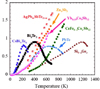 |
Fig. 1 Fig. of merit for multiple materials [26]. |
| In the text | |
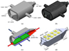 |
Fig. 2 Annular exhaust-based TEG system used by Zhou et al. [25]. |
| In the text | |
|
Fig. 3 (a) Rectangular TEG, (b) Internal rectangular TEG's Components, (c) Circular TEG, (d) Internal circular TEG's Components. |
| In the text | |
|
Fig. 4 (a) Rectangular heat sink, (b) Circular heat sink. |
| In the text | |
|
Fig. 5 (a) Exhaust Pipe, (b) Final Model. |
| In the text | |
|
Fig. 6 Voltage in terms of the number of elements. |
| In the text | |
|
Fig. 7 Internal fluid parameters assigned. |
| In the text | |
|
Fig. 8 Electrical module selection in (a) Rectangular TEGs, (b) Circular TEGs. |
| In the text | |
|
Fig. 9 Thermoelectric elements selection in (a) Rectangular TEGs, (b) Circular TEGs. |
| In the text | |
|
Fig. 10 Symmetric assumption. |
| In the text | |
|
Fig. 11 Variation in TEG power output between EES and COMSOL. |
| In the text | |
|
Fig. 12 Temperature Distribution on (a) TEG model, (b) First Circular TEG, (c) Last Circular TEG, (d) Rectangular TEGs (Upper Side). |
| In the text | |
|
Fig. 13 TEGs model (a) Power and (b) Efficiency at different exhaust gas temperatures. |
| In the text | |
|
Fig. 14 TEGs model (a) Power and (b) Efficiency at different ambient air temperatures. |
| In the text | |
|
Fig. 15 TEGs model (a) Power and (b) Efficiency at different ambient air velocities. |
| In the text | |
|
Fig. 16 TEGs model (a) Power and (b) Efficiency at different mass flow rates. |
| In the text | |
|
Fig. 17 Pressure drop of the model with and without heatsinks. |
| In the text | |
|
Fig. 18 Pumping power losses of the model. |
| In the text | |
Current usage metrics show cumulative count of Article Views (full-text article views including HTML views, PDF and ePub downloads, according to the available data) and Abstracts Views on Vision4Press platform.
Data correspond to usage on the plateform after 2015. The current usage metrics is available 48-96 hours after online publication and is updated daily on week days.
Initial download of the metrics may take a while.