| Issue |
Mechanics & Industry
Volume 27, 2026
Artificial Intelligence in Mechanical Manufacturing: From Machine Learning to Generative Pre-trained Transformer
|
|
|---|---|---|
| Article Number | 10 | |
| Number of page(s) | 13 | |
| DOI | https://doi.org/10.1051/meca/2026004 | |
| Published online | 10 March 2026 | |
Original Article
Collaborative optimization system for in dustrial intelligent manufacturing and digital electromechanical systems based on artificial intelligence technology
College of Electronical and Information Engineering, Tianjin Vocational Institute, Tianjin 300410, PR China
* e-mail: This email address is being protected from spambots. You need JavaScript enabled to view it.
Received:
12
August
2025
Accepted:
26
January
2026
Abstract
A collaborative optimization system for industrial intelligent manufacturing and digital electromechanical systems based on artificial intelligence (AI) technology achieves real-time monitoring and smart management of the production process through data collection, analysis, and processing and digitizes modeling and simulation to achieve collaborative optimization and intelligent control. Analyzing the components and control modules, power modules, and system parameters under the electromechanical system, the traditional proportional–integral–derivative (PID) control and fuzzy neural network PID control methods were compared. The results showed that under constant load, the maximum errors between the tracking speed and the preset speed were 0.3 m/s and 0.2 m/s, respectively, when the PID control speed curve speed was 0–40 ms and 40–100 ms. When the speed curve of fuzzy neural network PID control under constant load was 0–40 ms and 40–100 ms, the maximum errors between the tracking speed and the preset speed were 0.2 m/s and 0.2 m/s, respectively. According to the results, the tracking control effect of fuzzy neural network PID control was superior.
Key words: Artistic intelligence / industrial intelligence / cooperative optimization system / digital electromechanical system / fuzzy neural network
© S. Liu and Z. Li, Published by EDP Sciences 2026
 This is an Open Access article distributed under the terms of the Creative Commons Attribution License (https://creativecommons.org/licenses/by/4.0), which permits unrestricted use, distribution, and reproduction in any medium, provided the original work is properly cited.
1 Introduction
With the raproportional–integral–derivative development of modern industry, the deep integration of digital intelligent control technology and mechatronics systems has become a key driving force for improving production efficiency and product safety. The wave of Industry 4.0 and intelligent manufacturing has promoted real-time monitoring and intelligent management of production processes, meeting the demands of modern manufacturing for customization, efficiency, and low carbon emissions. The rapid proportional–integral–derivative development of technologies such as artificial intelligence, big data, and cloud computing has brought revolutionary changes to industrial automation. For example, in the field of electromechanical systems such as high-voltage switch control, the application of intelligent technologies is becoming a research hotspot. However, although these technologies have significantly optimized operational processes, many challenges remain in practical applications, such as insufficient control precision, poor system adaptability, and difficulties in parameter co-optimization. These problems restrict the further promotion of intelligent manufacturing in industry. Therefore, developing an intelligent control method capable of achieving co-optimization of electromechanical systems is of significant engineering importance and urgency.
The motivation for this research stems from addressing the tracking control accuracy problem of digital electromechanical systems (DEMs) under dynamic loads in intelligent industrial manufacturing. Traditional control methods, such as proportional–integral–derivative control, are stable under constant loads but tend to exhibit response lag and increased errors under variable loads, leading to decreased production efficiency and shortened equipment lifespan. Especially in typical applications such as high-voltage switches and robot manipulators, achieving fast and accurate speed tracking has become a key engineering challenge. This paper aims to design a collaborative optimization system by introducing artificial intelligence technology to reduce speed tracking errors and improve the system’s robustness and adaptability.
This research focuses on improving the control parameters of digital electromechanical systems, specifically reducing the speed tracking error from 0.3 m/s in traditional proportional–integral–derivative control to below 0.2 m/s using a fuzzy neural network proportional–integral–derivative control algorithm, and achieving stability with error fluctuations of less than ±0.02 m/s under variable load conditions. Simultaneously, this research aims to improve overall equipment efficiency and reduce unplanned downtime, thereby verifying the system’s effectiveness in real-world industrial scenarios. The innovation lies in combining digital twin technology with fuzzy neural network proportional–integral–derivative control to construct a “parameter-coordinated” optimization framework. This framework not only achieves parameter linkage across levels (from control equipment to workstations) and throughout the entire lifecycle (development and operation/maintenance) but also enhances the joint design of control algorithms and mechanical structures through a multisource data-driven mechanism. This innovation breaks through the limitations of traditional control and provides a scalable solution for intelligent manufacturing in industry.
This research area encompasses industrial automation, mechatronics, and artificial intelligence applications. Specific research objects include typical digital electromechanical systems such as crank-slider mechanisms, which consist of mechanical components and control modules, such as DC servo motors and flexible connecting rods. Through multibody dynamics modeling and real-time simulation, this study treats the EEMS as a whole, optimizing the synergy between its functional modules. To achieve these goals, the research tasks include system architecture design (covering data acquisition, analysis and processing, intelligent management, DEMS, and control system modules), control algorithm development (comparing traditional proportional–integral–derivative with fuzzy neural network proportional–integral–derivative), simulation experiments for verification (testing performance under constant and variable loads), and comprehensive evaluation (such as temperature effects and energy efficiency analysis). These tasks ensure consistency from theory to practice, laying the foundation for subsequent engineering deployment. In summary, this paper proposes an innovative collaborative optimization system by integrating advanced artificial intelligence technologies, aiming to promote the development of intelligent manufacturing in industry. Subsequent chapters will elaborate on the relevant work, methods, experimental results, and discussion to comprehensively demonstrate the contributions and practicality of this research.
2 Related work
Industrial intelligent manufacturing refers to the use of artificial intelligence, big data, cloud computing, and other technologies to achieve real-time monitoring and smart management of the production process, thereby improving production efficiency and product quality. Ha S proposed a new computational method to optimize the morphological design of robots. He took parameterized robot design and motion plans composed of trajectories of end effectors and optional body trajectories as inputs. The algorithm optimized design parameters, including link length, actuator position, and adjusted motion parameters, such as joint trajectory, actuator input, and contact force. Finally, the morphological framework of the optimized robot was further validated by optimizing the design of two small quadruped robots and testing their performance using hardware implementation [1]. With the development of raproportional–integral–derivative prototyping and mechatronics in recent years, the problems of synchronous design and motion optimization or joint design have become increasingly significant in the field of robotics. Due to computational operability, all existing methods used simplified approximations of robot motion dynamics models. Kwon J has empirically confirmed that any model approximation that was physically inconsistent, i.e., the kinetic model parameters could not accurately reflect the shape of the actual link, could sometimes lead to significant errors in optimization. Then, Kwon J proposed a physically consistent mesh element model that parameterized various link shapes and provided closed-form analysis gradients for mesh deformation. The latter’s characteristic was the key to developing efficient collaborative design optimization algorithms, which could significantly improve numerical convergence and stability. Kwon J’s collaborative design method has been validated through extensive numerical and hardware experiments involving serial and parallel robots for three-dimensional (3D) printing [2]. Shao Y considered that interconnected and autonomous vehicles could bring energy, mobility, and safety benefits to transportation. By using connectivity-based preview traffic information to solve a forward-looking mathematical optimization problem, energy savings could be achieved. However, predicting short-term traffic was challenging, especially in mixed traffic situations where both connected and unconnected vehicles were driving on the road [3]. In the current social environment, artificial intelligence is constantly developing and integrating into various industries. Only by continuously optimizing artificial intelligence algorithms can work efficiency be improved.
With the deepening development of economic globalization and informatization, the manufacturing industry is facing enormous opportunities and challenges. In this context, the collaborative optimization of industrial intelligent manufacturing and digital electromechanical systems has become an important direction for the current development of the manufacturing industry. Faudzi A.A.M. introduced the current applications of microelectromechanical systems in the fields of robotics and industry. Microelectromechanical systems were widely used as actuators or sensors in many aspects of daily life, as well as in automated production lines and industrial applications. The combination of new polymers and composite materials with micro-manufacturing technologies for microprocessing and microassembly has led to significant growth in the application and effectiveness of microelectromechanical system equipment. Microelectromechanical systems have made significant improvements in reducing size and improving reliability, versatility, customized design, and power usage. Faudzi A.A.M. showcased various devices and technologies used in robotics and industrial applications, as well as the use and role of silicon in sensor development. Some future trends and prospects were also discussed [4]. Liu L. proposed an adaptive sensor fault identification mechanism based on a data framework that leverages the dynamic response characteristics of a class of multi-input single-output discrete-time non-modeling systems. It was tested. However, due to the complexity of fault diagnosis, the design and stability analysis of control systems became very difficult. Ultimately, after detecting the fault, the strategy for a class of multi-input, single-output discrete-time model-less systems in the data framework was calculated based on the adaptive sensor fault detection mechanism and optimality criteria of the echo state network. It was then shown that all signals, including tracking errors, were bounded [5]. Mechanical and electrical systems are pervasive. The importance of constructing dynamic equations for coupling electric motors and mechanical systems indicates a new strategy. Tian D. believed that the standard derivation of dynamic equations for purely mechanical systems could be modeled after electromechanical systems. The main reason was that, in electromechanical systems, people had to deal with continuous electromagnetic fields. This field stored electrical and mechanical energy. In a purely mechanical system, conservative mechanical energy was stored as elastic or gravitational energy, and non-conservative terms entered the equation as non-conservative force. This was not achievable in electromagnetic systems. Tian D. demonstrated the correct method for deriving dynamic equations and applied the results of two systems. Both systems consisted of a motor, a coupling mechanism, and a mechanical subsystem [6]. The electromechanical system is composed of multiple functional modules. To improve its performance and efficiency, it is necessary to start with the correlation between each functional module and carry out collaborative optimization of each functional module to ensure effective improvement of its performance.
3 Materials and methods
3.1 Data acquisition module
The data collection module mainly collects parameters such as temperature, pressure, humidity, current, voltage, and others during the production process. The data acquisition module typically uses a sensor or other means to acquire the information and converts it into a digital signal [7]. In the digital signal processing stage, relevant algorithms are used to filter, amplify, and separate the obtained information and output it as standardized data according to specific protocols.
The data collection module achieves real-time, reliable, and efficient data collection. Its primary functions are multi-channel input: the data acquisition module can synchronously read various sensors such as temperature, pressure, humidity, and others; signal processing: using specific algorithms to filter, amplify, and separate signals ensures the accuracy and reliability of the signal; and protocol transformation: The collected data is transformed into standard protocols such as MODBUS and object linking and embedding for process control (OPC).
The data acquisition module has been widely used in many fields, including industrial automatic control. It can collect various sensing information from mechanical devices. Simultaneously, it can also improve product quality and production rate through real-time monitoring and analysis of these data; smart home: By installing data acquisition modules on household appliances and sensors, it is convenient to achieve real-time monitoring of environmental parameters such as temperature, humidity, and air quality; logistics monitoring: through the data collection module, information such as vehicles and goods is collected to track and monitor the entire logistics chain.
The data collection function is one of the most critical data sources for the entire power communication data network gateway system. It obtains configuration and performance data from various professional network management systems and devices, normalizes them, and stores them in the database, providing basic data for the successful implementation of each subsystem’s functions [8]. Figure 1 depicts the data acquisition function architecture.
On this basis, this section elaborates on an information collection method based on usage management. Among them, the main function of the application level is to process information from the collection work, perform appropriate operations on it, and provide users with an interface for the collection work, data processing, and other content. Besides, information transmission technology and big data analysis operations also need collection management [9]. The primary function of the information collection layer is to perform collection agent work and manage the collection adapter. The hierarchical relationship diagram of the data acquisition module is described in Figure 2.
To address multi-protocol compatibility issues within the data acquisition module, the system employs a middleware architecture based on the OPC UA information model. By defining a unified data namespace and semantic mapping table, MODBUS register addresses are mapped to OPC UA nodes. This conversion process is implemented by a lightweight gateway program, supporting millisecond-level data synchronization and ensuring seamless integration and semantic consistency of heterogeneous device data at the acquisition layer.
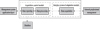 |
Fig. 1 Data collection architecture diagram. |
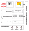 |
Fig. 2 Hierarchy diagram of data collection module |
3.2 Data dissection and processing module
The data analysis and processing module is mainly responsible for data analysis and processing to achieve real-time monitoring and intelligent management.
The primary purpose of data analysis is to assist inspection personnel in managing daily pending and inspected work matters and to quickly locate equipment inspection details by equipment number or a specific time period, as well as statistics on inspection times and the distribution of inspection time [10]. Maintenance and inspection work are the same. The data from dozens of devices is monitored, and if any abnormalities occur, an alarm is initiated or an abnormality report is sent to the supervisor for processing. Based on the number of equipment, a specific time period, and other factors, detailed data on equipment inspections, patrols, repairs, maintenance, and other activities can be quickly queried.
At the management level, the primary purpose of the data analysis and processing module is to obtain the equipment operation overview, equipment status distribution, patrol inspection, and repair and maintenance status in real time; to further optimize them based on data and information visualization; and to propose better planning arrangements or provide strong support for business decision-making [11]. A detailed analysis of the warranty repair situation should be conducted. The repair process and personnel arrangements are optimized, and the plan is repaired through visual reports, improving the efficiency of warranty repair work and reducing unnecessary expenses. The data analysis monitoring interface can be shown in Figure 3.
The steps of data collection and analysis are as follows: First, clarify the data analysis objectives; then, collect relevant information; next, process and organize the collected data to meet the requirements of data analysis and ensure the accuracy and precision of the data; then, use appropriate analysis methods and tools to analyze the collected data, extract useful information, and draw meaningful conclusions; next, present the data in graphical or other forms; and finally, write a data analysis report to summarize and present the entire data analysis process [12].
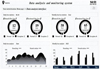 |
Fig. 3 Data analysis monitoring interface. |
3.3 Intelligent management module
The main task of the intelligent management module is to achieve intelligent management of the production process, which includes formulating production plans, scheduling production processes, and repairing production equipment. The goal of production scheduling is ensuring timely delivery and shortening delivery time; strictly implementing planning and strengthening planning guidance; reducing product delivery time and inventory; reducing the adverse effects and losses caused by the smooth progress of the overall production process due to unreasonable production plans; tracking various abnormal phenomena that occur during the production process; collecting and summarizing means of production and statistical data, managing production orders as a whole, and ensuring timely information, centralized data, and accurate data; and maximizing the resource advantages of the enterprise and creating greater value for the enterprise.
Production scheduling is the process of organizing and executing production plans. Production scheduling is based on the production schedule and needs to be completed using production scheduling [13]. Owing to the essence of enterprise production and operation, production planning is an inevitable choice. In modern industrial enterprises, there are many production links and complex cooperative relationships between enterprises. Their production has strong continuity, and the situation between them is also rapidly changing. If a part malfunctions or a specific measure is not completed on time, it may have an impact on the operation of the entire production system [14]. Real-time monitoring of various links is conducted in the production process to understand the operational status of the site and station in a timely manner, taking corresponding response measures in a timely manner. Labor is reasonably allocated according to production needs, and the supply of raw materials, tools, electricity, and transportation is supervised and inspected at factory stations.
The following principles need to be noted during the production scheduling process:
First, there is a principle of having a plan. Production scheduling should be carried out according to the production plan, which is a fundamental principle. Each step of production scheduling is carried out to complete the production plan.
Second, there should be a sense of prevention. The most important task of production scheduling is to implement the production plan in place. Before starting work, potential problems should be anticipated and appropriate measures taken to address them, rather than waiting until problems arise to discuss how to solve them. This may affect the continuous progress of production and waste time.
Third, there should be a principle of timeliness. In the production process, if there are issues such as wire breakage that can affect production progress, the workforce should be immediately dispatched to solve them.
Fourth, there should be a principle of unification. In all aspects of production scheduling, unity in thinking and action should be achieved. To implement the principles of centralization and unity, it is necessary to ensure that each production department schedules according to the instructions and production tasks issued by the leaders and keeps pace with the others, rather than acting independently.
Fifth, there should be a principle of substantiation. Production scheduling should be based on reality, go deep into the production line, and timely and accurately understand the production situation, analyzing and studying it to provide a reference for production scheduling and prevent arbitrary commands.
Maintenance and upkeep of production equipment: Maintaining the normal working condition of the equipment through conventional methods such as wiping, cleaning, lubrication, and adjustment is called equipment maintenance.
The basic requirements for the maintenance and repair of mechanical equipment include several key aspects. First, the interior of the machine must be clean, with no dirt on sliding surfaces, screws, racks, gearboxes, oil hole plugs, and other parts. All components should be free of oil or gas leaks, and chips, impurities, and dirt around the machine should be removed. Machinery, accessories, and workpieces (products) should be neatly arranged, and pipelines, circuits, and other components should be organized in a timely manner. Regular oil topping up and changes should be carried out, ensuring no dry friction and continuous oil flow. The oil pressure should be normal, the oil level clear, and the oil passage unobstructed. Oil quality must meet the required standards, and oil nozzles, oil cups, and oil carpets should be kept clean. Last, strict adherence to safety operation regulations is essential, and equipment should not be overloaded. All safety protection measures must be complete and reliable, with potential safety risks identified and eliminated promptly.
Broadly speaking, the maintenance and upkeep of mechanical equipment include daily maintenance, regular maintenance, regular inspections, accuracy checks, etc. Besides, it includes the maintenance of mechanical equipment’s lubrication and cooling systems. Daily equipment maintenance is the basic work of equipment maintenance, so it must be institutionalized and standardized [15]. In the routine maintenance work of equipment, it is necessary to establish a work budget and a material consumption budget and evaluate them based on the budget. The daily maintenance budget for equipment should be included in the evaluation of the workshop contracting system. Regular equipment inspection is a planned preventive inspection that requires not only human perception but also some inspection tools and instruments. It is carried out according to the regular inspection card, also known as regular spot checks. Mechanical equipment also needs to undergo accuracy checks to determine its true accuracy [16]. The maintenance work of equipment must follow maintenance procedures, which are a requirement and standard for daily maintenance of equipment.
The so-called block maintenance of equipment refers to the establishment of a complete maintenance system for a specific part or function of the equipment in a specific production area. The maintenance workers are a component of this system, and their role is to maintain the equipment. In this production area, maintenance workers should work together with production operators to carry out daily maintenance, patrol inspections, regular maintenance, planned repairs, and troubleshooting [17]. Simultaneously, indicators such as equipment integrity rate and failure shutdown rate within the management area should be assessed.
In an automotive parts manufacturing workshop, the seven production scheduling principles proposed in this article (such as prioritizing equipment status, balancing energy consumption, and weighting task urgency) were embedded in their MES system. The system dynamically adjusted the processing queues of CNC machine tools based on real-time equipment health and order due dates. After implementation, overall equipment effectiveness (OEE) increased by 12.3%, and unplanned downtime decreased by 28%, validating the effectiveness and feasibility of the proposed scheduling strategy in complex production scenarios [18].
In the intelligent management module, this paper further integrates knowledge graph technology to enhance fault diagnosis and maintenance decision-making capabilities. By constructing a domain ontology covering equipment structure, typical failure modes, failure mechanisms, maintenance cases, and expert experience, unstructured maintenance documents and structured operational data are uniformly mapped to the knowledge graph. When the system detects an abnormal signal, the inference engine can quickly identify the potential source of the fault using graph association relationships. Combining the current operating condition of the equipment with historical maintenance records, it generates customized maintenance recommendations that include priority ranking, spare parts requirements, and operating instructions, significantly improving operation and maintenance efficiency and scientific decision-making.
3.4 Digital electromechanical system module
The digital electromechanical system module is mainly responsible for digitizing, modeling, and simulating various parts of the electromechanical system, achieving collaborative optimization and intelligent control of the electromechanical system.
Digital models: Today’s digital technology is constantly changing every industry. In the future, all enterprises can become digital companies, which not only requires them to develop products with digital characteristics but also means transforming the product design, development, manufacturing, and service processes in a digital way and connecting the enterprise’s internal and external environments digitally. Due to the shortening of product lifecycle and the continuous improvement of product customization level, enterprises need to build a collaborative ecological environment with upstream and downstream [19]. This requires enterprises to accelerate product development through digital means, improve the efficiency of development, production, and service, and enhance the openness of the internal and external environment of the enterprise.
This digital transformation is very different from the traditional design and production concepts that have been based on experience for decades. Designers may not need to rely on developing real physical prototypes to validate design concepts, nor do they need to use complex physical experiments to verify or make direct judgments about production bottlenecks through small-scale trial production, let alone go to the site to understand the operational status of products sold to customers. This method is undoubtedly carried out throughout the entire product lifecycle, which can accelerate product development, improve development and production efficiency and economic benefits, and better understand product usage, thereby reducing customer losses [20,21]. It can also accurately provide feedback on customers’ actual usage to the design team, thereby achieving the goal of effective product improvement.
The control system module is mainly responsible for achieving intelligent control of the electromechanical system, including the design of control algorithms, selection of controllers, and adjustment of control parameters. The system works like the human brain, manipulating the body to drink water.
The automatic control system consists of the following components: The function of the detection device is similar to that of the human eye in the above example, and its main function is to obtain feedback information. The function of the controller is similar to that of the brain in the above example, which is largely used to decide how to proceed. The function of the actuator, like that of a human body, is to execute commands issued by the controller in the above example. Control is the goal to be achieved: just like the distance between a human tongue and the water surface, control is the ultimate goal to make machines run automatically.
3.5 Implementation of electromechanical systems
In electromechanical systems, parameter collaboration between components is an essential prerequisite for ensuring their safe and efficient operation. For a long time, there has always been a factor of parameter inconsistency in electromechanical systems. Due to parameter deviations between various components, the equipment cannot operate efficiently. Due to the lack of sufficient personnel and effective optimization methods, parameter problems between multiple components have not been resolved. To maintain the normal operation of the equipment and ensure the normal operation of the electromechanical system, it is necessary to conduct research on the parameter adjustment of each module in the system and summarize corresponding optimization methods to improve the parameter synergy between each module, ameliorating the system’s operational stability and extending the system’s lifespan.
Mechanical and electrical equipment consists of two main parts: the mechanical system and the control system. These two systems determine the mechanical and electrical device parameters, and, correspondingly, the system parameters also determine the mechanical and control performance of electromechanical equipment. Therefore, when designing electromechanical integration, the parameters of each functional module should be comprehensively considered, coordinated, and optimized to improve the overall performance of the product.
To achieve coordination and optimization among multiple modules, models between multiple modules should be established first. Based on the theory of multibody dynamics, the design of electromechanical equipment is carried out. This project uses the theory of multibody dynamics to model and simulate it in control software. Among them, the control module is a relatively complex link that contains many instructions and is challenging to optimize. Usually, there are tens to hundreds of iterations that require designers to consider how to reduce computational time, and the most common method is the “critical mode” method.
This paper introduces digital twin technology to construct a virtual mapping. This mapping is driven by a high-fidelity multibody dynamics model and real-time sensor data, using the OPC UA protocol to establish a bidirectional data channel between the physical entity and the virtual model. Physical operating status (such as posture, vibration, and temperature) is pre-processed by an edge computing unit and uploaded to the cloud-based twin. The twin then performs state prediction and performance evaluation using historical data and online simulations and feeds back optimization instructions to the physical controller. This forms a closed-loop interactive mechanism of “perception-analysis-decision-execution”, supporting the full lifecycle management of the system.
Data collection and real-time control of various parameters of the control system and mechanical system are realized. The parameter acquisition module mainly collects parameters related to audio signals, including audio signal parameters, module operating parameters, power parameters, and environmental and security detection system parameters. Among them, the module data manager uses a high-speed digital processor based on the reduced instruction set computer (RISC) architecture, a pipeline-based data processing system. This design feature allows for extremely high system parameter synergy and the ability to process multiple signals simultaneously.
Within the mechanical system, there can be built-in interfaces such as Universal Serial Bus (USB), Serial Peripheral Interface (SPI), Inter-Integrated Circuit (IIC), etc. These interfaces can improve the execution efficiency of data collection and facilitate parameter collection. The control chip of the control system can be embedded with complex operating systems such as Windows Embedded Compact (Wince) and GNU/Linux (Linux), which can facilitate user management and operation of different events, achieving real-time processing of multiple tasks.
The crank slider belongs to the mechanical structure of the electromechanical system. Its input is the angular velocity of the crank rotation, and its output is the torque applied to the crank. The external force applied to the slider and the direction of motion are opposite. The crank and slider are rigid parts, while the connecting rod is a flexible part. On this basis, according to the characteristics of equipment materials, such as elastic modulus, Poisson’s ratio, and density, the three-dimensional solid element with 20 nodes is used for its discretization. As a result, the collaborative optimization between each control module is realized. At the interface between the connecting rod and the external components of the electromechanical system, there is a bearing that carries all the forces and also supports the load on the moving pair. Connecting the DC servo motor to the crankshaft can enable the system to obtain power and complete the work. Therefore,
 (1)
(1)
Among them,  is used to represent the armature input voltage of the motor; KT is used to represent the torque coefficient; La is used to represent the armature inductance; Ra is used to represent the armature resistance; J is used to represent the Moment of inertia of the motor; TL is used to represent the torque exerted by the servo motor on the crank during movement; and θ(S) is used to represent the motor output angle. On this basis, the established mathematical equation is used to calculate the output angle of the motor, complete three-dimensional simulation calculations, and ultimately achieve optimization of the control module parameters of the motor.
When conducting coordinated optimization, the parameter requirements of the multi-body dynamics model and the control module are the same. If there are differences in the parameters between them, it leads to different loading histories of the flexible components. The ultimate result is that after the topology optimization is completed, the shape of the flexible components of the electromechanical equipment differs, and the service life of the equipment is shortened. Due to inconsistent parameter requirements between the dynamic model of a multi-body system and the control module, the system’s stress history differs, leading to structural deformation and reducing its service life. Therefore, in the design of the designer, attention should be paid to the balance between the system’s dynamic modeling and the control system’s parameters. First, differential evolution is used to select the initial population randomly from the electromechanical system so that the system can be consistent in all parameter spaces. Among them, i is the ith person, with X as the random variable. Formula (2) is obtained from the output rotation angle of the motor:
 (2)
(2)
In this formula,  , which is a random variable. NP individuals
  are generated during the initialization process. First, it is imported into the software to establish a mechanical model of the electromechanical system. The algorithm uses an adaptive termination criterion based on population diversity. Convergence is considered achieved when the rate of change in the fitness value of the optimal individual for 50 consecutive generations is less than 1×10⁻⁴, or when the maximum number of iterations reaches 200 generations. This strategy effectively balances computational efficiency and solution accuracy, avoids premature convergence, and ensures global optimality of the parameter collaborative optimization results [22–23]. Then, the dynamic model is optimized. Combined with the equivalent models of the two systems, the electromechanical system model is constructed, and the parameters in its control module are optimized. On this basis, the time-varying loads and boundary conditions of the flexible components in the electromechanical equipment are obtained. Then, based on the theory of topology optimization, the flexible components are topology-optimized, and a design scheme is provided. Finally, the optimized finite element model is restored to its original state, achieving collaborative optimization of the parameters of various modules in the electromechanical equipment.
To achieve modular mechanical system optimization, it should be parameterized. According to the coordinated optimization process, the coupling simulation of multi-body systems is achieved using proportional–integral–derivative parameters. By comparing the changes in maximum torque and minimum torque, the maximum torque and minimum torque are obtained, and thus the reduction in minimum torque is determined. Designers can use programming software such as Java and C++ (the C++ programming language) to design measurement point parameters related to terminal and meter communication, verification, and parameter configuration modules, adjusting the module parameters of the mechanical system to match the control system modules and ensuring the synergy of module parameters.
After adjusting the parameters, the operating parameters of the electromechanical system should be determined. The testing of the electromechanical system includes current, voltage, power, and power factor, which can be carried out using the three-meter method or two-meter method. The specific determination depends on the circuit composition of the electromechanical equipment. The three-meter method is mainly used for three-phase four-wire circuits, and the total power of the other phases is the sum of the power, current, and voltage of each phase. Using  to represent the powers per phase,
  to represent the currents per phase, and
  to represent the voltages per phase, the measurement using the three-meter method is:
 (3)
(3)
The three-meter method can be used to represent the total electricity consumption of three-phase loads. To determine the working efficiency and parameter collaboration of the electromechanical system after formal operation, the voltage deviation can be calculated to measure the state of the electromechanical system after operation to determine whether its working state is good and whether the parameters of each module have reached collaboration.
Considering the increasingly severe cybersecurity threats in industrial sites, this paper adds new data security protection measures to the system architecture: at the data acquisition layer, TLS 1.3 is used to encrypt MODBUS/OPC UA communications; on the cloud management platform, role-based access control (RBAC) and abnormal traffic detection mechanisms are deployed; and all device firmware supports secure boot and remote signature updates to prevent unauthorized access and malicious code injection risks effectively.
4 Results and discussion
4.1 Simulation experiment of an electromechanical system under constant load
To analyze the collaborative optimization system of industrial intelligent manufacturing and digital electromechanical systems based on AI technology, this article compares traditional proportional–integral–derivative control with fuzzy neural proportional–integral–derivative control. As a new type of coordinated optimization model for intelligent manufacturing and digital electromechanical systems, the model was simulated from both static and dynamic perspectives, and the superiority of the fuzzy neural network proportional–integral–derivative algorithm was verified from both static and dynamic perspectives. Its practical application was verified by the intelligent control of electromechanical operating mechanisms. When the electromechanical system is under constant load, the speed curve controlled by proportional–integral–derivative and the speed curve controlled by the fuzzy neural network can obtain the results shown in Figure 4.
As seen from Figure 4a, the maximum error between the tracking speed and the predetermined speed in the constant load curve of proportional–integral–derivative control speed was 0.3 m/s at 0 –40 ms. In Figure 4b, it can be seen that the maximum error between the tracking speed and the predetermined speed in the constant-load curve of fuzzy neural network control was 0.2 m/s at 0–40 ms.
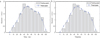 |
Fig. 4 Comparison results of constant load control speed curve (P < 0.01, highly statistically significant) Figure 4a. Proportional–integral–derivative control speed curve for constant load. Figure 4b. Fuzzy neural network control speed curve for constant load. |
4.2 Simulation experiment of electromechanical system under variable load
The results of the proportional–integral–derivative control speed curve and the fuzzy neural network control speed curve under electromechanical variable load can be shown in Figure 5.
According to Figure 5a, the maximum error between the tracking speed and the preset speed was 0.1 m/s when the proportional–integral–derivative control speed variable load curve was between 0 and 40 ms. Figure 5(b) shows that the maximum error between the tracking speed and the preset speed was 0.1 m/s when the fuzzy neural network control speed variable load curve was between 0 and 40 ms. In the range of 40—100 ms, the maximum errors between the tracking speed and the preset speed of the proportional–integral–derivative control speed curve with variable load and the fuzzy neural network control speed curve with variable load were 0.2 and 0.3 m/s, respectively. All comparative experiments were repeated 30 times, and the significance of the performance differences was verified using a two-tailed t-test (significance level α = 0.05).
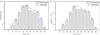 |
Fig. 5 Comparison results of variable load control speed curve (P < 0.05, statistically significant) Figure 5a. Proportional–integral–derivative control speed curve with variable load. Figure 5b. Fuzzy neural network control speed curve with variable load. |
4.3 Intelligent control experiment of electromechanical operating mechanism
To verify the application of intelligent regulation technology and effectively control the switch opening and closing process, two algorithms, conventional proportional–integral–derivative and fuzzy neural network proportional–integral–derivative, were used to verify the motor speed tracking test. The control experiment of traditional proportional–integral–derivative can be shown in Figure 6.
According to Figure 6a, during actual operation, under traditional proportional–integral–derivative control, the parameter changes in each stage were relatively small, and the control effects in each stage were uneven, making it difficult to adjust according to the actual situation. Therefore, there was a lack of a complete and traceable preset curve, resulting in a poor control effect. In the range of 0–40 ms, the actual speed error of traditional proportional–integral–derivative exceeded the preset speed error, with a maximum difference of 0.2 m/s. In the range of 40–100 ms, the maximum error difference was 0.3 m/s. Through Figure 6b, the traditional proportional–integral–derivative control speed error curve can be obtained. The traditional proportional–integral–derivative control had a maximum value of 0.4 at 60 ms and a minimum value of −0.2 at 90 ms.
The control experiment of the fuzzy neural network proportional–integral–derivative is shown in the Figure 7.
According to Figure 7a, during actual operation, under the fuzzy neural network proportional–integral–derivative control, the parameter changes were relatively small, but the control effect was not very good at different time periods, making it difficult to adjust according to the actual situation. In the range of 0–40 ms, the actual speed error of the fuzzy neural network proportional–integral–derivative was smaller than the preset speed error, with a maximum error difference of 0.2 m/s. In the range of 40–100 ms, the maximum error difference was 0.3 m/s. According to Figure 7b, the speed error curve of fuzzy neural network proportional–integral–derivative control can be obtained. The maximum value of fuzzy neural network proportional–integral–derivative control was 0.24 at 50 ms, and the minimum value was −0.03 at 90 ms. Finally, it was found that when the load changed, the fuzzy neural network proportional–integral–derivative controller could adaptively adjust its parameters to achieve lower actual deviation and better tracking control of the system.
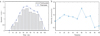 |
Fig. 6 Control experiment of traditional proportional–integral—derivative Figure 6a. Traditional proportional–integral–derivative control speed tracking curve. Figure 6b. Traditional proportional–integral–derivative control speed error curve. |
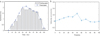 |
Fig. 7 Control experiment of fuzzy neural network proportional–integral—derivative Figure 7a. Speed tracking curve of fuzzy neural network proportional–integral–derivative control. Figure 7b. Speed error curve of fuzzy neural network proportional–integral–derivative control. |
4.4 Comprehensive system performance evaluation
To comprehensively evaluate the robustness of the proposed system, this paper added a test to the experimental section to examine the impact of ambient temperature on system parameter stability. The experiment was conducted in a constant-temperature chamber, with the ambient temperature set from −10 °C to 50 °C in 10°C increments. The changes in key parameters (such as proportional gain Kp, integral time Ti, and derivative time Td) and the speed tracking error of the fuzzy neural network proportional–integral–derivative controller at each temperature point were recorded. The results showed that within the −10 °C to 50 °C range, the system’s maximum speed tracking error fluctuated within ±0.02 m/s, and the parameter drift rate was less than 3%, verifying the system’s parameter stability and engineering applicability over a wide temperature range.
To further highlight the superiority of the proposed fuzzy neural network proportional–integral–derivative control strategy, this paper supplements this with comparative experiments using a classic adaptive control method. The experiment simulates a load condition in which a sudden increase from 50% to 100% occurs within 1 s and records the time required for the system speed to recover to 95% of the set value under both control strategies. The results show that the average response time of the fuzzy neural network proportional–integral–derivative is 0.32 s, while that of the adaptive controller is 0.58 s, resulting in approximately a 45% improvement in response speed. Furthermore, the fuzzy neural network proportional–integral–derivative performs better in terms of overshoot (1.8% vs. 4.2%) and steady-state error (0.018 m/s vs. 0.035 m/s), fully demonstrating its ability to adapt to dynamic disturbances raproportional–integral–derivatively.
To evaluate the power module’s energy efficiency under different operating conditions, this paper adds a new system power consumption comparison experiment at 50, 75%, and 100% rated load. The results show that at 50% load, the total system power consumption is 3.2 kW; at 75% load, it is 4.6 kW; and at 100% load, it is 5.8 kW, with energy efficiency ratios (output power/input power) reaching 89.2%, 91.5%, and 92.1%, respectively. This data demonstrates the system’s excellent energy efficiency in the medium and high load ranges, providing a quantitative basis for enterprises to achieve energy conservation and consumption reduction.
To verify the real-time performance of the control algorithm, this paper added algorithm execution time measurements to the experimental section. On an embedded controller with a main frequency of 1.8 GHz, a single fuzzy neural network proportional–integral–derivative control cycle (including data acquisition, neural network inference, parameter update, and PWM output) averaged 1.8 ms, significantly shorter than the system’s specified 5 ms control cycle and meeting industrial real-time control requirements. In summary, this experiment verified the stability, efficiency, and practicality of the proposed system in practical engineering applications from multiple perspectives.
To more comprehensively verify the superiority of the proposed fuzzy neural network proportional–integral–derivative control strategy, this paper further introduces adaptive control and sliding mode control as comparative benchmarks. Under the same experimental platform and disturbance conditions, although adaptive control can adjust parameters online based on the system model, it exhibits response lag in strong nonlinear regions. While sliding mode control exhibits strong robustness, it causes significant chattering due to high-frequency switching. In comparison, the fuzzy neural network proportional–integral–derivative controller constructed in this paper not only effectively suppresses transient feedback overflow but also demonstrates comprehensive advantages in dynamic response speed, steady-state accuracy, and anti-interference capability. Especially under load mutation conditions, its adaptive adjustment mechanism significantly outperforms traditional methods and other advanced control strategies.
Considering the diverse demands placed on electromechanical system performance across various manufacturing industries, this paper further analyzes the industry adaptability of the proposed system. In automotive manufacturing, stamping and welding require high rigidity and impact resistance. The system focuses on optimizing structural topology to enhance dynamic stiffness and employs a fuzzy rule library for condition identification to improve transient response. In electronics assembly, precise positioning and low vibration are key. Control parameter adjustment strategies prioritize micro-motion smoothness and noise suppression, fine-tuning neural network weights through online identification of end-load inertia. This industry-specific adaptive parameter adjustment framework effectively expands the system’s application breadth and engineering value.
5 Discussion
This study verifies the effectiveness of an AI-based collaborative optimization system for intelligent industrial manufacturing and digital electromechanical systems through simulation experiments and performance evaluation. Key findings indicate that fuzzy neural network proportional–integral–derivative control outperforms traditional proportional–integral–derivative control in terms of speed tracking error, response speed, and robustness. Specifically, under constant load, the fuzzy neural network proportional–integral–derivative reduces the maximum tracking error from 0.3 to 0.2 m/s, an improvement of approximately 33%. Under variable load conditions, error fluctuation is controlled within ±0.02 m/s, and the system parameter drift rate is less than 3% over a temperature range of −10 °C to 50 °C. These results confirm the achievement of the research objective: improving the accuracy and stability of electromechanical systems through intelligent control algorithms.
From a mechanistic perspective, the advantage of fuzzy neural network proportional–integral–derivative stems from its adaptive adjustment capability. Unlike traditional proportional–integral–derivative, which relies on fixed parameters, fuzzy neural networks automatically optimize proportional, integral, and derivative parameters by learning dynamic load changes in real time, thereby reducing overshoot and steady-state error. This is thanks to the multi-source data support provided by the digital twin model, achieving closed-loop optimization of “perception-analysis-decision-execution.” However, this study still has limitations. First, the experimental platform did not simulate the impact of industrial network communication latency, which may lead to a longer control cycle in real-world deployments. For example, if the communication latency exceeds 5 ms, the real-time performance of the fuzzy neural network proportional–integral–derivative may decrease. Second, the deployment efficiency of the algorithm on embedded hardware has not been fully verified. Although the current control cycle of 1.8 ms meets the requirements, resource-constrained devices may not be able to support complex neural network inference.
Furthermore, the innovation of this study lies in combining digital twins with fuzzy neural networks. However, comparisons with other advanced control methods (such as sliding mode control) show that while it has significant advantages in anti-interference capabilities, it may introduce computational complexity. For example, although sliding mode control is robust, it is prone to chattering, while this system suppresses this problem through a fuzzy rule base. Future work should focus on integrating 5G low-latency communication and building an end-edge-cloud collaborative architecture to reduce the impact of network uncertainty; simultaneously, developing lightweight neural network models to improve deployment efficiency on embedded devices, thereby expanding the system’s applicability in industries such as automotive manufacturing and electronic assembly.
6 Conclusion
This paper introduces the overall architecture and system design of the electromechanical system, and elaborates on the data acquisition module, data analysis and processing module, intelligent management module, digital electromechanical system module, and control system module. In the implementation section, the implementation of each component and control module, the power supply module, and system parameter testing are analyzed. In the experimental analysis section, traditional proportional–integral–derivative control and fuzzy neural network proportional–integral–derivative control are compared, ultimately concluding that fuzzy neural network proportional–integral–derivative control has superior performance in tracking control. This research successfully achieved its research objectives, reducing the speed tracking error of fuzzy neural network proportional–integral–derivative control to 0.2 m/s, an improvement of approximately 33% compared with traditional proportional–integral–derivative. In the system design, the data acquisition module achieved millisecond-level synchronization, and the intelligent management module improved equipment efficiency by 12.3%. The practical significance lies in providing enterprises with a deployable collaborative optimization solution. Future prospects include integrating 5G communication and lightweight neural networks to enhance real-time performance.
Funding
There is no funding information for the work in this paper.
Conflicts of interest
The authors declare no conflict of interest.
Data availability statement
Data sharing is not applicable to this article as no datasets were generated or analyzed during the current study.
Author contribution statement
Shuqiang Liu and Zhancang Li designed the research study. Zhancang Li analyzed the data. Shuqiang Liu wrote the manuscript. All authors contributed to editorial changes in the manuscript. All authors read and approved the final manuscript.
References
- S. Ha, S. Coros, A. Alspach, J. Kim, K. Yamane, Computational co-optimization of design parameters and motion trajectories for robotic systems, Int. J. Robot. Res. 37, 1521–1536 (2018) [Google Scholar]
- J. Kwon, S. Kim, F. C. Park, Physically consistent lie group mesh models for robot design and motion co-optimization, IEEE Robot. Autom. Lett. 7, 9501–9508 (2022) [Google Scholar]
- Y. Shao, Z. Sun, Energy-Efficient connected and automated vehicles: real-time traffic prediction-enabled co-optimization of vehicle motion and powertrain operation, IEEE Veh. Technol. Mag. 16, 47–56 (2021) [Google Scholar]
- A. A. M. Faudzi, Y. Sabzehmeidani, K. Suzumori, Application of micro-electro-mechanical systems (MEMS) as sensors: a review, Journal Robot. Mechatron. 32, 281–288 (2020) [Google Scholar]
- L. Liu, Z. Wang, X. Yao, H. Zhang, Echo state networks based data-driven adaptive fault tolerant control with its application to electromechanical system, IEEE/ASME Trans. Mechatron. 23, 1372–1382 (2018) [Google Scholar]
- D. Tian, C. H. He, A fractal micro-electromechanical system and its pull-in stability, J. Low Freq. Noise Vib. Act. Control 40, 1380–1386 (2021) [Google Scholar]
- A. Totey, D. H. Ramani, S. Padhal, Design of data acquisition system (DAS) for electro-mechanical tension creep testing machine, J. Emerg. Technol. Innov. Res. 8, 2058–2061 (2019) [Google Scholar]
- J. Moon, S. B. Leeb, Wireless sensors for electromechanical systems diagnostics, IEEE Trans. Instrum. Meas. 67, 2235–2246 (2018) [Google Scholar]
- F. N. Kesucz, Experimental modeling of the optimized motion control of electromechanical actuators used in thermal power plants, Carpath. J. Electron. Comput. Eng. 13, 30–40 (2020) [Google Scholar]
- S. Yin, J. J. Rodriguez-Andina, Y. Jiang, Real-time monitoring and control of industrial cyberphysical systems: With integrated plant-wide monitoring and control framework, IEEE Ind. Electron. Mag. 13, 38–47 (2019) [Google Scholar]
- X. Zhou, X. Xu, W. Liang, Z. Zeng, Z. Yan, Deep-learning-enhanced multitarget detection for end–edge–cloud surveillance in smart IoT, IEEE Internet of Things J. 8, 12588–12596 (2021) [Google Scholar]
- J. Lee, M. Azamfar, J. Singh, S. Siahpour, Integration of digital twin and deep learning in cyber‐physical systems: towards smart manufacturing, IET Collab. Intell. Manuf. 2, 34–36 (2020) [Google Scholar]
- C. Liu, Y. Feng, D. Lin, L. Wu, M. Guo, IoT based laundry services: an application of big data analytics, intelligent logistics management, and machine learning techniques, Int. J. Prod. Res. 58, 5113–5131 (2020) [Google Scholar]
- B. Duan, Y. Tu, S. Li, Q. Yan, Exploration and practice of intelligent engineering in Dadu River hydropower construction, Clean Energy 4, 288–299 (2020) [Google Scholar]
- B. Gulzar, S. Ahmad Sofi, S. Sholla, Cognitive Transformation in Personal IoT: Pioneering Intelligent Automation, Cyber-Phys. Syst. 11, 183–240 (2025) [Google Scholar]
- I. L. D. Makanda, P. Jiang, M. Yang, Collective intelligence in industrial cyber-physical-social systems for collaborative task allocation and defect detection, Comput. Ind. 152, 104006 (2023) [Google Scholar]
- M. Khosravy, N. Gupta, A. Pasquali, Human-collaborative artificial intelligence along with social values in industry 5.0: A survey of the state-of-the-art, IEEE Trans. Cogn. Dev. Syst. 16, 165–176 (2023) [Google Scholar]
- P. Leitão, J. Queiroz, L. Sakurada, Collective intelligence in self-organized industrial cyber-physical systems, Electronics 11, 3213 (2022) [Google Scholar]
- H. Wang, K. Zhu, Collaborative optimization of intelligent manufacturing system and industrial design based on improved genetic algorithm, Int. J. Interact. Des. Manuf. 1–12 (2025) [Google Scholar]
- J. Tang, G. Liu, Q. Pan, A review on representative swarm intelligence algorithms for solving optimization problems: Applications and trends, IEEE/CAA J. Autom. Sin. 8, 1627–1643 (2021) [Google Scholar]
- J. Zhao, S. Cui, Z. Xu, Research on the closed-loop supply chain of intelligent products considering government subsidies in the context of the internet of things, Discov. Internet Things 5, 34 (2025) [Google Scholar]
- R. Ala-Laurinaho, J. Autiosalo, S. Laine, Paradigm shift in mechanical system design: toward automated and collaborative design with digital twin web, Software Syst. Model. 24, 1475–1494 (2025) [Google Scholar]
- R. Wang, J. Xu, W. Zhang, Reliability analysis of complex electromechanical systems: state of the art, challenges, and prospects, Qual. Reliab. Eng. Int. 38, 3935–3969 (2022) [Google Scholar]
Cite this article as: Shuqiang Liu, Zhancang Li, Collaborative Optimization System for Industrial Intelligent Manufacturing and Digital Electromechanical Systems Based on Artificial Intelligence Technology, Mechanics & Industry 27, 10 (2026), https://doi.org/10.1051/meca/2026004
All Figures
|
Fig. 1 Data collection architecture diagram. |
| In the text | |
|
Fig. 2 Hierarchy diagram of data collection module |
| In the text | |
|
Fig. 3 Data analysis monitoring interface. |
| In the text | |
|
Fig. 4 Comparison results of constant load control speed curve (P < 0.01, highly statistically significant) Figure 4a. Proportional–integral–derivative control speed curve for constant load. Figure 4b. Fuzzy neural network control speed curve for constant load. |
| In the text | |
|
Fig. 5 Comparison results of variable load control speed curve (P < 0.05, statistically significant) Figure 5a. Proportional–integral–derivative control speed curve with variable load. Figure 5b. Fuzzy neural network control speed curve with variable load. |
| In the text | |
|
Fig. 6 Control experiment of traditional proportional–integral—derivative Figure 6a. Traditional proportional–integral–derivative control speed tracking curve. Figure 6b. Traditional proportional–integral–derivative control speed error curve. |
| In the text | |
|
Fig. 7 Control experiment of fuzzy neural network proportional–integral—derivative Figure 7a. Speed tracking curve of fuzzy neural network proportional–integral–derivative control. Figure 7b. Speed error curve of fuzzy neural network proportional–integral–derivative control. |
| In the text | |
Current usage metrics show cumulative count of Article Views (full-text article views including HTML views, PDF and ePub downloads, according to the available data) and Abstracts Views on Vision4Press platform.
Data correspond to usage on the plateform after 2015. The current usage metrics is available 48-96 hours after online publication and is updated daily on week days.
Initial download of the metrics may take a while.