| Issue |
Mechanics & Industry
Volume 18, Number 4, 2017
|
|
|---|---|---|
| Article Number | 405 | |
| Number of page(s) | 7 | |
| DOI | https://doi.org/10.1051/meca/2017028 | |
| Published online | 28 August 2017 | |
Regular Article
Determination of effective involute parameter limit in generation simulation of gears manufactured by rack-type cutters
Istanbul University, Department of Mechanical Engineering,
34320
Istanbul, Turkey
* e-mail: This email address is being protected from spambots. You need JavaScript enabled to view it.
Received:
4
October
2016
Accepted:
30
May
2017
Abstract
This paper studies the computerized tooth profile generation of involute gears cut with rack-type cutters. Based on the theory of gearing the mathematical models of generating cutter with asymmetric involute teeth and generated involute gears are given. Beveloid (conical involute) gears are considered for a generalized type of involute gearing for connecting parallel shafts. Effective limits of involute design parameters that determine the actual tip circle radii of the generated gears are investigated. An approach based on contact path of mating gears is proposed to eliminate further operations for standard value of tip circle radius. Computer simulation programs are developed to obtain graphs of generating tools and generated teeth surfaces.
Key words: Beveloid gears / asymmetric involute profile / contact path / generation simulation / effective parameter limit
© AFM, EDP Sciences 2017
1 Introduction
Computer simulation of involute gear generating process has been studied by various authors. A reliable numerical analysis of gear tooth bending or contact stresses for simulating the behavior of gears under working conditions needs precisely determined tooth profile of the machined gear. Therefore, an accurate mathematical model of the gear tooth should be established.
In literature, mathematical modeling of involute gears generated by rack- or pinion-type cutters have been presented [1–4]. Litvin proposed the Vector Method to develop mathematical models for describing generating and generated teeth surfaces of the various types of gears [4]. This method can also consider functional or production-required tooth modifications. Based on Litvin's Vector Method, various authors studied the modeling, undercutting and stress analyzing of conventional and modified gears [5–24].
Vector representation of the generating cutters includes the topland, tip fillet and involute regions. According to the cutter geometry and an appropriate coordinate system, the position vector of generating surface can be expressed. The design parameter of the generating cutter surface which determines the location of points on the related region has upper and lower limits according to the geometry. Then matrix transformation, differential geometry and gear theory are applied to obtain gear tooth surface [4].
In the papers about mathematical modeling of the generating and generated teeth surfaces, the limits of involute region design parameters are given for exact geometry of the cutter but obtained gear teeth profile may extend above the standard tip circle. This fact can be observed in the papers about pinion-type generation [6,15,22,23] and rack-type generation [5,7,12–14] for example. There should be an effective upper limit of the involute parameter to calculate the exact tip radius of the generated gear. Path of contact for rack and gear may give information about the effective parameter in case of generating with a rack cutter. Thus, without a further CAD operation or an iterative method, the standard tip radius of the involute gear can be obtained.
This paper deals with the determination of the upper limit of the rack cutter's involute region that gives the standard tip circle of the generated gear. The relation between length of path of recess and effective limit is investigated. A general model of involute gears (helical beveloid) is considered for verification and validation of the proposed approach. Beveloid gears can be used in transmissions with intersecting or skewed axes or in transmissions with parallel axes for backlash-free operation. In precision mechanisms gears should be designed to have no backlash [25,26].
The rest of this paper is organized as follows. In the next sections, the mathematical model of the generating cutters is studied. The mathematical models: the locus of the generating-type cutter surfaces, the equation of meshing and the generated gear tooth surfaces, are given in Sections 2 and 3. Converting to the two-dimensional modeling is presented in Section 4. The effective upper limits of involute parameters for rack-type generation are presented in Section 5. Computers graphs of generating and generated surfaces are given in Section 6. Results are discussed in Section 7. Finally, a conclusive summary of this study is given in Section 8.
2 Mathematical model of generating cutter
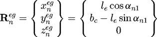
The normal section of a standard rack cutter with a complete generating surface is shown in Figure 1. Regions in the generating surface can be classified as the topland, tip fillet and involute regions. In the case of asymmetric tooth, these regions are designed according to corresponding sides pressure angles.
As shown in Figure 1, regions  and
and  of the rack cutter are straight lines that generate different working sides of the involute gears. mn is the normal module of the rack cutter with a asymmetric tooth profile. αn1 and αn2 are the normal pressure angles. The position vector of regions
  and
and  are represented in coordinate system Sn(Xn, Yn, Zn) as follows [13]:
 (1)
(1)
 (2)
where le and lf are curvilinear parameters of rack cutter surface which determine the location of points on working surface. le and lf are limited by −ha/cos αn1 ≤ le ≤ ht/cos αn1 and −ha/cos αn2 ≤ lf ≤ ht/cos αn2 for left- and right-side of the rack cutter respectively.
(2)
where le and lf are curvilinear parameters of rack cutter surface which determine the location of points on working surface. le and lf are limited by −ha/cos αn1 ≤ le ≤ ht/cos αn1 and −ha/cos αn2 ≤ lf ≤ ht/cos αn2 for left- and right-side of the rack cutter respectively.
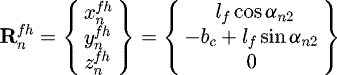
To obtain a generalized mathematical model of involute gears, additional coordinate systems should be used and appropriate coordinate transformations between these systems should be applied. In the first step, the rack cutter surface for the helical gear generation is simulated. The normal section of the rack cutter, attached to the coordinate system Sn, is translated along the line  as shown in Figure 2. Therefore,
  is also one of the design parameters of the rack cutter surface, and β is the helix angle (RH) of the generated helical gear. The plane YpZp can be regarded as the pitch plane of the rack cutter [7]. The coordinate transformation matrix from coordinate system Sn to Sp can be written as follows:
 (3)
(3)
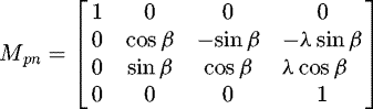
In the second step, the taper hobbing process is simulated. The generating cutter is inclined to the gear axis by the cone angle δ as shown in Figure 3. As a result, the rack cutter is represented in the plane axode coordinate system Sc(Xc, Yc, Zc) [7]. The coordinate transformation matrix from coordinate system Sp to Sc can be written as follows:
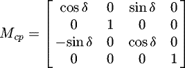 (4)
(4)
The position vector of generating cutter represented in coordinate system Sc(Xc, Yc, Zc)can be written as follows:
 (5)
where superscript i represents regions
(5)
where superscript i represents regions  ,
,  ,
,  ,
,  ,
,  and
and  . We can write down the equations of generating surface in open form as follows:
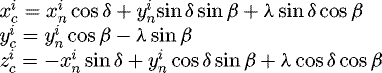 (6)
(6)
Tangent plane or tangent vectors determine the existence of regular surfaces. The tangent plane of the generating cutter surface is composed of two vectors: ∂Rc/∂lj and ∂Rc/∂λ (partial derivatives). Surface normal is given by the cross product of the partial derivatives. According to differential geometry and gear theory, normal vectors of regions  of the rack cutter surface can be represented in coordinate system Sc by the following equation [4].
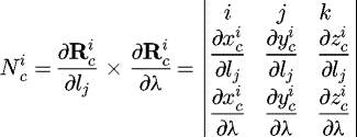 (7)
(7)
The unit normal vector of the rack cutter surface is represented by equation (8) [4].
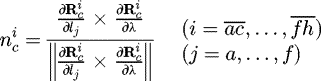 (8)
(8)
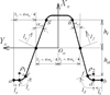 |
Fig. 1 The normal section of the rack cutter. |
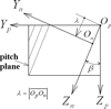 |
Fig. 2 Formation of rack cutter surface for helical gear generation. |
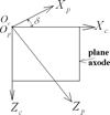 |
Fig. 3 Formation of rack cutter surface for beveloid gear generation. |
3 Mathematical model of generated gear
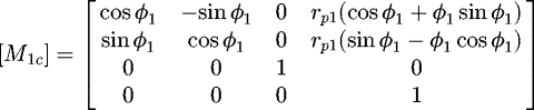
Figure 4 depicts the coordinate relationship between the rack cutter and the generated gear. Coordinate system Sh(Xh, Yh, Zh) represents the fixed coordinate system. Sc(Xc, Yc, Zc) is the plane axode coordinate system attached to the rack cutter and coordinate system S1 (X1, Y1, Z1) is attached to the generated gear [7]. While the gear blank rotates through an angle φ1, the rack cutter translates the linear displacement S = rp1φ1 along Yc axis. Therefore, the coordinate transformation matrix from Sc to S1 can be described as [4]:
 (9)
(9)
Fundamental law of gearing states that the common normal to the transverse section of the cutter and the gear tooth surface must pass through the instantaneous center of rotation (pitch point). Therefore, the equation meshing can be represented using coordinate system Sc(Xc, Yc, Zc) as follows [4]:
 (10)
where
(10)
where  ,
,  and
and  are the coordinates of a point on the instantaneous axis of gear rotation I–I represented in coordinate system Sc;
  ,
,  and
and  are the surface coordinates of the rack cutter; symbols
  ,
,  and
and  symbolize the components of the common unit normal represented in coordinate system Sc.
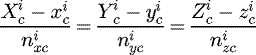
According to the theory of gearing [4], the mathematical model of the generated gear tooth surface is a combination of the meshing equation and the locus (family) of the rack cutter surfaces. The locus of the cutter surface, expressed in coordinate system S1, can be determined as follows [4]:
 (11)
(11)
As a result, the mathematical model of the gear tooth surfaces can be obtained by simultaneously considering equations (11) and (10).
Helical beveloid gear is the generalized model of the involute gears mounted on parallel axes. Straight conical involute gears, helical gears and spur gears can be represented by the equations by letting the helix angle, the cone angle, or both be equal to zero [10].
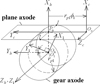 |
Fig. 4 Coordinate relationship between rack cutter and generated gear. |
4 Tooth profile analysis on the plane of rotation
In beveloid gears profile shift varies along the facewidth. As a result the tooth geometry changes across the facewidth. Moreover helix angle also alters the geometry. Contact path, zero topland and undercutting should be investigated in several transverse planes. To express the profile of the imaginary rack cutter on the plane of rotation YcZc, the third item of equation (6) can be adopted as follows:
 (12)
(12)
Considering the first two items of equation (6) together with equation (12), the profile of the two-dimensional rack cutter can be obtained and expressed on the plane of rotation by treating zc as a constant. An important macrogeometric property of helical beveloid gear is the different transverse pressure angles on left- and right sides that results asymmetric teeth profiles [7,10,25,27]. Transverse pressure angles are formulated in equations (13) and (14).
 (13)
(13)
 (14)
(14)
5 Contact path and determination of effective parameter limit
Figure 5 depicts the line of action in meshing of the rack cutter and the helical gear being generated at a transverse section. The upper end of path of contact is point T where the tip circle of the pinion intersects the line of action.  is the length of path of recess. From the gear geometry,
  can be calculated as
 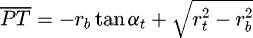 where rb is the base circle radius of the generated gear and αt is the transverse pressure angle. Therefore, the effective upper limit of the involute parameter is calculated as
 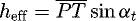 . As a result, when calculating the generated profile we should use −ha/cos αn1 ≤ le ≤ heff/cos αn1 instead of −ha/cos αn1 ≤ le ≤ ht/cos αn1.
The equation of effective limit can also be extended for beveloid gears. We can write  for a transverse section zc along the face width of a beveloid gear. The pressure angles on plane of rotation can be calculated as tan αt = tan αn cos δ for straight beveloid and tan αt = ∓ tan β sin δ + tan αn cos δ sec β for helical beveloid tooth where δ is the cone angle and β is the helix angle.
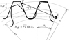 |
Fig. 5 Meshing diagram of a rack cutter and pinion. |
6 Computer applications
Based on the mathematical models given in previous sections, computer programs can be developed to obtain the coordinates of the generating cutters and generated gears. In this study the program is written with GW-BASIC. Output of files is evaluated with GRAPHER to obtain computer graphs.
Figure 6 displays a transverse section of a helical gear with symmetric involute teeth. In this example, design parameters are selected as: normal module mn = 5 mm, normal pressure angle αn1 = 20°, helix angle β = 15° and number of teeth T = 13. The proposed limit of the design parameter gives the exact length of involute profile that is limited by standard tip circle radius of the workpiece.
Figure 7 displays a transverse section of a straight beveloid gear. In this example, design parameters are selected as: normal module mn = 5 mm, normal pressure angle αn1 = 20°, cone angle δ = 15°, number of teeth T = 25 and with a cross-section constraint zc = − 10 mm. A negative profile shift coefficient appears near the heel so undercutting is observed. Transverse pressure angle is calculated as αt = 19.37°.
Figure 8 displays a transverse section of a helical beveloid gear. In this example, design parameters are selected as: normal module mn = 5 mm, normal pressure angle αn1 = 20°, helix angle β = 15°, cone angle δ = 15°, number of teeth T = 25 and with a cross-section constraint zc = 0. Asymmetric tooth profile on the plane of rotation is observed. Transverse pressure angles on the left- and right sides are αt1 = 16.41602° and αt2 = 23.42808°, respectively. Selected parameters in this example produces the left side profile be on the undercutting limit. As the conventional involute parameter limit is used on the left side, it gives extended involute profile above the standard tip circle.
Figure 9 displays a transverse section of a helical beveloid gear cut by a rack cutter with asymmetric teeth. Also relative positions of the generating cutter with respect to gear blank during generation process are illustrated. Design parameters are selected as: normal module mn = 5 mm, left side normal pressure angle αn1 = 26.68735°, right side normal pressure angle αn2 = 20°, helix angle β = 15°, cone angle δ = 15°, number of teeth T = 25 and with a cross-section constraint zc = 0. Transverse pressure angles are calculated as αt1 = 23.42808° and αt2 = 23.42808° for left- and right sides, respectively. Therefore a symmetric profile on the plane of rotation can be obtained.
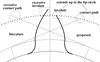 |
Fig. 6 Helical gear tooth profile. |
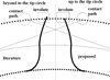 |
Fig. 7 Straight beveloid gear tooth profile. |
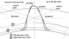 |
Fig. 8 Helical beveloid gear tooth profile. |
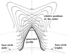 |
Fig. 9 Helical beveloid gear generated by an asymmetric cutter. |
7 Results
Generating-type cutters are widely used in mass production of gears. In literature most of studies about mathematical modeling and analysis of gears are based on Litvin's vector approach [4]. This approach begins with the parametric representation of tool surface in vector form. As the tool surface is composed of different regions, the intervals of curvilinear parameters that determine the position of a point in the region should maintain position, tangent, or curvature continuity of adjacent regions. This study presents an effective upper limit of involute parameter that gives the exact length of generated involute profile. As stated in Section 5, from the contact path of rack and gear mechanism radial distance from pitch point to the end point of contact can be defined as effective upper limit of involute parameter. This limit depends on the transverse section through the face width. Proposed formula is derived for generalized model of involute gears mounted on parallel axis.
In Section 6, illustrative examples are given. In Figures 6–8, the proposed upper limit of involute parameter is used for generated profile on the right side. On the left side, generated involute profile ends beyond the actual tip circle radius of the gear blank. The extended part should be trimmed.
Beveloid gears can be considered as involute gears with a linear variable profile shift along the face width. As the profile shift changes from a negative value to a positive value, undercutting and zero topland can be observed in several transverse sections of generated gear. Moreover, helix angle causes asymmetric profile on the plane of rotation. Figure 8 displays transverse section of a helical beveloid gear that has different pressure angle on left and right sides. As the transverse pressure angle decreases the risk of undercutting increases. To prevent undercutting in helical beveloid gears rack cutter with asymmetric involute teeth can be used. Figure 9 displays helical beveloid gear generated by a rack cutter with an asymmetric tooth flank.
The author used the locus equation of the cutter and obtained illustrations displaying relative positions of the cutter during generation by manipulating rolling parameter as −π/4 ≤ φ1 ≤ π/4 in the developed code. An example is illustrated in Figure 9. It has been reported in literature that the relative positions provide a basis to determine the chip geometry [28].
Like as in manufacturing cylindrical involute gears, hobbing tools are used for beveloid gearing. Conventional gear hobbing machines are arranged with the methods proposed by Mitome [27]. They are the inclined-work-arbor taper hobbing method and the table-sliding taper hobbing method. Also generating grinding wheels can be used. Hobbing or grinding is simulated by an imaginary rack cutter in computer applications.
The coordinates of the points on the gear tooth can also be imported into a CAD software to obtain 3-D models of gears for 3D Printing. Then it is exported to 3D Printing Machines where physical model of gears can be obtained. Figure 10 displays a solid model of a straight beveloid gear. In this study, prototypes of straight beveloid gears are also manufactured by a 3-D printer that runs on fused deposition modeling (FDM) technology. Figure 11 displays straight beveloid gears made from polylactide (PLA).
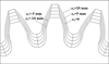 |
Fig. 10 Solid model of a straight beveloid gear. |
 |
Fig. 11 3-D printed straight beveloid gears. |
8 Conclusions
Generating-type of cutters is widely used in mass production of involute gears. In this study, mathematical models of rack cutters and beveloid gears are given, taking into account the asymmetric involute tooth profile. In the open literature obtained gear teeth involute profile may extend above the standard tip circle when using upper limit of involute parameter for the profile of cutter. Major finding in this paper is the concept of analytically derived effective upper limit of involute parameter. This approach eliminates CAD operations or iterative methods needed to correct the involute profile exceeding the limit that occurs when using design parameters in the conventional range. Examples for different cases are presented to validate the proposed approach.
Undercutting and zero topland should be checked in beveloid gears due to varying profile shift from toe to heel. For helical beveloid gears cutters with asymmetric involute teeth can be used to prevent the undercutting on the related side.
The relative positions of the generating cutter can also be illustrated. Chip geometry can be described from the relative positions. The description of chip geometry can be used predicting the tool life and cutting forces for manufacturing in further studies.
In addition to hobbing and grinding, the additive manufacturing methods (3D printing) can also be used for producing beveloid gears. The mathematical model given in this study can also be used to obtain 3-D models in a CAD software. 3D CAD models can be obtained from several transverse sections by using extrude/sweep operations.
Beveloid gears have found wide application in marine transmission and automotive industry. Beveloid gearing is a cheaper means of limiting backlash in precision mechanisms such as industrial robots. In further studies based on beveloid gears, mechanical aspects such as friction and wear can be considered. A wear-modified model proposed by Brauer and Andersson can be extended to helical beveloid gears [26]. Modifications such as tip chamfering, parabolic tooth and root free-cut can be applied to the mathematical model of generating cutter. These aspects are beyond to the scope of this study.
Nomenclature
bc: tool setting of the rack cutter
ha: tool setting of the rack cutter
ht: tool setting of the rack cutter
mn: normal module
mt: transverse module
lj: curvilinear coordinates of rack cutter where subscript j = a, b, c, d, e, f
[M1c]: coordinate transformation matrix from coordinate system Sc to S1
nc: unit normal vector of rack cutter surface
 :
position vector rack cutter surface for gear generation
:
position vector rack cutter surface for gear generation
 :
position vector of rack cutter normal section where superscript i represents regions
:
position vector of rack cutter normal section where superscript i represents regions  ,
,  ,
,  ,
,  ,
,  and
and  of the rack cutter surface
 :
the family of the rack cutter surfaces
:
the family of the rack cutter surfaces
rb: radius of base circle of generated gear
rp1: radius of pitch circle of generated gear
rt: radius of tip circle of generated gear
Sc: rack cutter coordinate system
Sf: fixed coordinate system
S1: gear blank coordinate system
T: number of teeth of generated gear
αn1: normal pressure angle of the rack cutter (left side)
αn2: normal pressure angle of the rack cutter (right side)
αt: transverse pressure angle
β: helix angle
δ: cone angle
φ1: motion parameter
ρ1: left tip fillet radius of the cutter
ρ2: right tip fillet radius of the cutter
References
- E. Buckingham, Analytical mechanics of gears, McGraw-Hill, New York, 1988 [Google Scholar]
- C. Salamoun, M. Suchy, Computation of helical or spur gear fillets, Mech. Mach. Theory 8 (1973) 305–323 [CrossRef] [Google Scholar]
- J.R. Colbourne, The geometry of involute gears, Springer-Verlag, New York, 1987 [Google Scholar]
- F.L. Litvin, Gear geometry and applied theory, Prentice-Hall, New Jersey, 1994 [Google Scholar]
- C.-B. Tsay, Helical gears with involute shaped teeth: geometry, computer simulation, tooth contact analysis and stress analysis, J. Mech. Des. 110 (1988) 482–491 [Google Scholar]
- S.-L. Chang, C.-B. Tsay, Computerized tooth profile generation and undercut analysis of noncircular gears manufactured with shaper cutters, J. Mech. Des. 120 (1998) 92–99 [CrossRef] [Google Scholar]
- C.-C. Liu, C.-B. Tsay, Tooth undercutting of beveloid gears, J. Mech. Des. 123 (2001) 569–576 [CrossRef] [Google Scholar]
- C.-C. Liu, C.-B. Tsay, Mathematical models and contact simulations of concave beveloid gears, J. Mech. Des. 124 (2002) 753–760 [CrossRef] [Google Scholar]
- G. Figliolini, J. Angeles, The synthesis of elliptical gears generated by shaper-cutters, J. Mech. Des. 125 (2003) 793–801 [CrossRef] [Google Scholar]
- J. Brauer, A general finite element model of involute gears, Finite Elem. Anal. Des. 40 (2004) 1857–1872 [CrossRef] [Google Scholar]
- K.J. Huang, H.W. Su, Approaches to parametric element constructions and dynamic analyses of spur/helical gears including modifications and undercutting, Finite Elem. Anal. Des. 46 (2010) 1106–1113 [CrossRef] [Google Scholar]
- C.-F. Chen, C.-B. Tsay, Tooth profile design for the manufacture of helical gear sets with small numbers of teeth, Int. J. Mach. Tool Manuf. 45 (2005) 1531–1541 [CrossRef] [Google Scholar]
- S.-C. Yang, Mathematical model of a helical gear with asymmetric involute teeth and its analysis, Int. J. Adv. Manuf. Technol. 26 (2005) 448–456 [CrossRef] [Google Scholar]
- S.-C. Yang, Study on an internal gear with asymmetric involute teeth, Mech. Mach. Theory 42 (2006) 977–994 [CrossRef] [Google Scholar]
- M.-F. Tsay, Z.-H. Fong, Novel profile modification methodology for moulded face-gear drives, J. Mech. Eng. Sci. 221 (2007) 715–725 [CrossRef] [Google Scholar]
- S.-Z. Wu, S.-J. Tsai, Contact stress analysis of skew conical involute gear drives in approximate line contact, Mech. Mach. Theory 44 (2009) 1658–1676 [CrossRef] [Google Scholar]
- C. Fetvaci, Computer simulation of helical gears with asymmetric involute teeth, J. Fac. Eng. Archit. Gazi Univ. 25 (2010) 441–447 [Google Scholar]
- C. Fetvaci, Generation simulation of involute spur gears machined by pinion-type shaper cutters, Stroj. Vestn. – J. Mech. Eng. 56 (2010) 644–652 [Google Scholar]
- W.-L. Chen, C.-B. Tsay, Mathematical model and tooth surfaces of recess action worm gears with double-depth teeth, Mech. Mach. Theory 46 (2011) 1840–1853 [CrossRef] [Google Scholar]
- Y.-C. Chen, C.-B. Tsay, Stress analysis of a helical gear set with localized bearing contact, Finite Elem. Anal. Des. 38 (2002) 707–723 [CrossRef] [Google Scholar]
- J.-H. Kuang, W.-L. Chen, Determination of tip parameters for the protuberance preshaving cutters, Mech. Mach. Theory 31 (1996) 839–849 [CrossRef] [Google Scholar]
- C.-B. Tsay, W.-Y. Liu, Y.-C. Chen, Spur gear generation by shaper cutters, J. Mater. Process. Technol. 104 (2000) 271–279 [Google Scholar]
- C. Fetvaci, Computer simulation of involute tooth generation, in: M. Gokcek (Ed.), Mechanical engineering, InTech, Rijeka, Croatia, 2012, pp. 503–526 [Google Scholar]
- C. Fetvaci, Computer simulation of helical gears generated by rack-type cutters, Arab. J. Sci. Eng. 36 (2011) 1321–1332 [CrossRef] [Google Scholar]
- J. Börner, K. Humm, F. Joachim, Development of conical involute gears (beveloids) for vehicle transmission, Gear Technol. 22(6) (2005) 28–35 [Google Scholar]
- J. Brauer, S. Andersson, Simulation of wear in gears with flank interference − a mixed FE and analytical approach, Wear 254 (2003) 1216–1232 [CrossRef] [Google Scholar]
- K. Mitome, Conical involute gear, part 1: design and production system, Bull. JSME 26(212) (1983) 299–305 [CrossRef] [Google Scholar]
- K.-D. Bouzakis, S. Kombogiannis, A. Antoniadis, N. Vidakis, Gear hobbing cutting process simulation and tool wear prediction models, J. Manuf. Sci. Eng. 124 (2002) 42–51 [CrossRef] [Google Scholar]
Cite this article as: M.C. Fetvaci, Determination of effective involute parameter limit in generation simulation of gears manufactured by rack-type cutters, Mechanics & Industry 18, 405 (2017)
All Figures
|
Fig. 1 The normal section of the rack cutter. |
| In the text | |
|
Fig. 2 Formation of rack cutter surface for helical gear generation. |
| In the text | |
|
Fig. 3 Formation of rack cutter surface for beveloid gear generation. |
| In the text | |
|
Fig. 4 Coordinate relationship between rack cutter and generated gear. |
| In the text | |
|
Fig. 5 Meshing diagram of a rack cutter and pinion. |
| In the text | |
|
Fig. 6 Helical gear tooth profile. |
| In the text | |
|
Fig. 7 Straight beveloid gear tooth profile. |
| In the text | |
|
Fig. 8 Helical beveloid gear tooth profile. |
| In the text | |
|
Fig. 9 Helical beveloid gear generated by an asymmetric cutter. |
| In the text | |
|
Fig. 10 Solid model of a straight beveloid gear. |
| In the text | |
|
Fig. 11 3-D printed straight beveloid gears. |
| In the text | |
Current usage metrics show cumulative count of Article Views (full-text article views including HTML views, PDF and ePub downloads, according to the available data) and Abstracts Views on Vision4Press platform.
Data correspond to usage on the plateform after 2015. The current usage metrics is available 48-96 hours after online publication and is updated daily on week days.
Initial download of the metrics may take a while.