| Issue |
Mechanics & Industry
Volume 21, Number 2, 2020
|
|
|---|---|---|
| Article Number | 211 | |
| Number of page(s) | 21 | |
| DOI | https://doi.org/10.1051/meca/2020008 | |
| Published online | 03 March 2020 | |
Regular Article
Dynamic characteristics for coal shearer cutting unit gearbox housing
1
School of Mechanical Engineering and Automation, Northeastern University, Shenyang 110819, PR China
2
Equipment Reliability Institute, Shenyang University of Chemical Technology, Shenyang 110142, PR China
* This email address is being protected from spambots. You need JavaScript enabled to view it.
Received:
19
October
2019
Accepted:
18
January
2020
Abstract
Long wall mining is most widely used in coal mining of China, and coal shearer is the most important machine due to its direct role in cutting coal. Nevertheless, coal mining enterprises are suffering from faults of coal shearer, especially cutting unit gearbox housing (CUGH). Published dynamic studies on CUGH have not considered the excitation caused by gear meshing and complete machine vibration. Due to the apparent lack of experimental validation of these published papers, the dynamic response of CUGH is not convincing. In this study, dynamic behavior of CUGH is investigated both theoretically and experimentally for finding out failure mechanism and improving reliability. Complete machine vibration and gear meshing vibration are two excitation sources for CUGH, and vibration is transferred via articulated holes and bearing holes. Hence, complete machine dynamics model is established for obtaining force on articulated holes. Dynamics model of gear transmission system is established for obtaining force on bearing holes. Stochastic cutting forces model is established as external load of complete machine dynamics model. Dynamics response is calculated by finite element model established by ANSYS. A measurement system to capture three-dimensional vibratory motions under realistic working conditions of coal mines is implemented by National Energy Mining Equipment Laboratory of China. Direct comparisons between predicted and measured results are presented to demonstrate the accuracy of the proposed model in predicting three-dimensional vibrations of CUGH. Maximum deformation and stress positions of CUGH are determined, and the excitation sources are investigated.
Key words: Coal shearer / Experimental study / Cutting unit gearbox housing / Dynamic characteristics / Long wall mining
© AFM, EDP Sciences 2020
1 Introduction
Coal, which makes up the proportion of 62% in whole energy consumption in 2017, is the most widely used energy and will be dominant resource of China for a long term since China is a coal-rich country. The “Action plan for energy technology revolution and innovation: 2016–2030” proposed jointly by National Development and Reform Commission and Nation Energy Administration of China pointed out that intelligent mining will be achieved by 2030 when unmanned working face will be basically achieved in some key mining areas [1]. Long wall mining, as shown in Figure 1, is the main coal mining method in China. Mining work face is a long wall and coal shearer cuts coal with the help of scraper conveyor. Then coal is transported out of working face by scraper conveyor and reversed loader. Safety of working space is guaranteed by hydraulic supports [2,3]. Among these coal mining equipment, coal shearer is the most important due to its direct role in coal cutting. CUGH (Fig. 2), whose role is supporting cutting drum and gear transmission system, enables cutting drum to cut coal in anywhere of coal wall. However, CUGH suffers from poor reliability in terms of the 11-year-period failure data collected by Wang and Zhou [4,5]. Recently, the largest coal mining enterprise in China-Shenhua Group, was taking effort to improve coal production through the methodology of raising mining height of working face to 8.8 m. However, Shenhua's effort was frustrated by the fracture of CUGH in cutting test since high mining working face leads to long force arm of CUGH and increases the risk of fracture. Hence, poor reliability of CUGH has been a key obstacle in the path of improving the productivity of long wall mining and causes great economical losses. For improving the reliability of CUGH in design stage, accurate dynamic model should be proposed and validated.
Finite element method is appropriate for establishing dynamic model since CUGH is a continuum with irregular shape. In fact, most scholars used finite element model in their papers for investigating dynamic characteristics of CUGH. Zhao et al. [6–15] used finite element models which are established by finite element or multi-dynamic software to study dynamic characteristics and reliability of CUGH. Their papers firstly use dynamics theories for studying CUGH, and without any doubt change the previous way of empirical design for determining design parameters. However, there are some disadvantages in their studies: (1) external excitations in their papers are inaccurate and some are neglected. According to the structure of cutting unit gearbox (Fig. 2), there are two external excitation sources: One is complete machine vibration and is transferred to CUGH via articulated holes. Complete machine dynamic model for coal shearer should be established for obtaining dynamic forces on articulated holes (connections of cutting unit and traction unit − Fig. 3). The other external excitation is gear meshing vibration of transmission system in cutting unit gearbox and the vibration is transferred to CUGH via bearing holes. Dynamic model for gear transmission system should be established for obtaining forces on bearing holes. Hence, the ignorance of these excitations will lead to inaccurate results. (2) Coal cutting forces on drum are taken as external excitations and applied directly on CUGH. However, this load applying method is inaccurate since cutting forces are transferred to gear transmission system via cutting drum and then to CUGH via bearing holes. (3) Dynamics results calculated by these papers are not validated by experiments. Recently, Liu et al. [15–20] conducted a series of experiments focusing on dynamics characteristics of cutting unit gearbox in coal cutting process. However, these papers mostly focused on dynamics of gear transmission system, and theoretical model for CUGH is not established. Liu et al. [21–23] focused on dynamics model of gear transmission system coupled with gearbox housing. However, these papers mainly investigated the influence of gearbox housing flexibility on the dynamic characteristics of gear transmission system. Recently, He and Peng [24] used wavelet decomposition method for noise reduction of experimental data and analyzed dynamic characteristics of CUGH.
To the best knowledge of these previous papers, this paper will try to provide a more accurate dynamic model of CUGH. Firstly, complete machine dynamics model of coal shearer is established for obtaining forces on articulated holes. Dynamic model for gear transmission system is established for obtaining dynamic forces on bearing holes. These forces are applied on finite element model of CUGH established by ANSYS software, and dynamics response is calculated. The accuracy of predictions from proposed dynamic model through direct comparisons to the experimental acceleration data.
 |
Fig. 1 Long wallmining(National Energy Mining Equipment Laboratory of China). |
 |
Fig. 2 Cutting unit gearbox housing (CUGH). |
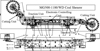 |
Fig. 3 MG500-1180/WD coal shearer. |
2 Complete machine dynamics model
2.1 Introduction of MG500-1180/WD coal shearer
MG500-1180/WD coal shearer (Fig. 2), which is made by China National Coal Group Co., Ltd, consists of 4 main parts: cutting unit, traction unit, electronic controlling unit and hydraulic unit. Main parameters of this coal shearer are shown in Table 1. In mechanical system, there are also 4 main parts: cutting unit, traction unit, cutting drum and housing structure. Different parts of mechanical system are connected by hinge joints and hydraulic bolts.
Main parameters of MG500-1180/WD.
2.2 Dynamics model
Before establishing dynamics model, the logical relationship between Sections 2 and 4 should be explained. This paper aims at investigating dynamic characteristics of CUGH. There are articulated holes and bearing holes on CUGH. The function of articulated holes is connecting CUGH with other parts of coal shearer and the function of bearing holes is supporting gear transmission system in gearbox. Hence, there are two external load sources for CUGH: one is complete machine vibration which is transferred to CUGH via articulated holes, the other is gear meshing vibration which is transferred to CUGH via bearing holes. Therefore, complete machine dynamics model is used for obtaining force on articulated holes and gear transmission dynamics model is used for obtaining force on bearing holes. Finally, external excitations on CUGH are obtained and Section 4 can be obtained and studied.
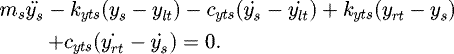
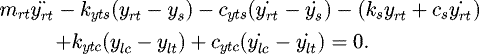
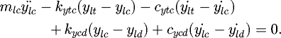
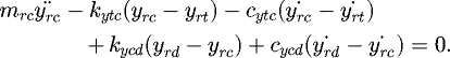
Cutting unit, traction unit, housing structure and cutting drum are simplified as 7 lumped mass in complete machine dynamic model, as shown in Figure 4. Connections of these components (hinge joints, hydraulic bolts and connection shafts) are represented by linear springs and damping. Transverse vibration degree of freedoms (DOFs) in XOY plane (shown in Fig. 4) is studied in this model and there are 14 DOFs in total. Driving forces of coal shearer in X direction are provided by gear meshing and supporting forces in Y direction are provided by sliding shoes.
Dynamics formulations are as follows (each term definition of Eqs. (1)–(14) is shown in Fig. 4).
The equations for left traction unit are: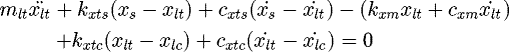 (1)
(1)
 (2)
(2)
The equations for housing structure are: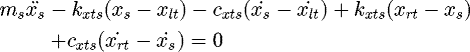 (3)
(3)
 (4)
(4)
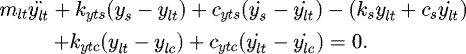
The equations for right traction unit are: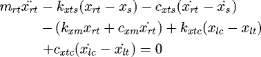 (5)
(5)
 (6)
(6)
The equations for left cutting unit are: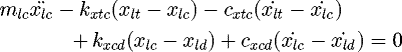 (7)
(7)
 (8)
(8)
The equations for right cutting unit are: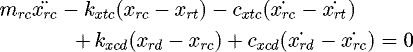 (9)
(9)
 (10)
(10)
The equations for left cutting drum are: (11)
(11)
 (12)
(12)
The equations for right cutting drum are: (13)
(13)
 (14)
(14)
According to instruction of MG500-1180/WD, constants in dynamics model such as mass, stiffness can be determined as.
The damping can be approximated as Rayleigh damping and damping matrix C is:
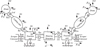 |
Fig. 4 Complete machine dynamics model of coal shearer. |
2.3 Stochastic cutting forces
Coal is cut by cutting picks fixed on drum and cutting force on drum is the superposition of forces on picks. Figure 5 shows the forces on one cutting pick, vq is traction speed of shearer, ω is rotation speed of drum, hmax is the maximum chip thickness, ∅i is position angle of pick. The average cutting resistance on single sharp pick Z0 is: (15)
(15)
 (16)
(16)
 (17)
(17)
 (18)
(18)
 (19)
(19)
 (20)where hz, f, A, Di,Sp, ϕb
bp, α, β, h are average chip thickness, consistence coefficient of coal seam, cutting resistance, diameter of pick tip, pick number of each cutting line, enclosed angle, calculation width of picks, cone angle, setting angle and cutting depth of picks.
(20)where hz, f, A, Di,Sp, ϕb
bp, α, β, h are average chip thickness, consistence coefficient of coal seam, cutting resistance, diameter of pick tip, pick number of each cutting line, enclosed angle, calculation width of picks, cone angle, setting angle and cutting depth of picks.
Average advancing resistance on single sharp pick: (21)
(21)
Average cutting, advancing resistance on single blunt pick: (22)
(22)
 (23)where f1, ky, Sd, σy are cutting resistance coefficient, ratio of average coal contact stress to unidirectional instantaneous compressive strength, blunt area of pick, uniaxial instantaneous compressive strength of coal.
Average lateral resistance of single blunt pick exists proportional relationships with cutting resistance Zav: (24)
(24)
Here, c1, c2, c3 are form coefficients; t is average intercept of cutting drum.
Randomness of cutting, advancing resistance is usually expressed by Gamma distribution, while lateral resistance is described by normal distribution. Li [24] proposed a Rayleigh-distribution-based method for solving the problem of Gamma process simulation. Therefore, stochastic cutting resistance is the sum of mean value and random component: (25)where n is sim points number, n = 1,2,3…; σz is mean square deviation of cutting resistance under Rayleigh distribution; kz [n] is stochastic coefficients of cutting resistance,
  –1.25,
  ,
,  , η1 [n], η2 [n] are independent normal random number order with 0 mean value and 1 standard deviation, ρ1 [n] is uniform distribution random number order in (0,1) interval.
Stochastic advancing resistance of single blunt pick is: (26)where σy is mean square deviation of cutting resistance under Gamma distribution, σy = 0.23Yav − 400; ky [n]is stochastic coefficients of advancing resistance,
  , η3 [n] are normal random number order with 0 mean value and 1 standard deviation.
Stochastic lateral resistance of single blunt pick is: (27)where σx is mean square deviation of lateral resistance under normal distribution, σx = 0.5Xav; kx [n]stochastic coefficients of lateral resistance,
  ; η4 [n] is normal random number order with 0 mean value and 1 standard deviation, ρ2 [n] is uniform distribution random number order in (0,1) interval.
Forward resistance Py, cutting resistance Pz, torque Mc on drum are superposition of forces on cutting picks: (28)
(28)
 (29)
(29)
 (30)where N is number of picks in cutting.
Axial force on drum A1: (31)where, Dc, Lc, Ld, J and K2 are drum diameter, distance between two guide sliding shoes, distance between guide sliding shoes and drum, width of drum and working condition coefficient (the value is usually 2).
In long wall mining, coal shearer will go oblique cutting (Fig. 12) with the help of scraper conveyor for cutting coal wall. Cutting depth increases in oblique cutting process and the number of picks N involved in cutting increases at the same time. Increase of N leads to the increase of Pz, Py, Mc and A1. Hence, the relationship between N and cutting depth d(t) is essential. For intuitively expressing, the picks arrangement on drum of MG500-1180/WD (Fig. 6) which is the coal shearer in experimental analysis of this paper is used. Maximum cutting depth dmax is 800 mm, and density of picks on drum is different along with cutting depth d(t). When 0 ≪ d (t) < 33 mm, N equals 4. When 0 < d (t) ≪ 100 mm, N increases by 3 with cutting depth d(t) increases 33mm. When 100 < d (t) ≪ 800 mm, N increases by 3 with cutting depth d(t) increases 100 mm. The relationship between N and cutting depth d(t) is shown in Table 3 .
Cutting depth d(t) can be described as follows: (32)where vq is traction speed of long wall shearer; θ is oblique angle (Fig. 12).
Substitute time-variant N into equations (28)–(30), and cutting force on drum in oblique cutting can be obtained.
Working conditions are based on realistic cutting process in coal mines: in oblique cutting, cutting depth increases from 0 to 600mm with constant traction speed 1.5 m/min; in straight line cutting, cutting depth and traction speed are 600 mm and 1.5 m/min, respectively.
Figure 7 shows the cutting forces on drum. Randomness can be obvious observed near and the mean values of cutting forces change regularly. Cutting resistance, forward resistance and torque in oblique cutting increase with cutting depth, and cutting forces in straight line cutting are larger than that in oblique cutting.
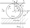 |
Fig. 5 Force diagram of the cutting drum. |
 |
Fig. 6 Picks arrangement on cutting drum of MG500-1180/WD. |
Some constants in complete machine dynamics model.
Relationship between N and cutting depth in MG500-1180/WD.
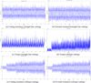 |
Fig. 7 Cutting forces on drum of MG500-1180/WD. (a) Cutting resistance (straight line cutting); (b) forward resistance(straight line cutting); (c) torque (straight line cutting); (d) torque (oblique cutting); (e) cutting resistance (oblique cutting); (f) forward resistance (oblique cutting). |
2.4 Dynamic forces on articulated holes
Dynamic forces on articulated holes are calculated by complete machine dynamics model, as shown in Figure 8. It can be seen that peak values of the second vibration period are close to the first period in straight line cutting but apparently larger in oblique cutting since cutting depth increases. Forces in Y direction are larger than X direction in both straight line and oblique cutting. This is mainly because the large deadweight for coal shearer. Maximum peak value is 61.4 KN and occurs in Y direction of straight line cutting. It is noted that forces in X direction fluctuate and curves in Y direction are smooth. This is because driving forces of coal shearer Fxm in X direction are provided by gear meshing and gear mesh stiffness fluctuates due to odd and even teeth alternating. Dynamic forces results are one of the external loads for CUGH and will be applied on finite element model of CUGH.
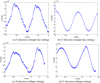 |
Fig. 8 Dynamic forces on articulated holes. (a) X direction (straight line cutting); (b) Y direction (straight line cutting); (c) X direction (oblique cutting); (d) Y direction (oblique cutting). |
3 Dynamics model of gear transmission system
Gear transmission system (Fig. 9) in CUGH, which consists of motor, two-stage spur gear transmission, two-stage plane gear transmission, one central large gear, is connected to cutting drum via a shaft. Some assumptions are put forward in terms of previous studies:
-
Basic characteristics for gear transmission system of cutting unit gearbox are low speed and high cutting forces. As Kahraman's research findings [26], nonlinearities caused by gear backlash and bearing clearances are neglected since very little nonlinear phenomena was found.
-
In terms of calculations of reference [27], stiffness of gear shafts are far greater than that of gear meshing, bearing support, elastic torsion shaft and connection shaft between different transmission stages. Hence, elastic deformation of gear shaft is neglected.
-
Transverse and rotational vibrations of gears are studied in this paper.
-
Bodies of shafts, gears, carriers, bearings are assumed to be rigid.
-
Planetary gears are assumed to be identical to each other in one transmission stage and uniform distributed around planetary carrier.
 |
Fig. 9 Gear transmission system. |
3.1 Dynamics model of gear transmission system
3.1.1 Forces and relative displacements
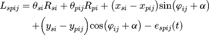
The relative displacements of gear mesh along the meshing line are: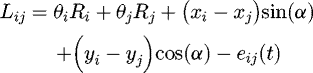 (33)
(33)
 (34)
(34)
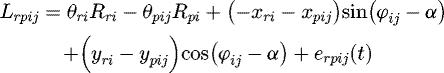 (35)where Lij is relative displacement of spur gear mesh, Lspij, Lrpij are relative displacements of planetary gear mesh, θ, ϕ and α are forced torsional vibration, position angle for planetary gear and press angle, respectively. R, x and y are base radius for gears, forced vibration response in x, y direction. Here, spr are sun gear, planetary gear and ring gear, ij in planetary gear meshes represent the transmission stage of planetary gear transmission and planetary gear number; ij in spur gear meshes represent gear number. sp, rp are sun-planetary gear mesh and ring-planetary gear mesh, respectively.
The mesh forces are: (36)
(36)
 (37)
(37)
 (38)The forces of support bearings are:
 (39)
(39)
 (40)Here, kxbj, cxbj, kybj, cybj are transverse stiffness and damping of the jth bearing.
The transverse forces between planetary carrier and planetary gears are: (41)
(41)
 (42)where, cp is planetary bearing between planetary gear and carrier.
The torsional torques and transverse forces between carrier of first stage and sun gear of second stage are: (43)
(43)
 (44)
(44)
 (45)where, c1s2 is carrier of first stage and sun gear of second stage.
The torsion torques and transverse forces between carrier of second stage and drum are: (46)
(46)
 (47)
(47)
 (48)where, c2d is carrier of second stage and drum, d is drum of SCUG.
The torsion torques and transverse forces between motor and spur gear transmission are: (49)
(49)
 (50)
(50)
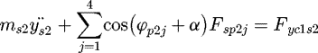
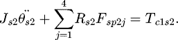
 (51)where, ms is motor and spur gear transmission.
The torsion torques and transverse forces between spur gears with same shaft are: (52)
(52)
 (53)
(53)
 (54)where, ij represents gear 3 and 4, gear 7 and sun gear s1.
3.1.2 Dynamics model formulation
The equations for motor are: (55)
(55)
 (56)
(56)
 (57)where m represents the motor and Tin is the input torque of the gear system.
The equations for gear 1 are: (58)
(58)
 (59)
(59)
 (60)The equations for gear 2 are:
 (61)
(61)
 (62)
(62)
 (63)The equations for gear 3 are:
 (64)
(64)
 (65)
(65)
 (66)The equations for gear 4 are:
 (67)
(67)
 (68)
(68)
 (69)The equations for gear 5 are:
 (70)
(70)
 (71)
(71)
 (72)The equations for gear 6 are:
 (73)
(73)
 (74)
(74)
 (75)The equations for gear 7 (central gear) are:
 (76)
(76)
 (77)
(77)
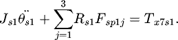
 (78)The equations of sun gear of first planetary transmission stage are:
 (79)
(79)
 (80)
(80)
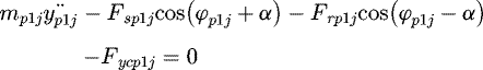
 (81)The equations of planetary gears of first planetary transmission stage are:
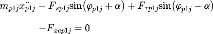 (82)
(82)
 (83)
(83)
 (84)The equations of ring gear of first planetary transmission stage are:
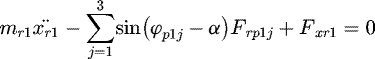 (85)
(85)
 (86)
(86)
 (87)where Tr1 is the braking torque of ring gear and Rr1 is the radius of ring gear.
The equations of carrier of first planetary transmission stage are: (88)
(88)
 (89)
(89)
 (90)Here, Fxb1c, Fyb1c are bearing support stiffness of carrier.
The equations of sun gear of second planetary transmission stage are: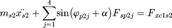 (91)
(91)
 (92)
(92)
 (93)The equations of motion for planetary gears of second planetary transmission stage are:
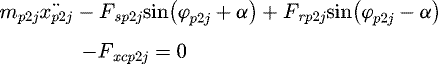 (94)
(94)
 (95)
(95)
 (96)The equations for ring gear of second planetary transmission stage are:
 (97)
(97)
 (98)
(98)
 (99)where Tr2 is the braking torque of ring gear and Rr2 is the radius of ring gear.
The equations for carrier of second planetary transmission stage are: (100)
(100)
 (101)
(101)
 (102)Here, Fxb2c, Fyb2c are bearing support stiffness of carrier.
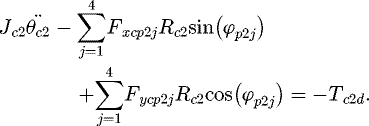
The equations of drum are: (103)
(103)
 (104)
(104)
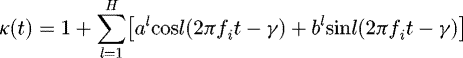
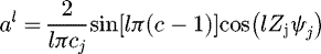
 (105)Mesh stiffness is described by the product of mean value and time-varying periodically component, and the time-varying component can be represented by Fourier series.
 (106)
(106)
 (107)
(107)
 (108)
(108)
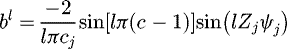 (109)where k (t) includes kij, kspij and krpij; kav is mean value corresponds to kij, kspij and krpij. i represents stage for both spur and planetary gear transmissions. j represents gear number in spur gear transmission, and planetary gear number in planetary gear transmission. fi is mesh frequency of the ith transmission stage. ψj is the position angle. cj is the theoretical involute contact ratio for gear meshes. γ is the relative phase between gear meshes and the arbitrarily chosen mesh (here, the chosen mesh is first sun-planetary mesh γsi1 = 0, i = 1,2).
Mesh stiffness and transmission error are two main high-frequency excitations for CUGH and the values of them depend on mesh phases. A variety of investigations has shown the powerful impact of mesh phasing on the dynamic characteristics of gear system. Therefore, obtaining the mesh phases of all gear meshes is essential. The value of relative mesh phase γ differs depending on arbitrarily chosen gear mesh (first sun-planetary mesh γs1 = 0) and meshing modes. Hence, γ includes 3 forms: γsn = γrn represents relative phase between nth sun/ring-planetary gear mesh and first sun/ring-planetary gear mesh; γio represents relative phase between different gear meshes on one gear. γio includes γioj (jth spur gear) and γioij (ith stage jth planetary gear); γj (j+1) represents relative phase between the reference teeth of gears mounted on the same shaft. Parker [28] investigated these mesh phasing relationships intensively, but the γP in his paper, which is the proportion of mesh period, can't be used in the expression of κ (t). Hence, the relationship between γP and γ is proposed in this paper as: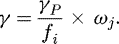 (110)Here, ωj is angular velocity of gear j (jth spur gear or ith stage jth planetary gear).
Proportional mesh damping in gear meshes are: (111)Here, m is sum mass of a pair of gears in mesh. A constant damping ratio ξ = 0.07 is employed as Kahraman used in reference [26].
Transmission error excitations caused by manufacturing deviations can also be represented by Fourier series and contain the same harmonic orders and phasing relationships as time-varying mesh stiffness. (112)
(112)
Here, eav
is mean transmission error of gear mesh; √kl2 +pl2
is the amplitude of the lth harmonic transmission error.Hence, the mass and stiffness matrices of gear transmission system can be given as: (113)Here, Mg, Mc, Md are mass matrices for gears, carriers and drum. M is a diagonal matrix; Kg, Ks, Kt are stiffness matrices for gear meshes, supporting and torsion connection shafts. Matrix assembly method for M and K can be found in literature [25], and damping matrices C share the same form as K.
The dynamic model of gear transmission system can be written in matrices form as:  (114)According to design parameters of coal shearer cutting unit gearbox, constants in dynamic model such as mass, moment of inertia, mean value of mesh stiffness, bearing stiffness, shaft stiffness, cutting forces on drum, can be determined and shown in Appendix A.
Figure 10 shows force on bearing holes of CUGH calculated by proposed dynamics model. It can be seen that times of load application vary with gear transmission stage, and times order from the most to the least is as follows: first spur gear transmission stage > second spur gear transmission stage>first planetary gear transmission stage > second planetary gear transmission stage. Time-variant mesh stiffness and transmission error are the source of excitation of the gear transmission system due to the shape of vibration response curve. The force of Y direction of second planetary gear transmission stage is largest and the peak value is 702.5 KN. It is worth noting that although force on bearing holes of planetary gear transmission are larger than spur gear transmission, the times of load application is less. Hence, the low reliability part in CUGH needs further investigation to determine.
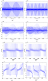 |
Fig. 10 Force on bearing holes of CUGH. (a) X direction of first spur gear transmission stage. (b) Y direction of first spur gear transmission stage. (c) X direction of second spur gear transmission stage. (d) Y direction of second spur gear transmission stage. (e) X direction of first planetary gear transmission stage. (f) Y direction of first planetary gear transmission stage. (g) X direction of second planetary gear transmission stage. (h) Y direction of second planetary gear transmission stage. |
4 Dynamics characteristics of CUGH
4.1 Finite element model
FE model for gearbox housing is established in terms of actual structure of MG500-1180/WD's CUGH, as shown in Figure 11. There are 178123 elements (Solid 185 in ANSYS) and 312564 nodes in FE model. Young's elastic modules, yield limit, Poisson's ratio and density of CUGH are 200 GPa, 300 Mpa, 0.3, and 7800 kg/m3. Condensed nodes, which are rigidly connected with bearing/articulated holes, are established by ANSYS in the center of bearing/articulated locations for applying external forces. Stochastic cutting forces, external forces on articulated holes and bearing holes are applied on FE model using transient dynamics analysis module in ANSYS. Simulation time is 2s in this paper due to limited computational capacity and high meshing frequencies in gear transmission system.
 |
Fig. 11 FE model for CUGH. |
4.2 Results and experimental validation
Stochastic cutting forces on drum are obtained by proposed model, as shown in Figure 7. Forces on articulated holes and bearing holes are obtained by complete machine dynamics model and gear transmission dynamic model, as shown in Figures 8–10. Apply these forces on articulated holes and bearing holes of CUGH finite element (FE) model, and then dynamic response of CUGH can be obtained.
Experiment, which can simulate realistic working conditions of coal shearer, is the best way for validating theoretical models. The coal cutting experiment of coal shearer is based on National Energy Mining Equipment Laboratory (Fig. 1) which has the same fully-mechanized mining equipment (coal shearer, scraper conveyor, etc.) with coal mines.
Test procedure was designed in terms of the realistic long-wall mining procedure, as shown in Figure 12. The left CUGH firstly went oblique cutting from right to left with constant traction speed 1.5 m/min and cutting depth range was 0–600 mm, while the right CUGH did not cut the coal wall. Traction speed increased after left CUGH went out of oblique cutting. Then the right CUGH went oblique cutting with traction speed range 1.5 m/min to 5 m/min and cutting depth range 0–600 mm. After the right CUGH went out of oblique cutting, traction speed decreased from 5 m/min to 0 m/min with constant cutting depth 600 mm. Sensors are arranged near bearing holes of spur gear and planetary gear transmission for obtaining three-directional acceleration, as shown in Figure 13. Sample frequency of sensors is 8500 Hz due to the high meshing frequencies for gear transmission system.
Figure 14 shows the measured acceleration results of coal cutting experiment. Here, the peak values of acceleration in these working conditions are selected for comparing the results of theoretical dynamics model and experiment: (1) straight line cutting, traction speed 5/min, cutting depth 600 mm (spur and planetary gear transmission); (2) oblique cutting, traction speed 1.5 m/min, cutting depth 100 mm, 300 mm (spur and planetary gear transmission). Table 4 shows the direct comparison between measured and predicted results for validating the accuracy of theoretical dynamics model. It can be seen that both the pick amplitudes of working conditions in straight line cutting as well as oblique cutting agree well. The largest relative deviation is 16.67% due to a certain amount of error for sensors measuring and theoretical modeling. Hence, the lumped mass dynamics model of cutting unit gearbox proposed here is quite accurate in predicting dynamics response of CUGH in spite of the fact that this model employs many assumptions.
To make the validation of proposed dynamic model more convincing, peak values of vertical acceleration in oblique cutting is directly compared. Traction speed in this comparison is 1.5 m/min, while cutting depth range is 0–600mm. Results of spur and planetary gear transmission are shown in Figure 15. Green lines represent measured results and blue lines represent predicted results. It can be seen that the trend of measured results agree well with predicted results.
 |
Fig. 12 Coal cutting process. |
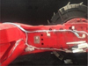 |
Fig. 13 Locations of sensors. |
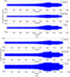 |
Fig. 14 Measured vibration response. (a) planetary gear transmission. (b) spur gear transmission. |
Comparison between measured and predicted peak amplitudes.
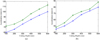 |
Fig. 15 Comparison between predicted and measured acceleration. (a) Spur gear transmission. (b) Planetary gear transmission. |
4.3 Dynamics characteristics of CUGH
4.3.1 Power spectral density of CUGH's acceleration results
The frequency analysis of the vibration response of gearbox region near planetary gear transmission is studied for obtaining the resonance characteristics of CUGH. Figure 16 shows the power spectral densities of accelerations. It can be seen that dominant frequencies of CUGH's vibration response are 950 Hz, 1250 Hz and 1400 Hz. However, these dominant frequencies are not necessarily natural frequencies of CUGH. They may be gear meshing frequencies, frequency multiplication and their coupled frequencies. Hence, natural characteristics of CUGH, which contains natural frequencies and natural vibration modes, should be analyzed for identifying whether these dominant frequencies (950 Hz, 1250 Hz and 1400 Hz) can cause resonance of CUGH.
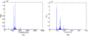 |
Fig. 16 Power spectral density (PSD). (a) 100 mm cutting depth. (b) 600 mm cutting depth. |
4.3.2 Natural characteristics of CUGH
Finite element model of CUGH has been established before, as shown in Figure 11. ANSYS finite element software is used for obtaining natural characteristics of CUGH. Figure 17 shows the natural characteristics of CUGH. It can be seen that the 15th order natural frequency 914 Hz is close to dominant frequency 950 Hz (a), the 23th order natural frequency 1248 Hz is close to dominant frequency 950 Hz (b), the 27th order natural frequency 1391 Hz is close to dominant frequency 950 Hz (c). Hence, resonance of CUGH will occur when excitation frequencies are close to dominant frequencies.
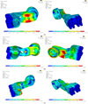 |
Fig. 17 Natural characteristics of CUGH. (a) The 15th order; (b) The 23th order; (c) The 27th order. |
4.3.3 Excitation frequencies of CUGH
The source of excitation of CUGH is gear meshing frequencies of gear transmission system and cutting forces on drum. The frequencies of cutting forces on drum are lower than 5 Hz, and impossible to cause resonance of CUGH. Hence, gear meshing frequencies and their coupling frequencies can be the source of excitation for the resonance of CUGH. Here, coupling frequencies occur due to the superposition of meshing forces in different gear transmission stages, and coupling frequencies in gear transmission system are found in the research of some scholars [29–31]. Frequency coupling can increase the number of excitation frequency and the probability of resonance for CUGH. Based on transmission system parameters provided by factory, the meshing frequencies of straight tooth gear transmission are: (115)where n and z are rotation speed of gear axis (r/min) and the number of teeth.
The meshing frequencies of planetary gear transmission are:
 (116)where za, fb, fa are teeth number of ring gear, teeth number of sun gear, rotation frequency of carrier, rotation frequency of sun gear axis.
The characteristic frequencies of cutting gearbox transmission system are shown in Table 5 .
Figure 18 shows the FFT spectrum for vibration response of gearbox region near planetary gear transmission. It can be seen that dominant frequencies − 950 Hz, 1250 Hz and 1400 Hz, are close to double frequencies and coupling frequencies of gear meshing frequencies (2 × fz2, 2 × fz2 + 2 × fm1, 2 × fz1). Dominant frequencies are close to both gear meshing frequencies and CUGH's natural frequencies. Therefore, vibration caused by gear meshing is the source of resonance of CUGH.
Characteristic frequencies of cutting gearbox.
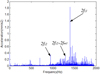 |
Fig. 18 FFT spectra for vibration response of planetary gear transmission. |
4.3.4 Influence factors of frequency coupling
The influence rules of cutting forces on gear meshing frequency coupling phenomenon in planetary and spur gear transmission are investigated in this paper. Figure 19 shows the frequency domain response of planetary transmission. It can be seen that characteristic frequencies such as fz2, 2fz2 + 2fm1, 2fz1, 2fz2 appear in the first stage of planetary transmission. There are 4 coupling frequencies when the cutting depth is 100 mm, and this number decreases to 3 and 2 when cutting depth increases to 300 mm and 600 mm. Therefore, gear meshing frequency coupling phenomenon of planetary transmission reduces with the cutting force on drum. Figure 20 shows the frequency domain response of spur gear transmission. It can be seen that more coupling frequencies than planetary gear transmission are found in spur gear transmission such as fz1, 2fz2, 2fz1, 2fz2 + 2fm1, 2fz1 + fz2. The number of coupling frequencies keeps unchanged with the increase of cutting force. Hence, cutting force can't influence gear meshing frequency coupling of spur gear transmission.
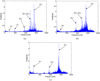 |
Fig. 19 Frequency coupling of planetary transmission. (a) 100 mm cutting depth; (b) 300 mm cutting depth; (c) 600 mm cutting depth. |
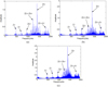 |
Fig. 20 Frequency coupling of spur gear transmission. (a) 100 mm cutting depth; (b) 300 mm cutting depth; (c) 600 mm cutting depth. |
4.3.5 Failure mechanism analysis based on dynamics results
As mentioned in Section 1 “Introduction”, fracture failure is the main and severe failure mode of CUGH. Figure 21 illustrates a typical fracture failure for CUGH. It can be seen that a large fracture occurs in planetary gear transmission part. According to the results of this paper, dominant frequencies of CUGH are 950 Hz, 1250 Hz and 1400 Hz. Gear meshing frequencies are close to dominant frequencies and can cause resonance of CUGH in terms of the study of Section 4.3.3. Mode shapes of these dominant frequencies are shown in Figure 17, and it can be seen that planetary gear transmission part is bearing both torsional shearer stress and tensile. When these stresses exceed limit, fracture failure will occur, as shown in Figure 21.
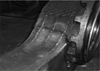 |
Fig. 21 Fracture failure in CUGH. |
5 Conclusions
-
Complete machine dynamics model for coal shearer is firstly established in this paper for obtaining external force on articulated holes (connecting part between CUGH and other parts of coal shearer) caused by complete machine vibration. Calculation model for stochastic cutting forces on drum is established as external load of both complete machine and gear transmission dynamics models. It is worth noting that stochastic cutting force model on drum in oblique cutting is firstly established in this paper.
-
Dynamics model for gear transmission system in coal shearer cutting unit gearbox is established for obtaining external force on bearing holes of CUGH caused by gear meshing. Results show that times of load application order from the most to the least is as follows: first spur gear transmission stage > second spur gear transmission stage > first planetary gear transmission stage > second planetary gear transmission stage. Forces of planetary gear transmission are larger than spur gear transmission. Dynamic response calculated by theoretical dynamics model and finite element model agrees well with measured results conducted by coal cutting experiment.
-
Dominant frequencies of CUGH are 950 Hz, 1250 Hz and 1400 Hz. They are close to both gear meshing frequencies and CUGH's natural frequencies. Therefore, vibration caused by gear meshing is the source of resonance of CUGH. Cutting forces on drum can't cause resonance.
-
Number of coupling frequencies of planetary transmission reduces with the cutting forces on drum. More coupling frequencies than planetary gear transmission are found in spur gear transmission and the number of coupling frequencies keeps unchanged with the increase of cutting forces. Hence, cutting forces can't influence gear meshing frequency coupling of spur gear transmission.
Funding
This study was funded by Chinese National Natural Science Foundation (U1708254).
Conflict of interest
The authors declare that they have no conflict of interest.
Appendix
Some constants in dynamics model for gear transmission system.
References
- China National Bureau of Statistics, Statistical Bulletin on National Economic and Social Development [M], China National Bureau of Statistics, Beijing, China, 2016 [Google Scholar]
- Q. Wang, B. Li, J. Huang, Coal mining machine and support equipment [M], China Mining University, Xuzhou, 2006, pp. 33–81 [Google Scholar]
- X. Xu, Technical status and development trend of coal mining machinery [J], Coal Zhongzhou 4, 15–16 (2005) [Google Scholar]
- Z. Wang, Causes of low reliability of mechanical system in electric traction shearer and improvement measures, Min. Mach. 43, 1–4 (2015) [Google Scholar]
- J. Zhou, L. Mi, Fault and reliability analysis of shearer rocker arm gearbox, Shenhua Sci. Technol. 9, 40–42 (2011) [Google Scholar]
- L. Zhao, X. Jin, Y. Zhao, Discrete element simulation analysis of wear characteristics for drum in coal seam with gangue, J. China Coal Soc. 38, 1–10 (2019) [Google Scholar]
- L. Zhao, X. Liu, K. Huang, Reliability analysis on the key parts of the cutting unit of shearer based on stress-strength interference theory, J. China Coal Soc. 44, 965 (2019) [Google Scholar]
- L. Zhao, J. Fan, Based on neural network reliability study of shearer's cutting part, J. Mech. Streng. 40, 869–874 (2018) [Google Scholar]
- L. Zhao, M. Zhao, X. Liu, Research on reliability of shearerrocker shell based on VP and BP neural network, J. Mech. Strength, 39, 1379–1384 (2017) [Google Scholar]
- L. Zhao, D. Fu, M. Li, The shearer rocker fault diagnosis based on virtual prototype, Mod. Manufactur. Eng. 11, 143–145 (2018) [Google Scholar]
- L. Zhao, Y. Zhao, X. Jin, P. Liu, Numerical simulation study on wear failure of helical blade in coal seam with dirt band, J. Syst. Simul. 26, 1–9 (2019) [Google Scholar]
- J. Mao, Y. Zhu, H. Chen et al., Life prediction and optimization analysis of the shearer rocker's arm transmission system, J. Mach. Des. 35, 53–55 (2018) [Google Scholar]
- J. Mao, X. Liu, H. Chen, Simulation study on the influence of coal seam inclination on the working performance of drum, J. Mech. Strength 41, 673–681 (2019) [Google Scholar]
- H. Chen, K. Zhang, J. Mao et al., Fatigue life analysis of planetary carrier of shearer cutting unit based on load reconstruction theory, J. Mech. Strength 40, 1183–1188 (2018) [Google Scholar]
- H. Chen, Y. Bai, J. Mao et al., 7-DOF nonlinear vibration analysis of shearer under condition excitation, J. Mech. Strength 39, 1–6 (2017) [Google Scholar]
- C. Liu, D. Qin, Y. Liao, Dynamic analysis for the cutting electromechanical transmission system in the long-wall shearer, J. Mech. Eng. 52, 15–19 (2016) [Google Scholar]
- Y. Yi, D. Qin, C. Liu et al., Dynamic behavior of the electromechanical transmission system of a coal shearer in transient regimes, J. Vib. Shock 37, 143–145 (2018) [Google Scholar]
- Y. Yang, H. Fan, P. Ma, Research on dynamic characteristics for longwall shearer cutting transmission system with varying cutting speed [J]. Int. J. Precis. Eng. Manuf. 18, 1131–1138 (2017) [CrossRef] [Google Scholar]
- R. Zhang, Y. Zhang, L. Zhu, et al., Vibration characteristics for the rocker arm of shearer with gear meshing excitation[J]. J. Northeast. Univ. Nat. Sci. 39, 109–112 (2018) [Google Scholar]
- Y. Zhang, R. Zhang, L. Zhu, et al., Dynamic characteristics and influence factors of a shearer's rocker arm[J]. J. Vib. Shock 37, 114–118 (2018) [Google Scholar]
- L. Lan, Z. Chenqing, R. Yafeng et al., Dynamical modeling for a gear box full-coupling system and influence analysis of housing [J]. J. Harbin Eng. Univ. 39, 561–568 (2018) [Google Scholar]
- R. Yafeng, Changshan, L. Geng et al., Influence of housing flexibility on the dynamic characteristics of gear transmission systems [J]. J. Vib. Shock 36, 85–91 (2017) [Google Scholar]
- H. Chaoxia, C. Lehao, L. Lan, Dynamic response analysis of planetary gear transmission system coupled with gearbox vibrations [J]. J. South China Univ. Technol. Nat. Sci. 43, 128–134 (2015) [Google Scholar]
- W. He, J. Peng, Study on dynamic characteristic analysis of shearer cutting part [J]. Ind. Mining Automat. 40, 65–68 (2019) [Google Scholar]
- X. Li, H. Ge, Mathematical model of stochastic pick loads for a continuous miner [J]. Chin. J. Constr. Mach. 4, 262–264 (2006) [Google Scholar]
- M. Kubur, A. Kahraman, D.M. Zini, Dynamic analysis of a multi-shaft helical gear transmission by finite elements: model and experiment [J]. J. Vib. Acoust. 126, 398–402 (2004) [Google Scholar]
- C. Liu, Design basis for long wall coal shearer [M], Press of China University of Mining and Technology, Xuzhou, 2003 [Google Scholar]
- R.G. Parker, J. Lin, Mesh phasing relationships in planetary and epicyclic gears [J]. J. Mech. Des. 126, 365–368 (2004) [CrossRef] [Google Scholar]
- L. Hui, C. Zhongchang, X. Changle, Frequency coupling and dynamic characteristics of nonlinear meshing force for two-stage planetary gears [J]. J. Vib. Shock 34, 13–18 (2015) [Google Scholar]
- J. Wei, A. Zhang, D. Qin et al., A coupling dynamics analysis method for a multistage planetary gear system [J]. Mech. Mach. Theory 110, 27–49 (2017) [Google Scholar]
- L. Walha, T. Fakhfakh, M. Haddar, Nonlinear dynamics of a two-stage gear system with mesh stiffness fluctuation, bearing flexibility and backlash [J]. Mech. Mach. Theory 44, 1058–1069 (2009) [Google Scholar]
Cite this article as: R. Zhang, Y. Zhang, Dynamic characteristics for coal shearer cutting unit gearbox housing, Mechanics & Industry 21, 211 (2020)
All Tables
All Figures
|
Fig. 1 Long wallmining(National Energy Mining Equipment Laboratory of China). |
| In the text | |
|
Fig. 2 Cutting unit gearbox housing (CUGH). |
| In the text | |
|
Fig. 3 MG500-1180/WD coal shearer. |
| In the text | |
|
Fig. 4 Complete machine dynamics model of coal shearer. |
| In the text | |
|
Fig. 5 Force diagram of the cutting drum. |
| In the text | |
|
Fig. 6 Picks arrangement on cutting drum of MG500-1180/WD. |
| In the text | |
|
Fig. 7 Cutting forces on drum of MG500-1180/WD. (a) Cutting resistance (straight line cutting); (b) forward resistance(straight line cutting); (c) torque (straight line cutting); (d) torque (oblique cutting); (e) cutting resistance (oblique cutting); (f) forward resistance (oblique cutting). |
| In the text | |
|
Fig. 8 Dynamic forces on articulated holes. (a) X direction (straight line cutting); (b) Y direction (straight line cutting); (c) X direction (oblique cutting); (d) Y direction (oblique cutting). |
| In the text | |
|
Fig. 9 Gear transmission system. |
| In the text | |
|
Fig. 10 Force on bearing holes of CUGH. (a) X direction of first spur gear transmission stage. (b) Y direction of first spur gear transmission stage. (c) X direction of second spur gear transmission stage. (d) Y direction of second spur gear transmission stage. (e) X direction of first planetary gear transmission stage. (f) Y direction of first planetary gear transmission stage. (g) X direction of second planetary gear transmission stage. (h) Y direction of second planetary gear transmission stage. |
| In the text | |
|
Fig. 11 FE model for CUGH. |
| In the text | |
|
Fig. 12 Coal cutting process. |
| In the text | |
|
Fig. 13 Locations of sensors. |
| In the text | |
|
Fig. 14 Measured vibration response. (a) planetary gear transmission. (b) spur gear transmission. |
| In the text | |
|
Fig. 15 Comparison between predicted and measured acceleration. (a) Spur gear transmission. (b) Planetary gear transmission. |
| In the text | |
|
Fig. 16 Power spectral density (PSD). (a) 100 mm cutting depth. (b) 600 mm cutting depth. |
| In the text | |
|
Fig. 17 Natural characteristics of CUGH. (a) The 15th order; (b) The 23th order; (c) The 27th order. |
| In the text | |
|
Fig. 18 FFT spectra for vibration response of planetary gear transmission. |
| In the text | |
|
Fig. 19 Frequency coupling of planetary transmission. (a) 100 mm cutting depth; (b) 300 mm cutting depth; (c) 600 mm cutting depth. |
| In the text | |
|
Fig. 20 Frequency coupling of spur gear transmission. (a) 100 mm cutting depth; (b) 300 mm cutting depth; (c) 600 mm cutting depth. |
| In the text | |
|
Fig. 21 Fracture failure in CUGH. |
| In the text | |
Current usage metrics show cumulative count of Article Views (full-text article views including HTML views, PDF and ePub downloads, according to the available data) and Abstracts Views on Vision4Press platform.
Data correspond to usage on the plateform after 2015. The current usage metrics is available 48-96 hours after online publication and is updated daily on week days.
Initial download of the metrics may take a while.