| Issue |
Mechanics & Industry
Volume 22, 2021
|
|
|---|---|---|
| Article Number | 23 | |
| Number of page(s) | 10 | |
| DOI | https://doi.org/10.1051/meca/2021025 | |
| Published online | 09 April 2021 | |
Regular Article
Influence of rotational speed and torque on meshing efficiency of double helical gear transmission system
School of Mechanical Engineering, University of Jinan, Jinan 250022, PR China
* e-mail: me_wangc@ujn.edu.cn
Received:
2
September
2020
Accepted:
15
March
2021
The accuracy of gear meshing efficiency model is the key to study the influence factors of gear meshing efficiency. Experiment is an effective method to verify the theory model. Therefore, the acquisition of experimental value of gear meshing efficiency is particularly important. Taken double helical gears as the research object, on the analysis of a large number of experimental data, the experimental value of gear meshing efficiency for double helical gears are calculated and then the influence of rotational speed and torque on meshing efficiency of double helical gears is studied. Firstly, the calculation method of transmission efficiency for experimental value in different layout of gear test-rigs with closed power flow is summarized. Secondly, the calculation method of meshing efficiency for experimental value in gear test-rig with closed power flow is introduced. Thirdly, the calculation method of load-dependent bearing loss is given. Finally, the experimental value of meshing efficiency for double helical gears is calculated and the influence of rotational speed and torque on meshing efficiency of double helical gears is obtained, which lays a theoretical foundation for the further improvement of the transmission efficiency of double helical gears.
Key words: Meshing efficiency / transmission efficiency / double helical gears / experiment / test-rig with closed power flow
© C. Wang, published by EDP Sciences 2021
 This is an Open Access article distributed under the terms of the Creative Commons Attribution License (https://creativecommons.org/licenses/by/4.0), which permits unrestricted use, distribution, and reproduction in any medium, provided the original work is properly cited.
1 Introduction
Nowadays, the world is facing serious problems such as resource shortage and environmental pollution. Energy conservation and consumption reduction have become an important task of sustainable development. Increasing the efficiency of mechanical products, especially high-power transmission devices, as an effective way to achieve energy saving and consumption reduction, has attracted more and more attention. As one of the most widely used transmission mechanisms, researchers have done a lot of work on the transmission efficiency of gears. Wang [1,2] used the constraint analysis and the virtual power theory to establish the efficiency model of closed differential double helical gear train and planetary gear transmission system, respectively. Wang [3] proposed a calculation method of transmission efficiency for complex planetary gear train by the hypergraph-based method. The relationship between input speed/input power/lubrication condition and transmission efficiency were analyzed. Simon [4] proposed a multi-objective optimization method for hypoid gears. Among optimal objectives, the mechanical efficiency of gear pair was considered.
Kim [5] took weight, efficiency and noise of helical gear as the objectives, a macro geometry was optimized and good effect was obtained. Paschold [6] proposed a calculation method of load-dependent and no-load losses, the efficiency of worm gears was analyzed. Oehler [7] analyzed the relationship among conditions, power dissipation and temperature. On the basis, the efficiency and temperature of gearbox can be estimated for arbitrary load. Wan [8] proposed a calculation method of transmission efficiency for double-arc bevel gear nutation transmission system. The nutation gear ratio and speed ratio of two power sources affected the transmission efficiency. Lin [9] proposed a calculation method of meshing efficiency for curve-face gear pair and factors related to meshing efficiency were discussed.
The composition of power losses of gear transmission is shown in Figure 1. It includes: windage loss, swinging oil loss, bearing loss and gear meshing power loss. The calculation method of gear transmission efficiency is to calculate the above quantities separately, and then add them together to get the gear transmission efficiency. Because the calculation of windage loss, swinging oil loss, bearing loss is more complicated and the gear meshing power loss accounts for a large proportionamong them, in order to simplify, the meshing efficiency is usually used to replace transmission efficiency in many cases. Experiments are an effective means to verify theory. However, the test data can directly calculate gear transmission efficiency rather than gear meshing efficiency. Therefore, how to calculate the experimental value of meshing efficiencyis particularly important. Xu [10] gave a calculation method of gear meshing efficiency for test data according to the fact that windage loss and swinging oil loss have nothing to do with load. Wang [11] further developed the method to make it more widely used including the calculation of meshing efficiency in power closed type gear test-rig, the calculation of meshing efficiency inpower open type gear test-rig and the calculation of meshing efficiency ingear test-rig with various transmission ratios.
Research on the influence factors of meshing efficiency is one of the core contents of improving gear meshing efficiency. At present, most of the research focuses on the factors affecting the gear transmission efficiency. Chen [12] analyzed the effect of power split on transmission efficiency under different speed, which provided theoretical basis for transmission ratio distribution and structure design of planetary gear train. Thamba [13] studied the effect of linear tip relief modification on transmission efficiency of spur gear. By the linear tip relief modification, the transmission errors were obviously reduced.
Double helical gears have been widely used in high power transmission devices including warship, oil pumping machine, rolling mill and etc. High transmission efficiency/meshing efficiency is of great significance for improving their transmission performance. Wang [14] proposed a method for calculating the sliding friction power losses of double helical gears by tooth contact analysis technology and loaded tooth contact analysis technology. The meshing efficiency of gears is affected not only by design parameters, but also by machining accuracy, lubrication conditions and working conditions, etc. At present, for double helical gears, there is still a lack of detailed and in-depth study.
Based on the above analysis, taken double helical gears as the research object, on the analysis of a large number of experimental data, the meshing efficiency of double helical gears are calculated and then the influenceof rotational speed and torque on meshing efficiency of double helical gears is obtained, which lays a theoretical foundation for the further performance improving double helical gearsmeshing efficiency. The flow diagram for this paper is shown in Figure 2.
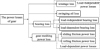 |
Fig. 1 The composition of power losses of gear transmission. |
 |
Fig. 2 The flow diagram for the calculation of experimental value of meshing efficiency for double helical gears and the influence of rotational speed and torque. |
2 The calculation method of transmission efficiency for experimental value in different layout of gear test-rigs with closed power flow
Common layout of gear test-rig with closed power flow and formula of gear transmission efficiency for experimental value are shown in Table 1 [15]. It is assumed that the test gearbox and the reaction gearbox are identical, including specifications, models, manufacturing processes, manufacturing levels and forward and reverse transmission efficiency. The condition ① and ② correspond to Figure 3a, the condition ③ and ④ correspond to Figure 3b. Their formulas of transmission efficiency can be also respectively represented as equations (1) and (2). In Table 1, P1 is the transmission power of gear 1, P2 is the transmission power of gear 2, P3 is the transmission power of gear 3, P4 is the transmission power of gear 4, PS is the power on the loader shaft, which is equivalent to T2
n2 in formula (1) and (2), PM is the supplementary power by the motor, which is equivalent to T1
n1 in formula (1) and (2), η is the transmission efficiency of test gear. (1)
(1)
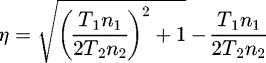 (2)
Where, η is the transmission efficiency of test gear, T1 is the torque measured by the torque meter 1, n1 is the revolution measured by the revolution meter 1, T2 is the torque measured by the torque meter 2, n2 is the revolution measured by the revolution meter 2.
(2)
Where, η is the transmission efficiency of test gear, T1 is the torque measured by the torque meter 1, n1 is the revolution measured by the revolution meter 1, T2 is the torque measured by the torque meter 2, n2 is the revolution measured by the revolution meter 2.
Common layout of gear test-rig with closed power flow and formula of gear transmission efficiency.
 |
Fig. 3 Schematic diagram of gear transmission efficiency test-rig with closed power flow. (a) Motor and loader are on the same axis (b) Motor and loader are on the different axis. |
3 The calculation method of meshing efficiency for experimental value in gear test-rig with closed power flow
Figure 1 shows the composition of power losses of gear transmission, which includes windage loss, swinging oil loss, bearing loss and gear meshing power loss. Among them, windage loss, swinging oil loss and partial bearing loss belong to the load-independent power losses and are only related to rotational speed of gear. Under the same rotational speed and input power, the transmission efficiency ηS of test gear under no-load and transmission efficiency ηT of test gear under loadedconditions are calculated according to equations (3) and (4), respectively. They are put in equation (5), the meshing efficiency ηM of test gear can be obtained. The power loss PS including windage loss and swinging oil loss and the load-independent bearing lossPBI are very complicated, in the proposed method, they do not need to calculate. The calculation of ηT and ηS come from the equations (1) or (2) by the measured data. (3)
(3)
 (4)
(4)
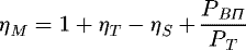 (5)where, ηS is the transmission efficiency of test gear under no-load, ηT is the transmission efficiency of test gear under loaded conditions, ηM is the meshing efficiency for test gear in gear test-rig with closed power flow, PS is the windage loss and swinging oil loss, PBI is the load-independent bearing loss, PBII is the load-dependent bearing loss, PT is the total input power. The calculation of ηT and ηS come from the equations (1) or (2).
It should be pointed out that in this section, the calculation method of meshing efficiency for experimental value in gear test-rig with closed power flow is only given. More detailed derivation process can be found in [10] and [11].
4 The calculation of load-dependent bearing loss
According to the existing formula (10), the calculation of load-dependent bearing loss can be represented as (6)
(6)
Where, PBII is the load-dependent bearing loss, µbi (i = 1, 2) is the friction coefficient of bearing, Wbi (i = 1,2) is the radial load applied to the bearing, dborei (i = 1, 2) is the inner diameter of bearing, n is the revolution speed of gear. The determination of µbi and dborei are related to the type of bearing selected. The determination of n is related to the working condition. The calculation method of Wbi will be introduced below.
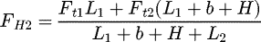
The force analysis of double helical gear shaft is shown in Figure 4. The following equations can be obtained. (7)
(7)
 (8)
(8)
 (9)
(9)
 (10)
(10)
 (11)
(11)
 (12)
(12)
 (13)
(13)
 (14)
(14)
 (15)
(15)
 (16)
(16)
 (17)
(17)
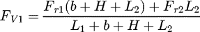
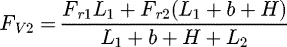
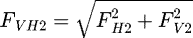 (18)where, Fni (i = 1, 2) is the normal force, Fti (i = 1, 2) is the circumferential force, Fri (i = 1, 2) is the radial force, Fai (i = 1, 2) is the axial force, FHi (i = 1, 2) is the horizontal supporting force, FVi (i = 1, 2) is the vertical supporting force, FVHi (i = 1, 2) is the resultant force of horizontal and vertical supporting force, which is the radial load Wbi applied to the bearing, b is the tooth width, H is the length of middle connecting cylinder of double helical gear, L1 is the length from center of left bearing to midpoint of left tooth width, L2 is the length from center of right bearing to midpoint of right tooth width.
Where, Mti (i = 1, 2) is the torque on the shaft produced by the circumferential force, Mai (i = 1, 2) is the bending moment on the shaft produced by the axial force.
 |
Fig. 4 Force analysis of double helical gear shaft. |
5 Experimental value calculation of meshing efficiency for double helical gears and the influence of rotational speed and torque on meshing efficiency of double helical gears
The contents of this section include the introduction of experimental double helical gears, test-rig for transmission efficiency of double helical gears with closed power flow, experimental conditionand the influence analysis of rotational speed and torque on meshing efficiency of double helical gears.
5.1 Experimental double helical gears
The parameters of experimental double helical gears are shown in Table 2. The drawing of experimental pinion and gear is shown in Figure 5. The measurement curve of experimental pinion and gear are shown in Figures 6–9, respectively. According to the design requirements and the measured curve, the pinion machining precision is 4 grades. Similarly, the gear machining precision is also 4 grades.
Parameters of experimental double helical gears.
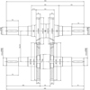 |
Fig. 5 Drawing of experimental pinion and gear. |
 |
Fig. 6 Profile measurement curve of pinion. |
 |
Fig. 7 Helix measurement curve of pinion. |
 |
Fig. 8 Profile measurement curve of gear. |
 |
Fig. 9 Helix measurement curve of gear. |
5.2 Test-rig for transmission efficiency of double helical gears with closed power flow
The schematic diagram of test-rig for transmission efficiency of double helical gears with closed power flow is shown in Figure 10. Test-rig for transmission efficiency of double helical gears with closed power flow is shown in Figure 11. The rotational speed range of torque and speed sensor is 0–1400 min−1, torque range of torque and speed sensor is 0–500 Nm, accuracy of torque and speed sensor is ±0.05% fs. The test-rig is correspond to Figure 3a, therefore, the calculation of transmission efficiency comes from formula (1).
 |
Fig. 10 The schematic diagram of test-rig for transmission efficiency of double helical gears with closed power flow. |
 |
Fig. 11 Test-rig for transmission efficiency of double helical gears with closed power flow. |
5.3 Experimental condition
The load is applied gradually. The applied torques are 0, 52, 140, 245 and 345 Nm, respectively. When the applied torque is stable, the speed increases step by step according to 30 r/min. For example, when the applied torque is 0 Nm, the applied speed are 120, 150, …, 870 in turn, When the applied torque is 52 Nm, the applied speed are 120, 150, …, 870 in turn and so on. The gearbox is lubricated by oil injection and naturally dissipates heat. After reaching the thermal balance, the speed and torque are measured and recorded. Experimental condition are shown in Table 3.
Experimental condition.
5.4 Influence of rotational speed and torque on transmission efficiency of double helical gears
Under the same working condition, a large number of rotational speed and torque experimental data are measured. Obviously unreasonable data are excluded. Theload-dependent bearing loss is calculated according to the formulas (6)–(18). The transmission efficiencyfor test gear in gear test-rig with closed power flow under no-load and load are calculated according the formulas (3) and (4). The meshing efficiency of double helical gears is calculated according to the formula (5). Because the rotational speed and torque measured data are within a certain range, in order to eliminate measurement error, the average values of meshing efficiency of double helical gears on same working condition are calculated. By Matlab soft, the measured data are plotted as curves. The average values of meshing efficiency of double helical gears on different working condition are marked with symbols ∘, ⊲, ⊳, Δ, respectively. The relationship curve between rotational speed/torque and meshing efficiency of double helical gears is shown in Figure 12. The torque of 52, 140, 245 and 345 Nm in Figure 12 are the average torque on same working condition.
From Figure 12, the following conclusions can be obtained:
-
With the increase of rotational speed, the meshing efficiency of double helical gears decreases. One of the reasons for this is that the increase of relative sliding velocity leads to the increase of sliding friction power loss. It can be easily found under torque 52, 140, 245 and 345 Nm, the connection line direction of average values of meshing efficiency for double helical gears are all slanted up to the left;
-
With the increase of torque, the meshing efficiency of double helical gears increase. One of the reasons for this is that total power increases while the load-independent power losses such as wind loss and oil agitation loss do not increase with the increase of load. Under different torques, the size order of meshing efficiency is as follows: η52 < η140 < η245 < η345;
-
When the torque is small, the influence of rotational speed on meshing efficiency is obvious. With the increase of torque, the influence of rotational speed on meshing efficiency becomes weaker. The connection line slope of average values of meshing efficiency for double helical gears under 52 Nm is the largest, the connection line slope under 140 Nm is second, the connection line slope under 245 Nm is third and the connection line slope under 345 Nm is the smallest;
-
When the load is very small, the meshing efficiency is very low. It is very obvious that the average values of meshing efficiency for double helical gears under 52 Nm is lower than 0.94, while the average values of meshing efficiency for double helical gears under 345 Nm is higher than 0.98.
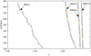 |
Fig. 12 Relationship curve between rotational speed/torque and meshing efficiency of double helical gears. |
6 Conclusion
Gear meshing efficiency is an important component of gear transmission efficiency. Usually, the test data can directly calculate gear transmission efficiency rather than gear meshing efficiency. Therefore, how to calculate the experimental value of meshing efficiency is particularly important. In addition, the research on the influence factors of meshing efficiency is one of the core contents of improving gear meshing efficiency. Therefore, taken double helical gears as the research object, on the analysis of a large number of experimental data, the experimental value of gear meshing efficiency for double helical gears are calculated and then the influence of rotational speed and torque on meshing efficiency of double helical gears is obtained.
-
Aimed at different layout of gear test-rigs with closed power flow, the calculation method of transmission efficiency for experimental value is summarized.
-
According to the fact that windage loss, swinging oil loss and partial bearing loss belong to the load-independent power losses and are only related to rotational speed of gear, the existing calculation method of meshing efficiency for experimental value in gear test-rig with closed power flow is introduced.
-
According to the structural characteristics of double helical gears, the calculation method of load-dependent bearing loss is given.
-
On the analysis of a large number of experimental data, the experimental value of gear meshing efficiency for double helical gears are calculated and then the influence of rotational speed and torque on meshing efficiency of double helical gears is obtained. The relationship between rotational speed and meshing efficiency is inversely proportional. The relationship between torque and meshing efficiency is proportional. The influence of rotational speed on transmission efficiency is very obvious under small torque. With the increase of torque, the influence of rotational speed on meshing efficiency becomes weaker. The meshing efficiency is very low when the torque is very small. Therefore, for high precision gears, transmission under small load should be avoided as far as possible.
This work is a further application for the existing theory of calculation method of meshing efficiency for experimental value through a large amount of experimental data, which lays a theoretical foundation for the further improvement of the transmission efficiency of double helical gears.
Conflict of interest
The author declared no potential conflicts of interest withrespect to the research, authorship, and/or publication of this article. The author also state that I have full control of all primary data and that I agree to allow the journal to review my data if requested.
Acknowledgments
The author wishes to acknowledge the financial support of Natural Science Foundation of Shandong Province (Grant No. ZR2020ME118) during the course of this investigation. The author would also like to thank the editor and anonymous reviewers for their suggestions for improving the paper.
References
- C. Wang, The effect of planetary gear/star gear on the transmission efficiency of closed differential double helical gear train, Proceedings of the Institution of Mechanical Engineers 234 , 4215–4223 (2020) [Google Scholar]
- C. Wang, High power density design for planetary gear transmission system, Proceedings of the Institution of Mechanical Engineers, Part C: Journal of Mechanical Engineering 233 , 5647–5658 (2019) [Google Scholar]
- W. Yun et al., Power flow and efficiency analysis of high-speed heavy load herringbone planetary transmission using a hypergraph-based method, Applied Sciences-Basel 10 , 5849 (2020) [Google Scholar]
- V.V. Simon, Multi-objective optimization of hypoid gears to improve operating characteristics, Mechanism and Mechanical Theory 146 , UNSP 103727 (2020) [Google Scholar]
- S. Kim, S. Moon, J. Sohn, Macro geometry optimization of a helical gear pair for mass, efficiency, and transmission error, Mechanism and mechanical theory 144 , UNSP 103634 (2020) [Google Scholar]
- C. Paschold et al., Efficiency and heat balance calculation of worm gears, Forschungimingenieurwesen Engineering Research 84 , 115–125 (2020) [Google Scholar]
- M. Oehler, B. Sauer, B. Magyar, Efficiency of worm gear drives under transient operating conditions, Journal of Tribology Ttransactions of the ASME 141 , 122201 (2019) [Google Scholar]
- N. Wan, L. Yao, Efficiency modelling and analysis for a novel double-arc bevel gear nutation transmission system for pure electric vehicles, Forschungimingenieurwesen Engineering Research 83 , 393–399 (2019) [Google Scholar]
- C. Lin et al., Calculation and analysis of meshing efficiency of composite motion of the curve-face gear pair, Tranasctions of the Canadian Society for Mechanical Engineering 43 , 431–441 (2019) [Google Scholar]
- H. Xu, N.E. Anderson, D.G. Maddock, A. Kahraman, Prediction of mechanical efficiency of parallel-axis gear pairs, Journal of Mechanical Design 129 , 58–68 (2007) [Google Scholar]
- C. Wang, S. Wang, G. Wang, A method for calculating gear meshing efficiency by measured data fromgear test machine, Measurement 119 , 97–101 (2018) [Google Scholar]
- X. Chen et al., Study on power split characteristics of planetary multistage face gear transmission device and its effect to drive efficiency under variable speed working condition, Mechanical Sciences 11 , 173–182 (2020) [Google Scholar]
- N.B. Thamba et al., Study of effect of linear tip relief modification in power transmission efficiency of spur gears, Archives of Acoustics 45 , 271–282 (2020) [Google Scholar]
- C. Wang, C. Gao, H. Jia, Power losses of sliding friction based onmeshing characteristics of double helical gears, Journal of Central South University (Science and Technology) 43 , 2173–2178 (2012) [Google Scholar]
- C. Wang, Research on the installation position of motor and loader in the gearmeasuring test‑rig with close power, Journal of the Brazilian Society of Mechanical Sciences and Engineering 40 , 504–513 (2018) [Google Scholar]
Cite this article as: C. Wang, Influence of rotational speed and torque on meshing efficiency of double helical gear transmission system, Mechanics & Industry 22, 23 (2021)
All Tables
Common layout of gear test-rig with closed power flow and formula of gear transmission efficiency.
All Figures
|
Fig. 1 The composition of power losses of gear transmission. |
| In the text | |
|
Fig. 2 The flow diagram for the calculation of experimental value of meshing efficiency for double helical gears and the influence of rotational speed and torque. |
| In the text | |
|
Fig. 3 Schematic diagram of gear transmission efficiency test-rig with closed power flow. (a) Motor and loader are on the same axis (b) Motor and loader are on the different axis. |
| In the text | |
|
Fig. 4 Force analysis of double helical gear shaft. |
| In the text | |
|
Fig. 5 Drawing of experimental pinion and gear. |
| In the text | |
|
Fig. 6 Profile measurement curve of pinion. |
| In the text | |
|
Fig. 7 Helix measurement curve of pinion. |
| In the text | |
|
Fig. 8 Profile measurement curve of gear. |
| In the text | |
|
Fig. 9 Helix measurement curve of gear. |
| In the text | |
|
Fig. 10 The schematic diagram of test-rig for transmission efficiency of double helical gears with closed power flow. |
| In the text | |
|
Fig. 11 Test-rig for transmission efficiency of double helical gears with closed power flow. |
| In the text | |
|
Fig. 12 Relationship curve between rotational speed/torque and meshing efficiency of double helical gears. |
| In the text | |
Current usage metrics show cumulative count of Article Views (full-text article views including HTML views, PDF and ePub downloads, according to the available data) and Abstracts Views on Vision4Press platform.
Data correspond to usage on the plateform after 2015. The current usage metrics is available 48-96 hours after online publication and is updated daily on week days.
Initial download of the metrics may take a while.