| Issue |
Mechanics & Industry
Volume 18, Number 6, 2017
|
|
|---|---|---|
| Article Number | 603 | |
| Number of page(s) | 20 | |
| DOI | https://doi.org/10.1051/meca/2016063 | |
| Published online | 02 February 2018 | |
Regular Article
Performance of two-lobe hole-entry hybrid journal bearing system under the combined influence of textured surface and couple stress lubricant
Tribology Laboratory, Department of Mechanical and Industrial Engineering, Indian Institute of Technology Roorkee,
Roorkee
247667, India
* e-mail: This email address is being protected from spambots. You need JavaScript enabled to view it.
Received:
15
July
2016
Accepted:
5
November
2016
Abstract
Textured surface in journal bearings is becoming an important area of investigation during the last few years. Surface textures have the shapes of micro-dimple with a small diameter and depth having order of magnitude of bearing clearance. This paper presents the influence of couple stress lubricant on the circular and non-circular hole-entry hybrid journal bearing system and reports the comparative study between the textured and non-textured circular/non-circular hybrid journal bearing system. The governing Reynolds equation has been modified for the couple stress lubricant flow in the clearance of bearing and journal. The FEM technique has been applied to solve the modified Reynolds equation together with restrictor flow equation. The numerically simulated results indicate that the influence of couple stress lubricant is significantly more in textured journal bearing than that of non-textured journal bearing. Further, it has been observed that the textured two-lobe (δ = 1.1) hybrid journal bearing lubricated with couple stress lubricant provides larger values of fluid film stiffness coefficients and stability threshold speed against other bearings studied in the present paper.
Key words: non-recessed hybrid journal bearing / two-lobe bearing / couple stress lubricant / FEM technique / surface texture
© AFM, EDP Sciences 2017
1 Introduction
Circular fluid film journal bearings usually suffer from fluid induced instability in terms of oil-whirl or oil-whip phenomena at high speed applications. It produces large self-excited vibrations and may even damage the bearing system [1]. In order to overcome these problems, non-circular journal bearings were developed by researchers and bearing designers. The simplest configurations of the non-circular fluid film journal bearings available are a two-lobe, three-lobe and four-lobe journal bearing configurations. They are characterized by their number of lobes, bearing aspect ratio and preload factor or offset factor. In the recent years most of the research activities both experimental as well as theoretical have been carried out related to performance of non-circular bearings in their research works. Pinkus et al. [2,3] studied the influence of various geometric and operating parameters on the non-circular journal bearing. They computed the load carrying capacity and power losses of elliptical journal bearing with the help of FDM numerical technique. Goenka and Booker [4] reported the effect of surface ellipticity on dynamically loaded circular bearing and optimized the bearing shape on the basis of maximizing the minimum fluid film thickness. Malik [5] computed the theoretical analysis of bearing characteristics for different configurations of two-lobe bearings. It was observed that the two-lobe bearing provides consistently better dynamic performance as compared to elliptical and offset-halves bearings. Further, Crosby [6] determined the thermodynamic solution of a finite two-lobe journal bearing and obtained the pressure and temperature distributions by solving the governing Reynolds equation and energy equation simultaneously. The theoretical and experimental comparison of dynamic coefficients for three-lobe bearing was presented by Kostrzewsky et al. [7]. They found a good agreement between theoretical and experimental dynamic coefficients with in lower range of Sommerfeld numbers. Sharana Basavaraja et al. [8] studied the influence of roughness on the performance of a misaligned two-lobe hole-entry hybrid journal bearing. They concluded that the roughened journal bearing gives the partial compensation to the effect of bearing misalignment on the value of minimum fluid film thickness especially with longitudinally surface roughness pattern. Sharma and Kushare [9] numerically analyzed the effect of surface roughness on a non-circular (two-lobe) hybrid journal bearing performance. They showed that the performance of journal bearing is significantly affected by orientation of roughness. They also concluded that the longitudinal roughness pattern improves the fluid film stiffness and damping coefficients of journal bearings.
Surface roughness is of great importance in lubrication studies as it influences friction and wear to a great extent [10]. In hydrodynamic lubrication, since the surfaces are fully separated, the surface topography at the nanometer scale is usually considered to have no influence when films of few micrometers are developed in the contact zone. The surface topography needs to be at the scale of the fluid film in order to have a noticeable influence on quantities such as pressure, friction and flow of the lubricant. Texturing is a way to control the surface topography with great accuracy. Further, the surface texture can be understood as the repetition of identical shapes along the surfaces. The presence of certain textured features is known to may benefit some lubricant systems by acting as micro-reservoirs, storing and providing the fluid directly to the contact zone. The use of a textured bearing system has been found to be more demanding due to its advantageous features such as low value of friction, higher load carrying capacity, decreasing surface damages and increasing service life of bearing [11,12]. In the recent year, many bearing designers focused on the influence of surface texture in the fluid film journal bearing system. Etsion et al. [13] investigated experimentally of the effects of surface texture on the performance of parallel thrust bearing. They reported the influence of dimple geometry on the performance of bearing by providing a series of dimples on surface of parallel thrust bearing. Further, it has been noticed that the optimized texturing parameters may help to enhance the hydrodynamic action. Siripuram and Stephens [14] studied the influence of different types of microasperities for both protruding and recessed asperities with constant height. They showed that the value of friction coefficient is independent to the types of asperity profiles and orientation, but very sensitive to the size of aperities and side leakage greatly depends on asperity profile, orientation and size. Cupillard et al. [15,16] established the mechanism for the pressure build up in converging gap due to introducing the texture profiles on the bearing surfaces. The authors analyzed the effect of dimples on the bearing performance for different depths of dimples and convergence ratios. They reported that dimples produce significant changes in the load carrying capacity for low convergence ratios k = 0.1 and k = 0.2, where the gain goes up to 74% and 32%, respectively.
Recently, Kango et al. [17] studied the influence of different types of dimples on the performance of hydrodynamic journal bearing. They concluded that the use of surface texturing on the surface of journal bearing enhances the load carrying capacity as well as reduces the friction coefficient. Influence of lubricant inertia in the textured bearing was analyzed by Syed and Sarangi [18]. They also studied the effect of dimple orientation on the performance of unit dimple slider thrust bearing. Their results showed that texture shape and size plays a vital role in the improvement of lubrication performance.
Due to the rapid technological developments in the recent decade, the bearings are required to be operated with improved lubricants. To improve the properties of lubricant, i.e., viscosity index, resistance to oxidation and volatility, etc., some polymer additives are added by tribologists and lubricant engineers. Due to the addition of these additives, lubricant behaves as a non-Newtonian lubricant [19]. The couple stress lubricant is one case of non-Newtonian lubricant, which contains the long-chain polymer molecules. The special feature of couple stress lubricant is that the stress tensor is anti-symmetric and their flow behaviour cannot be anticipated by the classical Newtonian hypothesis. In the year 1966, Stokes [20] developed the theory of couple stress with consideration of the effects of particle sizes. This theory is based on the generalization of classical theory of lubricants by accounting for the effects of anti-symmetrical stresses, couple stresses and body couples. It is proposed that a linearized constitutive equation for the force and couple stresses. Later, Stokes [21] derived the expressions for velocity and pressure distributions for creeping flow past a sphere. It was indicated that the value of drag increases with couple stresses and the effect of couple stresses is equivalent to an apparent increase in the viscosity.
Further, many investigators used the couple stress fluid theory to analyze the effect of squeeze film behaviour [22–26]. It was concluded that the squeeze film characteristics are significantly affected in the presence of couple stresses. Ramanaiah and Sarkar [22] presented the performance of slider bearings lubricated by fluids with couple stress. They derived analytical expressions for the load carrying capacity, frictional force and the centre of pressure. They observed that the load carrying capacity increases and frictional coefficient decreases with increasing the couple stress parameter. A study by Lin [23,24] deals with the influence of couple stress lubricant on the dynamic characteristics of journal bearing system. It was found that the couple stress lubricant gives the largest values of fluid film stiffness and damping characteristics as compared to Newtonian lubricants. It was also observed that for the applied external loads corresponding to the eccentricity ratio ϵ ≤ 0.7, the rotor bearing operated with couple stress fluids under a small disturbance gives more stability than Newtonian lubricant. Ma et al. [25] investigated the behaviour of dynamically loaded journal bearings lubricated with couple stress fluids. They revealed that the couple stress fluids lubrication enhances the bearing performance under dynamic loads. Further, it was also reported that the lubricants with couple stresses increase the value of fluid film pressure and the attitude angle as well as reduce the friction coefficient as compared to Newtonian lubricant. Crosby and Chetti [26] studied the effect of couple stress lubricant behaviour on the performance of two-lobe journal bearing. They concluded that the use of couple stress lubricant improved the stability of the bearing against a bearing operated with Newtonian lubricant.
A thorough review of the published literature pertaining to the journal/thrust bearing system reveals that the textured surface significantly enhances the performance of bearing. To the best of authors knowledge, a very few researchers focused their studies on the influence of surface texture on the performance of hybrid journal bearing system. Thus, it was felt more work is required that can emphasize the influence of surface texture in the area of hybrid journal bearings to provide the much needful information for the design process. However, there is no study in the literature reported so far to deal with the influence of couple stress lubricant on the performance of textured two-lobe hole-entry hybrid journal bearing system. Thus, the present work is planned to bridge this gap in the literature and to study the performance analysis of textured two-lobe hole-entry journal bearing lubricating with couple stress lubricant. The textured surfaces have been provided circumferentially on the front of each hole of bearing land area. In this study, the circular and non-circular bearing profiles are differentiating by using the non-dimensional offset factor (δ). Further, the influence of couple stress lubricant has been accounted for by defining a couple stress parameter  . The geometry of a two-lobe textured hole-entry hybrid journal bearing is presented in Figures 1–3.
 |
Fig. 1 Two-lobe hole-entry hybrid journal bearing system. |
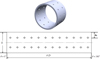 |
Fig. 2 Non-textured hole-entry journal bearing configuration. |
 |
Fig. 3 Textured hole-entry journal bearing configuration. |
2 Analysis
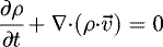
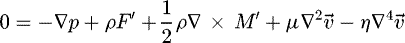
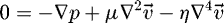
The momentum and continuity equations for the lubricant with couple stresses proposed by Stokes are given as [20,27]
 (1)
(1)
 (2)
(2)
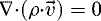
For the steady state flow of incompressible fluids,  ;
;  , equations (1) and (2) reduce to
 (3)
(3)
 (4)
(4)
By neglecting the body forces and moments, the momentum equation (3) is further reduced to
 (5)
(5)
The velocity and pressure component for two-dimensional flow of lubricant are expressed as [27,28]
 (6)
(6)
 (7)
(7)
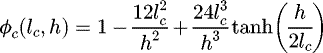
By incorporating the appropriate boundary conditions in equations (6) and (7) and with the help of continuity equation of flow, the modified Reynolds equation is obtained as follows [29,30]:
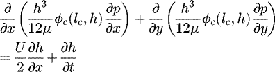 (8)
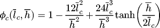
where ϕc(lc, h) = couple stress function
(8)
where ϕc(lc, h) = couple stress function
By introducing the following non-dimensional parameters:

The governing Reynolds equation in non-dimensional form is written by [27,29]
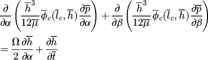 (9)
(9)
2.1 Fluid film thickness
The dimensionless nominal fluid film thickness for two-lobe non-recessed hybrid journal bearing is expressed as [8,9,31]
 (10)
where
(10)
where  and
and  are the journal center co-ordinates,
  and
and  are the coordinates for lobe center.
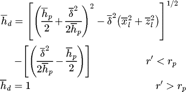
The dimensionless fluid film thickness for micro spherical dimple is expressed as [32,33]
 (11)
where
(11)
where  .
.
The dimensionless fluid film thickness for two-lobe textured non-recessed hybrid journal bearing is expressed as
 (12)
(12)
2.2 Finite element formulation
The fluid flow domain of couple stress lubricant has been discretized using four-noded quadrilateral elements for FEM calculation. The unknown fluid film pressure is considered to be distributed linearly over an element and is defined by [31,32,34]
 (13)
where Nj is the Lagrangian polynomial function and
(13)
where Nj is the Lagrangian polynomial function and  is the number of nodes per element.
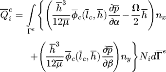
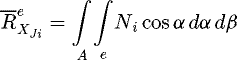
By applying the Galerkin's and FEM techniques, the global system equation is expressed as [8,32,34]
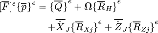 (14)
where
(14)
where
 (15.1)
 (15.2)
 (15.3)
 (15.4)
 (15.5)where nx and ny are direction cosines.
2.3 Restrictor flow equation
The flow rate of couple stress lubricant through the capillary compensating device is expressed by following non-dimensional equation [9,34,35]:
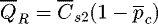 (16)
where
(16)
where  is the non-dimensional parameter for capillary discharge and is obtained by
2.4 Performance characteristics
The two-lobe hybrid journal bearing performance characteristics, i.e., minimum fluid film thickness, frictional torque, external load carrying capacity, lubricant, etc., fall under the category of steady state performance characteristic. Whereas in the category of dynamic performance characteristic, the stiffness and damping coefficients, critical mass and stability threshold speed parameters are included.
2.4.1 Static performance characteristics
The static performance characteristics are simulated after journal centre occupies its equilibrium position  under a given vertical load
  .
.
2.4.1.1 Load carrying capacity
The fluid film pressure obtained from the Reynolds equation is integrated to obtain the fluid film reaction components along X and Z direction as follows [9,30]:
 (17.1)
 (17.2)
The resultant fluid film reaction is obtained as
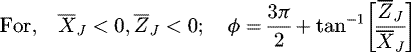
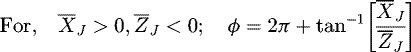
2.4.1.2 Attitude angle
The attitude angle is defined as the angle between the line of action of external load,  and line of center. The line of action of load (i.e., vertical load line) is taken as a reference for computing attitude angle. The attitude angle for different equilibrium positions of journal center are expressed as follows:
 (18.1)
 (18.2)
 (18.3)
 (18.4)
2.4.2 Dynamic performance characteristics
The dynamic performance characteristics are evaluated under the disturbance of the journal centre from its equilibrium position  .
.
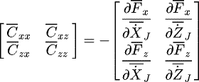
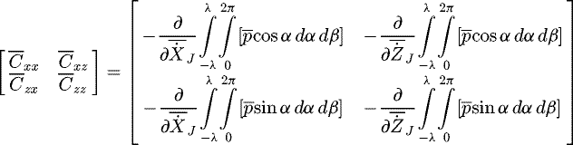
2.4.2.1 Fluid-film stiffness coefficients
The pressure derivative with respect to journal center displacement  gives the expression for fluid film stiffness coefficients and is written by [9,31,34]
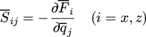 (19.1)
where “i” indicates the force direction and “qj” indicates the direction for journal center displacement
(19.1)
where “i” indicates the force direction and “qj” indicates the direction for journal center displacement  .
.
Stiffness coefficients in matrix form may be expressed as:
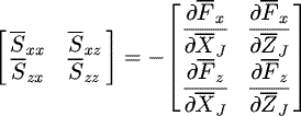 (19.2)
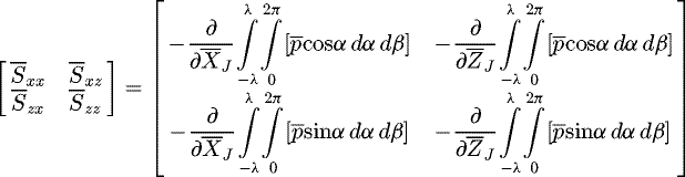 (19.3)
2.4.2.2 Fluid-film damping coefficients
The pressure derivative with respect to journal center velocity  gives the expression for fluid film damping coefficients and is written by [9,31,34]
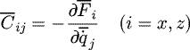 (20.1)
where
(20.1)
where  indicates the journal center velocity
  components.
Damping coefficients in matrix may be expressed as:
 (20.2)
 (20.3)
2.4.2.3 Linearized equations of motion and stability margin
The linearized equation of disturbed motion of the journal about its equilibrium position is framed by equating the inertia force components to the out of balance fluid film force and moment components. In compact form the linearized equation of motion is described as [32,36]
 (21.1)
The linearized system representing the lateral motion of the journal can be reduced in matrix form as [32,36]
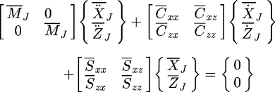 (21.2)
The stability threshold speed margin  is calculated by using the relation given below [32,36]:
 (22)
where
(22)
where  is the resultant fluid-film force
  .
.
 is the non-dimensional critical mass and is expressed as [32,36]
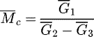 where
where
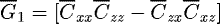


The stability threshold speed margin of the journal bearing system is defined in terms of critical mass  . The system becomes stable, when the journal mass is smaller than the critical mass
  .
.
2.5 Boundary conditions
The following boundary conditions are used to obtain a unique solution from partial differential equation for two-lobe hybrid journal bearing [8,9,31,35]:
-
All nodes at the ends of the bearing boundary were assigned ambient pressure;
-
The nodes located on the boundary of the holes have the same pressure.
-
Restrictor input flow is equal to bearing lubricant flow rate.
-
 is at trailing edge of the positive region for symmetric pressure distribution in the α direction. It is known as Reynolds boundary condition (RBC). This RBC suggested that pressure will smoothly approach zero at the position where cavitation occurs.
3 Solution strategy
The complete details of the solution algorithm to study the combined influence of textured surfaces and behaviour of couple stress lubricant on the performance of tow-lobe hole-entry hybrid journal bearing is illustrated in Figure 4. As the governing Reynolds equation is non-linear in pressure and cannot be solved by using analytical methods, Therefore, a MATLAB program has been developed with the help of FEM formulation as described in the above section. To obtain accurate solution, a uniform fine mesh of 49 × 20 is used in analysis. The solution strategy is implemented in the following steps:
-
1.
The lubricant domain is discretized by using four-node iso-parametric quadrilateral elements.
-
2.
Operating and geometric parameters of the bearing are defined for two-dimensional lubricant grid.
-
3.
Computation of the fluid film thickness for non-textured, textured, circular/non-circular journal bearing using equations (10) and (12) for steady state conditions.
-
4.
Computation of the elements matrices using Gauss points and assemblage into global fluidity matrices.
-
5.
Apply the boundary conditions to global fluidity matrices.
-
6.
The modified Reynolds equation (9) for flow of couple stress lubricant is solved by Gauss–Siedel iterative method to evaluate the nodal fluid film pressure distribution.
-
7.
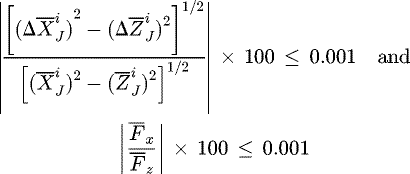
Steps 3–6 are repeated until the following convergence criteria is satisfied for journal center equilibrium position:
-
8.
Once a convergence criterion is satisfied, the performance characteristics of two-lobe hole-entry hybrid journal bearing are computed.
 |
Fig. 4 Solution strategy. |
4 Results and discussion
On the basis of FEM analysis and solution algorithm presented in the previous sections, the combined influence of textured surfaces and couple stress lubricant behaviour on the performance of two-lobe hole-entry hybrid journal bearing is computed. As review of available literature, no published results are available concerning the influence of surface texture with couple stress lubricant on the performance of two-lobe non-recessed hybrid journal bearing in literature. Thus, in order to validate the authenticity of developed numerical model and code, the numerically computed results from the developed program have been compared to the already published data of Lund and Thomsen [37], Mokhiamer et al. [30] and Brizmer and Kligerman [33]. As seen in Table 1, the present simulated results have good agreement with available results of Lund and Thomsen [37] for two-lobe hydrodynamic journal bearing. However, the dimensional load carrying capacity of hydrodynamic journal bearing has been computed for different couple stress parameters at a wide range of eccentricity ratios and validated with published data of Mokhiamer et al. [30]. From Figure 5, the minor deviation has been noticed between present and published results because of the use of different solution technique. Figure 6 shows the comparison of fluid film pressure distribution with the study of Brizmer and Kligerman [33] for textured hydrodynamic journal bearing. The simulated results have reasonably good in trend and values.
In this study, the variation of the static and dynamic bearing characteristics has been computed with external load  and couple stress parameter
  for different types of bearing configurations. The representative operating and geometric parameters have been chosen as reported in Table 2. The numerical values of these parameters have been judiciously chosen from the available literature [8,9,26,29,30,36]. Further, many available studies [8,9,31,36] confirmed that multi-lobe hybrid journal bearings having offset factor greater than one (δ > 1) exhibits better bearing performance characteristics than the bearing having offset factor (δ ≤ 1). Thus, in the present analysis offset factor δ > 1 has been taken into account. Furthermore, the simulated static and dynamic characteristics such as frictional torque, minimum fluid film thickness, fluid film pressure distribution, lubricant flow, attitude angle, fluid film dynamic coefficients and threshold speed are presented in Figures 7–19.
Comparison of bearing characteristic parameters of two-lobe hydrodynamic journal bearing.
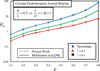 |
Fig. 5 Variation of load carrying capacity |

 |
Fig. 6 Hydrodynamic pressure distribution in short textured journal bearing at mid-plane. |
4.1 Influence on maximum fluid film pressure 
The three-dimensional contour plots of fluid film pressure distribution for circular/non-circular textured/non-textured hole-entry hybrid journal bearing are illustrated in Figures 7–9. Figures 7–9 show the value of maximum fluid film pressure  increase with an increase in the value of couple stress parameter
  for all types of bearing configurations. It can be concluded that the additives with larger chain length molecules, enhances the load carrying capacity of the bearing. Further, it has been observed that the two-lobe journal bearing increases the value of
  with respect to circular journal bearing. The reason is that the two-lobe journal bearing gives a more convergent gap at the bottom of the bearing. From Figures 7–9, it can also be seen that the textured journal bearing reduces the value of
  for Newtonian and couple stress lubricant
  , respectively. Whereas the couple stress lubricant
  lubricated journal bearing enhanced the value of
  for both textured and non-textured journal bearing. For the given value of
  , when the two-lobe (δ = 1.1) non-recessed hole-entry hybrid journal bearing lubricates with couple stress lubricant
  , the value of
  gets enhanced by 21.7% and 15.4% for textured and non-textured journal bearing, respectively, over a circular journal bearing lubricating with Newtonian lubricant.
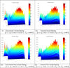 |
Fig. 7 Pressure contour for non-recessed hybrid journal bearing operating with Newtonian lubricant |

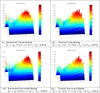 |
Fig. 8 Pressure contour for non-recessed hybrid journal bearing operating with couple stress lubricant |

 |
Fig. 9 Pressure contour for non-recessed hybrid journal bearing operating with couple stress lubricant |

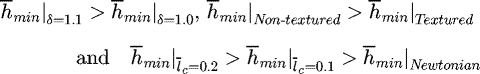
4.2 Influence on minimum fluid film thickness 
Figure 10 shows the influence of couple stress lubricant behaviour on the value of minimum fluid film thickness  of textured/non-textured circular/two-lobe hybrid journal bearing. As seen from Figure 10, it may be noticed that by applying the surface texturing on the bearing surface reduces the minimum fluid film thickness
  . Whereas the minimum fluid film thickness increases for non-circular (δ = 1.1) profile journal bearing. This is due to the fact that the offset factor, δ = 1.1, provides a maximum clearance at the bottom of the bearing. As a result of this, the minimum fluid film thickness increased by adding extra lubricant in the clearance gap. It may also be observed that the value of
  increases with an increase in the value of couple stress parameter
  . Therefore, a bearing with couple stress lubricant can sustain higher value of external load and permits the larger value of
  . At a chosen value of external load,
  , the circular textured journal bearing reduces the value of
  by order of 2.7%, 2.4% and 2.0% for Newtonian, couple stress
  and couple stress
  lubricant, respectively, as compared to the non-textured journal bearing. While the two-lobe (δ = 1.1) textured journal bearing reduces the value of
  in order of 2.6%, 2.4% and 2.1% for Newtonian, couple stress
  and couple stress
  lubricant, respectively, with respect to non-textured tow-lobe journal bearing. In order to maintain the safe limiting value of
  , the following trend may be useful:
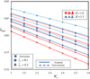 |
Fig. 10 Variation of minimum fluid film thickness |


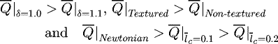
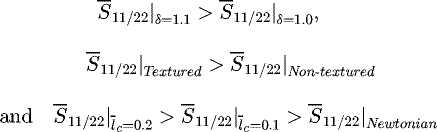
4.3 Influence on lubricant flow 
The variation of dimensionless lubricant flow  with increasing the load carrying capacity
  is depicted in Figure 11. The lubricant flow
  decreases as couple stress parameter
  increases at chosen value of
  . This is because of the larger chain length additives presence in lubricant provides anti-symmetrical stresses and increases the resistance to the flow as well as the wall shear stress. It may be observed that the requirement of lubricant flow rate gets significantly increased for textured journal bearing over a non-textured journal bearing for either of Newtonian
  and couple stress lubricated
  hole-entry hybrid journal bearing configuration. Whereas the two-lobe (δ = 1.1) journal bearing reduces the requirement of lubricant flow rate as compared to circular journal bearing. As seen in Figure 11, the circular textured journal bearing lubricating with Newtonian lubricant gives the higher value of
  whereas provides lowest value of lubricant flow for non-textured two-lobe (δ = 1.1) journal bearing lubricating with couple stress lubricant
  . For the textured two-lobe (δ = 1.1) journal bearing, the maximum increment in the value of
  is order of 36.3%, 39.4% and 47.3% by lubricating with Newtonian, couple stress
  and couple stress
  lubricant, respectively, with respect to corresponding non-textured journal bearing. From the viewpoint of pumping power losses, the bearing designer may make use of the following trend:
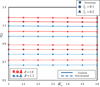 |
Fig. 11 Variation of bearing flow |


4.4 Influence on frictional torque 
The influence of surface texturing along with behaviour of couple stress lubricant on the value of frictional torque  is presented in Figure 12. It can be clearly seen that the non-circular two-lobe (δ = 1.1) journal bearing increases the value of
  for both textured and non-textured journal bearing, consequently increases the power loss than that of circular journal bearing. Therefore, to design an efficient bearing the value of
  should be minimize. Further, the presence of the textured surfaces on the bearing surface reduces the value of
  for both circular and two-lobe hole-entry hybrid journal bearing. It is because of the reason that, textured surfaces acts as a lubricant micro-reservoir and providing the lubricant directly to the contact zone. Further, Figure 12 shows that the value of frictional torque
  decreases with increasing the value of couple stress parameter
  for all types of bearing configurations. For two-lobe (δ = 1.1) textured journal bearing, the percentage reduction in the value of
  is of order of 5.6–6.0%, 5.3–5.9% and 5.1–5.4% for Newtonian, couple stress
  and couple stress
  lubricant has been observed, respectively, as compared to non-textured journal bearing. From the numerically computed results, the bearing designer may use the following definite trend for the value of
  :
:

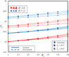 |
Fig. 12 Variation of frictional torque |


4.5 Influence on attitude angle (ϕ)
Figure 13 depicts the variation of attitude angle (ϕ) against load carrying capacity  for textured/no-textured circular/two-lobe hole-entry journal bearings. From Figure 13, it can be observed that the textured hybrid journal bearing operates with lower attitude in comparison to non-textured journal bearing. Further, it may also be noticed that the value of ϕ is significantly reduced with an increase in the values of non-circular offset factor (δ) and couple stress parameter
  . For given value of bearing load
  , the couple stress lubricant
  lubricated textured two-lobe (δ = 1.1) hole-entry bearing reduces the value of ϕ by amount of 21.90% as compared to smooth hole-entry journal bearing lubricating with Newtonian lubricant
  . From the simulated results, following useful trend has been obtained for values of ϕ:

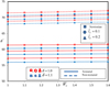 |
Fig. 13 Variation of attitude angle (ϕ) with load carrying capacity |

4.6 Influence on fluid film stiffness coefficients 
The fluid film stiffness is an important bearing characteristic parameter in bearing design. Figures 14 and 15 show the variation of fluid film stiffness coefficients 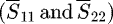 . It may be observed that, the value of stiffness coefficients
  increases with an increase in the value of couple stress parameter
  . The similar pattern has also been observed in the works reported by Guha [29] and Crosby and Chetti [26] for the value of fluid film stiffness coefficients in the case of hydrodynamic and two-lobe journal bearings. The non-circular (δ = 1.1) profile of the bearing enhanced the values of
  and
and  against circular journal bearing. The noticeable observation is that the textured journal bearing gives larger values of
  and
and  as compared to non-textured journal bearing. It may be observed that the influence of couple stress lubricant in the values of fluid film stiffness coefficients
  is significantly more for textured journal bearing against non-textured journal bearing. Further, maximum influence of offset factor (δ) in the values of
  and
and  is observed for textured journal bearing as compared to non-textured journal bearing. As seen from Figure 14, when the two-lobe (δ = 1.1) journal bearing operates with couple stress
  lubricant, the percentage increment in the value of
  is 29.9–31.2% and 3.4–4.0% for textured and non-textured journal bearing, respectively, as compared to corresponding bearing lubricating with Newtonian lubricant. Further, it may be noticed that from Figure 15, the two-lobe (δ = 1.1) textured journal bearing improves the value of
  in order of 5.1–5.8%, 5.3–6.0% and 5.6–6.1% for Newtonian, couple stress
  and couple stress
  lubricant, respectively, against circular textured journal bearing. While the two-lobe (δ = 1.1) non-textured journal bearing enhance the value of
  by an amount of 3.6–3.75%, 3.4–3.6% and 3.2–3.3% for Newtonian, couple stress
  and couple stress
  lubricant, respectively, with respect to circular non-textured journal bearing. From the computed results, the following general pattern has been obtained for the values of
  and
and  :
:
 |
Fig. 14 Variation of fluid film stiffness coefficient |


 |
Fig. 15 Variation of fluid film stiffness coefficient |


4.7 Influence on fluid film damping coefficients 
The effect of couple stress lubricant behaviour on the value of fluid film damping coefficients  is shown in Figures 16 and 17. From Figures 16 and 17, it may be seen that for the textured journal bearing, the values of
  and
and  get reduced as compared to the non-textured journal bearing. The trend for the values of
  and
and  is consistent with observation of already published study [34]. From the vibration point of view, a proper value of fluid film damping coefficients is essential to damp out the shaft vibration under dynamic conditions. Further, the use of couple stress lubricant and non-circular (δ = 1.1) profile bearing partially compensated the reduction in the values of
  and
and  because of the textured surfaces on the bearing surface. As seen in Figure 16, for the given value of external load
  , the textured circular journal bearing reduces the value of
  by amount of 22.86% for Newtonian lubricant as compared to non-textured circular journal bearing. While the two-lobe (δ = 1.1) textured journal bearing lubricates with couple stress
  lubricant, the value of
  is enhanced in order of 6.4% with respect to non-textured circular journal bearing lubricating with Newtonian lubricant. Further, from Figure 17, it may be observed that the two-lobe (δ = 1.1) textured journal bearing improves the value of
  in order of 4.9–5.4%, 5.1–5.6% and 5.6–6.1% for Newtonian, couple stress
  and couple stress
  lubricant, respectively, over a textured circular journal bearing. From the simulated results, following useful trend has been obtained for values of
  and
and  :
:

 |
Fig. 16 Variation of fluid film damping coefficient |


 |
Fig. 17 Variation of fluid film damping coefficient |


4.8 Influence on stability threshold speed 
Figure 18 depicts the variation of stability threshold speed margin  with respect to the load carrying capacity
  . The computed result in Figure 18 indicates that the textured journal bearing provides the greater value of
  for both circular and two-lobe journal bearing. Similarly, the two-lobe (δ = 1.1) journal bearing gives better stability threshold speed margin
  for both textured and non-textured journal bearing than that of circular journal bearing. From Figure 18, it may also be noticed that the influence of couple stress lubricant behaviour and non-circular profile of bearing is significantly more in the value of
  of textured journal bearing than that of non-textured journal bearing. Further, it can be seen that the value of threshold speed margin
  increases with increasing the value of couple stress parameter
  . The value of threshold speed
  depends on the value of bearing rotor dynamic coefficients. As the values of bearing dynamic coefficients get affected due to couple stress parameter
  . Hence, the bearing stability speed margin is bound to change. For the non-recessed hybrid journal bearing, the textured two-lobe (δ = 1.1) bearing lubricating with couple stress lubricant
  gives the highest stability parameter over the other journal bearing configurations. When the two-lobe (δ = 1.1) journal bearing operates with couple stress lubricant
  , the percentage increment in the value of
  is found to be of the order of 12–12.7% and 2.2–2.5% for textured and non-textured journal bearing with respect to corresponding bearing operating with Newtonian lubricant. To design an efficient stable journal bearing, the following trend may follow:
  ,
,  and
and  .
.
Furthermore, Figure 19 shows the linear journal motion trajectories for circular/non-circular textured/non-textured journal bearings. From Figure 19, it may be revealed that the textured bearing surfaces traces a small orbit for come back from disturbed journal centre position to equilibrium journal centre position in comparison to non-textured journal bearing. Smaller whirl orbit size indicates that journal centre fluctuates around its equilibrium position with lower amplitude of vibration. It has been also noticed that the use of couple stress lubricant and non-circular profile on bearing gives small locus of journal centre and settles down quickly to equilibrium position of journal centre. Hence, based on simulated trajectories, we can say that the couple stress lubricant lubricated textured two-lobe (δ = 1.1) textured journal bearing is highly beneficial from stability point of view.
The comparative performance of two-lobe textured hybrid journal bearing against non-textured circular journal bearing considering the influence of couple stress lubricant is presented in Table 3. It has been noticed that the two-lobe textured journal bearing lubricated with couple stress lubricant  provides improved performance with respect to circular non-textured journal bearing. However, at a chosen value of external load
  , the two-lobe textured journal bearing operating with couple stress lubricant
  gives enhancement in the value of stability threshold speed margin
  with 38.14% as compared to base journal bearing as seen in Table 3.
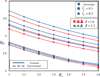 |
Fig. 18 Variation of stability threshold margin |


 |
Fig. 19 Trajectories for journal centre motion of hole-entry hybrid journal bearing. |
Percentage change in the dimensional value of selected performance characteristic parameters of two-lobe hole-entry hybrid journal bearing.
5 Conclusion
In the present study, the performance of two-lobe hole-entry hybrid journal bearing has been analyzed by considering the combined effects of surface texturing on bearing surface and behaviour of couple stress lubricant. On the basis of computed results in present study, the following conclusions are summarized:
-
The use of couple stress lubricant, two-lobe (δ = 1.1) bearing and textured surface on hole-entry hybrid journal bearing gives higher values of minimum fluid film thickness
 over the Newtonian lubricant lubricated circular non-textured journal bearing. It means the couple stress lubricant lubricated textured two-lobe journal bearing can sustain higher value of external load than that of non-textured circular journal bearing lubricating with Newtonian Lubricant.
 -
For a hole-entry hybrid journal bearing configuration, the presence of surface texturing on the bearing surface increases the lubricant flow rate
 . However, the use of couple stress lubricant and two-lobe (δ = 1.1) profile bearing reduces the requirement of lubricant flow
  . Hence, from the viewpoint of pumping power losses, the couple stress lubricant lubricated two-lobe (δ = 1.1) textured hole-entry journal bearing is beneficial than the Newtonian lubricant lubricated circular non-textured journal bearing.
 -
The two-lobe (δ = 1.1) profile of the hole-entry hybrid journal bearing results in an increase of the value of frictional torque
 . Further, the presence of surface texturing and couple stress lubricant reduces the value of
  significantly for all types of bearing configurations. Therefore, from the viewpoint of frictional power losses (minimization of bearing temperature), the couple stress lubricant lubricated two-lobe (δ = 1.1) textured hole-entry journal bearing is beneficial than the Newtonian lubricant lubricated circular non-textured journal bearing.
 -
For a circular/two-lobe hole-entry hybrid journal bearing, the influence of couple stress lubricant is significantly high on the values of fluid film stiffness coefficients (
 ,
,  ) and stability threshold margin (
 ) for textured journal bearing in comparison to non-textured journal bearing. Further, it may also be seen that the combination of two-lobe (δ = 1.1) profile, couple stress lubricant and textured surface provides the small radius of whirl orbit to settle down the journal centre to equilibrium position after some disturbances owing to unbalanced fluid film forces. Hence, it may be point out that the couple stress lubricant lubricated two-lobe (δ = 1.1) textured journal bearing is highly beneficial from stability point of view.
 -
The textured hole-entry hybrid journal bearing system reduces the values of fluid film, damping coefficients (
 and
and  ). However, the use of couple stress lubricant in a two-lobe (δ = 1.1) journal bearing gives improvement in the values of
  and
and  . Hence, to significantly damp out the unwanted oscillations of journal bearing, the combination of textured surface, non-circular profile and couple stress lubricant is beneficial than the Newtonian lubricant lubricated circular non-textured journal bearing.
Conflicts of interest
The authors declare that they have no conflicts of interest in relation to this article.
Nomenclature
ab: Bearing land width, mm
c: Radial clearance, mm
c1: Minor clearance when journal and bearing center are coincident, mm
c2: Conventional clearance, mm
Cij: Damping coefficients (i, j = 1, 2), N ⋅ s ⋅ mm−1
Cs2: Restrictor design parameter
D: Journal diameter, mm
e: Journal eccentricity, mm
F:
Fluid film reaction  , N
, N
Fx, Fz:
X and Z components of fluid film reactions  , N
, N
Fo:
Fluid film reaction  , N
, N
g: Gravitational acceleration, m·s−2
h: Local fluid-film thickness, mm
hr = c: Reference fluid film thickness, mm
hp: Dimple depth, mm
hmin: Minimum fluid film thickness, mm
K: Number of holes per row
L: Bearing length, mm
lc: Characteristics length of the additives, lc = (η/μ)1/2
lcp: Length of capillary, mm
MJ: Journal mass, kg
Mc: Critical mass of journal, kg
N: Number of rows of holes
OJ: Journal center
Ob: Bearing center
OL: Lobe center
p: Pressure, MPa
ps: Supply pressure, MPa
pc: Pressure at holes, MPa
Q: Bearing flow, mm3·s−1
RJ: Radius of journal, mm
rcp: Radius of capillary, mm
Rb: Radius of bearing, mm
rp: Base radius of dimple, mm
Sij: Stiffness coefficients (i, j = 1, 2), N·mm−1
So: Sommerfeld number
t: Time, s
u, v: Circumferential and axial directional velocities
Wo: External load, N
 :
Lobe center co-ordinates
:
Lobe center co-ordinates
xl, zl: Local Cartesian coordinates of dimple
X, Y, Z: Cartesian coordinates
XJ, ZJ: Journal center coordinates, mm
Greek symbols
ρ: Lubricant density, kg·mm−3
μ: Lubricant viscosity, N·s·m−2
ωJ: Journal rotational speed, rad·s−1
ωI:
 , rad·s−1
ϕ: Altitude angle, rad
ωth: Threshold speed, rad·s−1
λ = L/D: Aspect ratio
μr: Reference viscosity of lubricant, N·s·m−2
η: Material constant responsible for the couple stress property
Non-dimensional parameters
 :
:
 , land width ratio
 :
:
 :
:
 :
:
 :
:

 :
(hp)/hr
:
(hp)/hr
 :
:

 :
(p, pc, pmax)/ps
:
(p, pc, pmax)/ps
 :
Q(μ/c3ps)
:
Q(μ/c3ps)
 :
rp/ro
:
rp/ro
 :
:
 :
:

 :
(XJ, ZJ)/c
:
(XJ, ZJ)/c
 :
:

 :
:
ϵ: e/c, eccentricity ratio
β∗: p/ps, concentric design pressure ratio (∂ h/∂ t = 0)
δ:
 , offset factor
 :
lc/c, couple stress parameter
:
lc/c, couple stress parameter
α, β: (X, Y)/RJ, circumferential and axial coordinates
 :
z/hL, coordinates across fluid-film thickness
:
z/hL, coordinates across fluid-film thickness
 :
Dimensionless dimple radius
:
Dimensionless dimple radius
 :
ωth/ωI
:
ωth/ωI
 :
:

Ω:
 , speed parameter
 :
Velocity components of journal center
:
Velocity components of journal center
Matrices
 :
assembled fluidity matrix
:
assembled fluidity matrix
 :
nodal pressure column vector
:
nodal pressure column vector
 :
nodal flow column vector
:
nodal flow column vector
 :
column vectors due to hydrodynamic terms
:
column vectors due to hydrodynamic terms
 :
global RHS vector due to squeeze velocities
:
global RHS vector due to squeeze velocities
Subscripts and superscripts
J: journal
b: bearing
s: supply
R: restrictor
max: maximum
min: minimum
c: capillary
e: eth element
“·”: first derivative w.r.t. time
—: corresponding dimensionless parameter
r: reference value
“··”: second derivative w.r.t. time
References
- A. Laratta, Oil whirl of rotors. Part I: vertical shafts, Meccanica 4 (1969) 336–348 [CrossRef] [Google Scholar]
- O. Pinkus, M. Lynn, Analysis of elliptical bearings, Trans. ASME 78 (1956) 965–976 [Google Scholar]
- O. Pinkus, Power losses in elliptical and 3-lobe bearings, Trans. ASME 78 (1956) 899–904 [Google Scholar]
- P.K. Goenka, J. Booker, Effect of surface ellipticity on dynamically loaded cylindrical bearings, J. Tribol. 105 (1983) 1–9 [Google Scholar]
- M. Malik, A comparative study of some two-lobed journal bearing configurations, ASLE Trans. 26 (1983) 118–124 [CrossRef] [Google Scholar]
- W. Crosby, A thermohydrodynamic solution of the two-lobe bearing considering reverse flow at the leading and trailing edges, Wear 143 (1991) 159–173 [CrossRef] [Google Scholar]
- G.J. Kostrzewsky, D.V. Taylor, R.D. Flack, L.E. Barrett, Theoretical and experimental dynamic characteristics of a highly preloaded three-lobe journal bearing, Tribol. Trans. 41 (1998) 392–398 [CrossRef] [Google Scholar]
- J. Sharana Basavaraja, S. Sharma, S. Jain, A study of misaligned roughened two-lobe hole-entry hybrid journal bearing, Ind. Lubr. Tribol. 61 (2009) 220–227 [CrossRef] [Google Scholar]
- S.C. Sharma, P.B. Kushare, Two lobe non-recessed roughened hybrid journal bearing – a comparative study, Tribol. Int. 83 (2015) 51–68 [CrossRef] [Google Scholar]
- J. Greenwood, J. Wu, Surface roughness and contact: an apology, Meccanica 36 (2001) 617–630 [CrossRef] [Google Scholar]
- N. Tala-Ighil, M. Fillon, Surface texturing effect comparative analysis in the hydrodynamic journal bearings, Mech. Ind. 16 (2015) 302 [CrossRef] [Google Scholar]
- A. Charitopoulos, D. Fouflias, C.I. Papadopoulos, L. Kaiktsis, M. Fillon, Thermohydrodynamic analysis of a textured sector-pad thrust bearing: effects on mechanical deformations, Mech. Ind. 15 (2014) 403–411 [CrossRef] [Google Scholar]
- I. Etsion, G. Halperin, V. Brizmer, Y. Kligerman, Experimental investigation of laser surface textured parallel thrust bearings, Tribol. Lett. 17 (2004) 295–300 [CrossRef] [Google Scholar]
- R.B. Siripuram, L.S. Stephens, Effect of deterministic asperity geometry on hydrodynamic lubrication, J. Tribol. 126 (2004) 527–534 [CrossRef] [Google Scholar]
- S. Cupillard, M.J. Cervantes, S. Glavatskih, Pressure buildup mechanism in a textured inlet of a hydrodynamic contact, J. Tribol. 130 (2008) 021701 [CrossRef] [Google Scholar]
- S. Cupillard, S. Glavatskih, M. Cervantes, Computational fluid dynamics analysis of a journal bearing with surface texturing, Proc. Inst. Mech. Eng. J.: J. Eng. Tribol. 222 (2008) 97–107 [Google Scholar]
- S. Kango, D. Singh, R. Sharma, Numerical investigation on the influence of surface texture on the performance of hydrodynamic journal bearing, Meccanica 47 (2012) 469–482 [CrossRef] [Google Scholar]
- I. Syed, M. Sarangi, Hydrodynamic lubrication with deterministic micro textures considering fluid inertia effect, Tribol. Int. 69 (2014) 30–38 [CrossRef] [Google Scholar]
- B. Bou-Said, H. Boucherit, M. Lahmar, On the influence of particle concentration in a lubricant and its rheological properties on the bearing behavior, Mech. Ind. 13 (2012) 111–121 [CrossRef] [Google Scholar]
- V.K. Stokes, Couple stresses in fluids, Phys. Fluids (1958–1988) 9 (1966) 1709–1715 [CrossRef] [Google Scholar]
- V.K. Stokes, Effects of couple stresses in fluids on the creeping flow past a sphere, Phys. Fluids (1958–1988) 14 (1971) 1580–1582 [CrossRef] [Google Scholar]
- G. Ramanaiah, P. Sarkar, Slider bearings lubricated by fluids with couple stress, Wear 52 (1972) 27–36 [CrossRef] [Google Scholar]
- J.R. Lin, Effects of couple stresses on the lubrication of finite journal bearings, Wear 206 (1997) 171–178 [CrossRef] [Google Scholar]
- J.R. Lin, Linear stability analysis of rotor-bearing system: couple stress fluid model, Comput. Struct. 79 (2001) 801–809 [CrossRef] [Google Scholar]
- Y.Y. Ma, W.H. Wang, X.H. Cheng, A study of dynamically loaded journal bearings lubricated with non-Newtonian couple stress fluids, Tribol. Lett. 17 (2004) 69–74 [CrossRef] [Google Scholar]
- W. Crosby, B. Chetti, The static and dynamic characteristics of a two-lobe journal bearing lubricated with couple-stress fluid, Tribol. Trans. 52 (2009) 262–268 [CrossRef] [Google Scholar]
- X.L. Wang, K.Q. Zhu, S.Z. Wen, On the performance of dynamically loaded journal bearings lubricated with couple stress fluids, Tribol. Int. 35 (2002) 185–191 [CrossRef] [Google Scholar]
- C. Singh, Lubrication theory for couple stress fluids and its application to short bearings, Wear 80 (1982) 281–290 [CrossRef] [Google Scholar]
- S. Guha, A theoretical analysis of dynamic characteristics of finite hydrodynamic journal bearings lubricated with coupled stress fluids, Proc. Inst. Mech. Eng. J: J. Eng. Tribol. 218 (2004) 125–133 [CrossRef] [Google Scholar]
- U. Mokhiamer, W. Crosby, H. El-Gamal, A study of a journal bearing lubricated by fluids with couple stress considering the elasticity of the liner, Wear 224 (1999) 194–201 [CrossRef] [Google Scholar]
- P.B. Kushare, S.C. Sharma, Influence of wear on the performance of 2-lobe slot entry hybrid journal bearings, Mech. Ind. 16 (2015) 502 [CrossRef] [Google Scholar]
- C.B. Khatri, S.C. Sharma, Influence of textured surface on the performance of non-recessed hybrid journal bearing operating with non-Newtonian lubricant, Tribol. Int. 95 (2016) 221–235 [CrossRef] [Google Scholar]
- V. Brizmer, Y. Kligerman, A laser surface textured journal bearing, J. Tribol. 134 (2012) 031702 [CrossRef] [Google Scholar]
- S.C. Sharma, S.K. Yadav, Performance analysis of a fully textured hybrid circular thrust pad bearing system operating with non-Newtonian lubricant, Tribol. Int. 77 (2014) 50–64 [CrossRef] [Google Scholar]
- W.B. Rowe, S.X. Xu, F.S. Chong, W. Weston, Hybrid journal bearings with particular reference to hole-entry configurations, Tribol. Int. 15 (1982) 339–348 [CrossRef] [Google Scholar]
- P.B. Kushare, S.C. Sharma, Nonlinear transient stability study of two lobe symmetric hole entry worn hybrid journal bearing operating with non-Newtonian lubricant, Tribol. Int. 69 (2014) 84–101 [CrossRef] [Google Scholar]
- J. Lund, K. Thomsen, A calculation method and data for the dynamic coefficients of oil-lubricated journal bearings, in: Topics in fluid film bearing and rotor bearing system design and optimization, Dyrobes, 1978, p. 1000118 [Google Scholar]
Cite this article as: C.B. Khatri, S.C. Sharma, Performance of two-lobe hole-entry hybrid journal bearing system under the combined influence of textured surface and couple stress lubricant, Mechanics & Industry 18, 603 (2017)
All Tables
Comparison of bearing characteristic parameters of two-lobe hydrodynamic journal bearing.
Percentage change in the dimensional value of selected performance characteristic parameters of two-lobe hole-entry hybrid journal bearing.
All Figures
|
Fig. 1 Two-lobe hole-entry hybrid journal bearing system. |
| In the text | |
|
Fig. 2 Non-textured hole-entry journal bearing configuration. |
| In the text | |
|
Fig. 3 Textured hole-entry journal bearing configuration. |
| In the text | |
|
Fig. 4 Solution strategy. |
| In the text | |
|
Fig. 5 Variation of load carrying capacity |
| In the text | |
|
Fig. 6 Hydrodynamic pressure distribution in short textured journal bearing at mid-plane. |
| In the text | |
|
Fig. 7 Pressure contour for non-recessed hybrid journal bearing operating with Newtonian lubricant |
| In the text | |
|
Fig. 8 Pressure contour for non-recessed hybrid journal bearing operating with couple stress lubricant |
| In the text | |
|
Fig. 9 Pressure contour for non-recessed hybrid journal bearing operating with couple stress lubricant |
| In the text | |
|
Fig. 10 Variation of minimum fluid film thickness |
| In the text | |
|
Fig. 11 Variation of bearing flow |
| In the text | |
|
Fig. 12 Variation of frictional torque |
| In the text | |
|
Fig. 13 Variation of attitude angle (ϕ) with load carrying capacity |
| In the text | |
|
Fig. 14 Variation of fluid film stiffness coefficient |
| In the text | |
|
Fig. 15 Variation of fluid film stiffness coefficient |
| In the text | |
|
Fig. 16 Variation of fluid film damping coefficient |
| In the text | |
|
Fig. 17 Variation of fluid film damping coefficient |
| In the text | |
|
Fig. 18 Variation of stability threshold margin |
| In the text | |
|
Fig. 19 Trajectories for journal centre motion of hole-entry hybrid journal bearing. |
| In the text | |
Current usage metrics show cumulative count of Article Views (full-text article views including HTML views, PDF and ePub downloads, according to the available data) and Abstracts Views on Vision4Press platform.
Data correspond to usage on the plateform after 2015. The current usage metrics is available 48-96 hours after online publication and is updated daily on week days.
Initial download of the metrics may take a while.