| Issue |
Mechanics & Industry
Volume 19, Number 2, 2018
|
|
|---|---|---|
| Article Number | 203 | |
| Number of page(s) | 15 | |
| DOI | https://doi.org/10.1051/meca/2018015 | |
| Published online | 03 September 2018 | |
Regular Article
Numerical analysis of the effects of compression ring wear and cylinder liner deformation on the thermal mixed lubrication performance of ring-liner system
1
School of Mechanical and Precision Instrument Engineering, Xi'an University of Technology,
Xi'an
710048, PR China
2
State Key Laboratory of Digital Manufacturing Equipment and Technology, Huazhong University of Science and Technology,
Wuhan
430074, PR China
3
School of Printing, Packaging Engineering and Digital Media Technology, Xi'an University of Technology,
Xi'an
710048, PR China
4
School of Mechanical and Electrical Engineering, Lanzhou University of Technology,
Lanzhou
730050, PR China
5
College of Engineering, Michigan State University,
East Lansing,
MI
48824, USA
* e-mail: This email address is being protected from spambots. You need JavaScript enabled to view it.
Received:
28
August
2017
Accepted:
6
February
2018
Abstract
The lubrication performance of roughness compression ring-cylinder liner system (CRCL) with axial-asymmetric new/worn compression ring and out-of-round cylinder liner is studied in this paper. By considering the oil film thermal effect, cavitation phenomenon, and surface roughness, the energy equations, mass conservation Jacoboson-Floberg-Olsson (JFO) cavitation algorithm, generalized average Reynolds equation, and Greenwood-Tripp asperity contact model are employed to investigate the frictional behaviors of CRCL. The oil film thickness, friction forces, wear, and power loss of CRCL are investigated at various wear stages of compression ring. The effects of the magnitude of cylinder liner deformation on the frictional characteristics of CRCL are also analyzed with consideration of compression ring conformability. Numerical results show that the deformation of cylinder liner and the wear of compression ring have a significant influence on the lubrication performance. It also suggests that the oil film thermal effect should be considered in the numerical analysis to provide an accurate prediction on the frictional behaviors of CRCL.
Key words: Frictional performance / compression ring-cylinder liner system / thermal analysis / out-of-round cylinder liner / JFO cavitation algorithm
© AFM, EDP Sciences 2018
1 Introduction
With the development of modern internal combustion engines (ICEs), more and more attention has been paid to the reductions of friction loss and fuel energy consumption because they affect emissions and fuel efficiency greatly [1–3]. In ICEs, about 20% of total friction loss and 5% of fuel energy consumption are caused by the friction of piston ring-cylinder liner system (PRCL) [4,5]. Therefore, reducing the friction of PRCL is crucial for ICEs to improve the emissions and fuel efficiency [6,7]. In order to minimize the friction of PRCL, the frictional characteristics of PRCL have been extensively studied in recent years.
For PRCL in working conditions, various regimes of lubrication (hydrodynamic, mixed, and boundary) will be encountered in an engine cycle because of the rapidly changing velocity, highly fluctuating thermal and structural loads [8]. Generally, the PRCL is under hydrodynamic regime in the majority of the engine cycle, and under mixed or boundary regimes at piston dead centers [9]. In consideration of the dominant lubrication regime of hydrodynamic in the engine cycle of PRCL, Jeng et al. [10] conducted a one-dimensional lubrication analysis for PRCL by solving Reynolds equation. The minimum oil film thickness between the piston ring and the cylinder liner was investigated for various engine speeds, piston ring tensions, and piston ring face profiles. Livanos et al. [11] investigated the effects of engine speed and load on the friction of compression ring using a piston assembly friction model. Higher minimum oil film thickness and lower friction loss were observed for the piston ring with smaller load. Taylor et al. [12] studied the oil film thickness and pressure of PRCL using a one-dimensional lubrication model with and without squeeze film effects. The squeeze film effects were observed to have a great impact on the oil film thickness at reversal positions. Usman et al. [13] investigated the oil film thickness, friction force, and power loss of PRCL for the oil with different viscosity grades. The low viscous oils showed better tribological performance under engine start-up conditions.
By considering the mixed or boundary lubrication regimes of PRCL at piston dead centers, Hamatake et al. [14] studied the frictional characteristics of a piston ring pack for different monograde and multigrade oils. Ali et al. [15] investigated the effects of the piston ring dynamic behavior and oil viscosity on the frictional characteristics of PRCL. Their results showed that the low viscosity oil has small friction loss and oil consumption. More recently, Obert et al. [16] investigated the influence of oil supply and liner temperature on the friction coefficient of PRCL. Rahmani et al. [17] studied the power loss and emissions of compression ring at various liner temperatures. Their results demonstrated that the control of liner temperature can help to reduce the power loss and emissions, and the friction coefficient was not influenced by the oil supply rate and liner temperature. By using the measured liner surface topographies, Profito et al. [18] evaluated the shear stress and pressure of oil control ring experimentally. Significant differences in pressures and shear stresses were observed for new and worn liner surfaces. Zhang et al. [19] investigated the friction and pressure in PRCL for various piston ring profiles, and a sequential quadratic programming algorithm was used to obtain the best profile of piston ring for minimum friction and maximum load-carrying capacity. In these works, an ideal circular cylinder liner and an axial symmetrical piston ring were considered in the performance analysis of PRCL.
In practice, the piston ring face profile is usually asymmetrical in axial direction because of the different tribological and dynamic behaviors in upstrokes and downstrokes [20,21]. And similarly, the cylinder liner is usually out-of-round because of the thermal loads, high combustion pressures, manufacturing errors, and load difference between thrust and anti-thrust sides [22,23]. Considering the asymmetrical face profile of piston ring in the axial direction, Morris et al. [24] and Chong et al. [25] studied the frictional performance of PRCL, the minimum oil film thickness and friction between the piston ring and the cylinder liner were predicted for new and worn piston rings. Their results showed that the worn piston ring increased the oil film thickness and decreased the frictional loss. In these works, the cylinder liner is also assumed to be ideal circular. Considering the out-of-round cylinder liner, Usman et al. [26,27] investigated the minimum oil film thickness and power loss of PRCL with various out-of-round liner profiles. Their results demonstrated that the out-of-round liner profile has a great influence on the frictional performance of PRCL. In the above works, the isothermal condition was considered in the tribological performance analysis of PRCL. Under the usual fired engine condition, the generated heat in PRCL will changes the oil viscosity and density, and then changes the frictional characteristics [28,29]. In order to provide more detailed information about the frictional behavior of PRCL, the thermal analysis should be taken into consideration.
In this paper, the lubrication performance of a roughness compression ring-cylinder liner system (CRCL) with axial-asymmetric new/worn compression ring and out-of-round cylinder liner is investigated. By considering the oil film thermal effect, cavitation phenomenon, and surface roughness, a thermal-mixed lubrication model is presented to evaluate the minimum oil film thickness, friction force, power loss, and wear in CRCL based on the generalized average Reynolds equation, energy equations, JFO cavitation algorithm, and Greenwood-Tripp asperity contact model. On this basis, the friction characteristics of CRCL are analyzed at various wear stages of compression ring. The effects of cylinder liner out-of-roundness on the lubrication performance of CRCL are also analyzed with consideration of compression ring conformability.
2 Theoretical model
2.1 Geometrical model and expression of oil film thickness
Figure 1 shows the schematic diagram of CRCL. The compression ring moves up and down in the cylinder liner to provide a seal between the combustion chamber and the crankcase. The time-varying velocity of compression ring can be expressed as [17]:
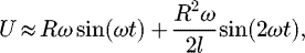 (1)
where R is the radius of crankshaft, ω is the angular velocity of crankshaft, l is the length of connecting rod.
(1)
where R is the radius of crankshaft, ω is the angular velocity of crankshaft, l is the length of connecting rod.
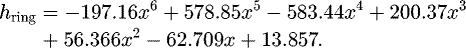
In ICEs, the face profile of compression ring is usually asymmetrical in the axial direction [20,21], and the wear of compression ring is inevitable because of serious solid-solid contact caused by the high cylinder pressure and temperature [30,31]. In this study, in order to investigate the influence of compression ring wear on the lubrication performance of CRCL, the asymmetrical compression rings in various wear degrees or after various service time (i.e., the un-wear compression ring (new compression ring), run-in compression ring, and embedded compression ring) are considered. In details, the run-in compression ring represents the ring after its initial run-in wear (after 10 000 km service), and the embedded compression ring represents the ring at the end of its useful life (after 150 000 km service). Figure 2a shows the axial face profiles of the new compression ring, run-in compression ring, and embedded compression ring. In Figure 2a, hring is the additional gap between the compression ring and cylinder liner caused by the axial face profiles of compression ring. Because of different wear degrees or service time, the axial face profiles of run-in compression ring, embedded compression ring and new compression ring are quite different. The different axial face profiles of run-in compression ring, embedded compression ring and new compression ring will result in different values of hring, and subsequently result in different oil film thicknesses between the compression ring and cylinder liner, and lubrication performance. By measuring the face profiles with an optical Talysurf profilometer, the additional gaps between the compression ring and cylinder liner caused by the axial face profiles of run-in compression ring, embedded compression ring and new compression ring can be fitted by the polynomial equations [21]. The additional gap between the compression ring and cylinder liner caused by the axial face profile of new compression ring hring can be written as [21]:
 (2)
(2)
Likewise, the additional gap between the compression ring and cylinder liner caused by the axial face profile of run-in compression ring hring can be written as [21]:
 (3)
(3)
The additional gap between the compression ring and cylinder liner caused by the axial face profile of embedded compression ring hring can be written as [21]:
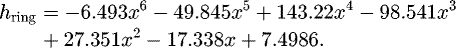 (4)
It should be noted that the units of x and hring are millimetre and micrometre, respectively.
(4)
It should be noted that the units of x and hring are millimetre and micrometre, respectively.
Moreover, the cylinder liner is usually deformed because of the thermal loads, high combustion pressures, manufacturing errors, and load difference between thrust and anti-thrust sides [22,23]. The cylinder liner deformation also changes the profile of cylinder liner, and consequently causes an additional gap between the compression ring and cylinder liner. Considering the conformability of compression ring, the additional gap between the compression ring and the cylinder liner caused by the cylinder liner deformation hliner can be predicted as [27]:
 (5)
with
(5)
with
 (6)
(6)
 (7)
(7)
where ΔR is the radius variation of cylinder liner caused by the liner deformation, ΔRmin is the minimum variation in cylinder liner radius, Un is the elastic deformation of compression ring caused by the conformability of compression ring, a is the radial thickness of compression ring, r is the nominal radius of cylinder liner, E is the Young's modulus of compression ring, Δc is the maximum deformation of cylinder liner, ϕ is the circumferential position, ϕn is the circumferential position of the maximum liner deformation, Ft is the tension force of compression ring, Fbp is the backpressure force. n is the order of cylinder liner deformation. According to the works of Usman et al. [27], a typical value of n = 4 is used in this work. Figure 2b shows the schematic diagram of out-of-round cylinder liner with 4th-order deformation and the conformability of compression ring.
For CRCL, both of the wear of compression ring and cylinder liner deformation change the profiles of compression ring and cylinder liner, and subsequently result in different gaps between the compression ring and cylinder liner. In the lubrication analysis of CRCL, different gaps between the compression ring and cylinder liner means different oil film thickness in CRCL, which consequently result in different hydrodynamic pressure distribution and frictional behaviors. The oil film thickness for CRCL with deformed cylinder liner and new/worn compression ring h can be expressed as:
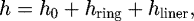 (8)where h0 is the minimum oil film thickness between the compression ring and cylinder liner.
It should be noted that the thermal effect will results in different temperature distribution in the compression ring [27], and subsequently causes a thermal expansion/distortion. The thermal expansion/distortion reduces the ring-end gap, alters the oil film thickness, and subsequently results in an additional tension pressure acting on the compression ring. Usman et al. [27] discussed the influence of thermal expansion/distortion of compression ring on the performance of CRCL. They pointed out that the expansion/distortion of compression ring usually varies within several microns, which will results in negligible changes in the ring-end gap, tension pressure, oil film thickness, and frictional performance of CRCL. Therefore, based on the discussion of Usman et al. [27], the compression ring expansion/distortion caused by thermal effect is not considered in this study. Similar neglect of the effect of thermal expansion/distortion of compression ring can be also found in the works [24,28].
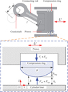 |
Fig. 1 Schematic diagram of CRCL. |
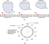 |
Fig. 2 (a) Face profiles of new compression ring, run-in compression ring, and embedded compression ring; (b) schematic diagram of deformed cylinder liner and compression ring conformability [27]. |
2.2 Governing equation
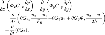
In this study, the hydrodynamic pressure of oil film in CRCL considering the variable density and viscosity in the x, y, and z directions can be described by the generalized Reynolds equation. Moreover, the surface roughness affects greatly the lubrication performance of CRCL, especially under the mixed/boundary lubrication regime [9]. In order to simulate the effects of surface roughness on the lubrication performance, two different methods (i.e., the direct/deterministic method and the indirect/stochastic method) are usually adopted [32,33]. In this study, an indirect/stochastic method proposed by Patir and Cheng [34] is employed to simulate the effects of surface roughness on the lubrication performance of CRCL because of its low cost in computation time and easy realization [33]. The generalized Reynolds equation with consideration of Patir and Cheng's approach and mass conservation JFO cavitation algorithm [35,36] is given as follows [37]:
 (9)
with
(9)
with


where x and y are the coordinates in the axial and circumferential directions, p is the hydrodynamic pressure of oil film, ρ is the oil density, η is the oil viscosity, t is the time. u1 = 0 and u2 = U are the velocities of cylinder liner and compression ring. Φx and Φy are the pressure flow factors, Φs is the shear flow factor, and they are defined by Patir and Cheng [34,38]. It should be noticed that the Patir and Cheng's approach can be applied to arbitrary surface roughness structures with Gaussian distributed asperity heights [34]. For CRCL in actuality, the cylinder liner surface is usually cross-hatched and honed, and the asperity height of roughness liner surface in running-in condition usually obeys an approximate Gaussian distribution [39]. However, according to the work of Morris et al. [39], the Patir and Cheng's approach is reasonable and acceptable in the simulation of roughness CRCL when the asperity height of roughness liner surface is assumed to be Gaussian distributed. This indicated that the Patir and Cheng's approach can be applied to simulate the roughness CRCL, even though the asperity height of roughness liner surface is not strictly Gaussian distributed [39]. More accurate simulation on the roughness surfaces can be also conducted from the measured topography [40].
Based on the JFO theory, the saturation of the fluid θ is given as follows [37]:
 (10)
where pc is the cavitation pressure.
(10)
where pc is the cavitation pressure.
The pressure boundary conditions are necessary for the solving of oil film pressure. In the current study, a fully flooded lubrication condition is assumed, and the pressure boundary conditions are given as follows [21]:
 (11)
where pt is the cylinder pressure, pl is the gas pressure under the compression ring.
(11)
where pt is the cylinder pressure, pl is the gas pressure under the compression ring.
2.3 Asperity contact model
The lubrication regime of CRCL is usually mixed at piston dead centers. In this case, the asperity contact between the compression ring and the cylinder liner is inevitable. The tension force Ft and the backpressure force Fbp are balanced by the oil film force Foil and the asperity contact force Fasp, as shown in Figure 1. In order to investigate the asperity contact behaviors in CRCL, the well-known Greenwood-Tripp asperity contact model is employed to predict the asperity contact force Fasp and the asperity contact area Ac [21,24].
 (12)
(12)
 (13)
(13)
where E' is the equivalent elastic modulus of CRCL, σ is the comprehensive surface roughness of CRCL, κ is the density of asperity, β is the curvature radius of asperity, λ = h/σ is the oil film thickness ratio, A is the apparent asperity contact area. F2.5(λ) and F2(λ) are the statistic functions of roughness surface with Gaussian distributed asperities, they can be expressed as [41]:
 (14)
(14)
 (15)
(15)
2.4 Rheological relationship
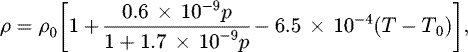
The oil viscosity and density affect greatly the frictional performance. Generally, the oil viscosity and density are determined by the oil film temperature and pressure. The viscosity-pressure-temperature relationship and density-pressure-temperature relationship of oil film can be described by [42]:
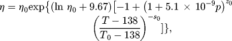 (16)
(16)
 (17)
with
(17)
with
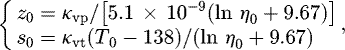 (18)where κvp is the viscosity-pressure coefficient of oil film, κvt is the viscosity-temperature coefficient of oil film, T0 is the oil film temperature under atmospheric pressure, η0 and ρ0 are the oil film viscosity and density under atmospheric pressure when oil film temperature equals to T0.
2.5 Thermal analysis
During the running of CRCL, the friction heat causes an increase of oil film temperature, and then changes the viscosity and density. In this study, the three-dimensional energy equation is employed to calculate the oil film temperature distribution [42].
 (19)
(19)
Moreover, in order to calculate the temperature distribution of oil film accurately, the heat transfer equations for the solids (i.e., compression ring and cylinder liner) should be solved simultaneously because some heat is conducted to the solids. Because the solids densities and velocities in the x direction are constants, and the solids velocities in the y and z direction are zero, the heat transfer equations for the compression ring and cylinder liner can be rewritten as [42]:
 (20)
(20)
 (21)
(21)
where cp and kp are the specific heat capacity and thermal conductivity of oil film, cr and kr are the specific heat capacity and thermal conductivity of compression ring, cl and kl are the specific heat capacity and thermal conductivity of cylinder liner, ρr and ρl are the densities of compression ring and cylinder liner. u and v are the velocities of oil film in the x and y directions, and their expressions can be obtained according to the work of Liu et al. [42].
The heat flux continuity equations at the oil-ring interface and the oil-liner interface are given as follows [28]:
 (22)
(22)
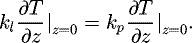 (23)
(23)
For the thermal analysis of CRCL, the thermal boundary conditions are needed, and they are given as follows [28]:
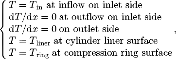 (24)
(24)
where Tring is the initial temperature of compression ring, Tliner is the initial temperature of cylinder liner, Tin is the inlet temperature of oil film. According to the work of Shahmohamadi et al. [29], the inlet temperature of oil film Tin is equal to the initial liner temperature Tliner. Therefore, the initial temperature of cylinder liner Tliner should be known a priori for the thermal analysis of CRCL.
2.6 Performance parameters
The friction force in CRCL ftotal consists of hydrodynamic friction force foil and asperity friction force fasp, and their expressions are given as follows [28]:
 (25)
(25)
 (26)
(26)
 (27)
(27)
where Φf, Φfs and Φfp are the friction-induced flow factors, Ω is the oil film area, τ0 is the shear stress constant, α0 is the asperity friction coefficient.
In order to evaluate the wear of CRCL, the wear load on the compression ring defined by Gulwadi [43] is calculated. It can be expressed as:
 (28)
(28)
where θc is the crankshaft angle, θ0 is 360° for a two-stroke ICE or 720° for a four-stroke ICE.
The power loss of CRCL can be evaluated as [28]:
 (29)
(29)
3 Results and discussion
3.1 Validation
Before studying the effects of compression ring wear and cylinder liner deformation on the thermal mixed lubrication performance of CRCL, it is necessary to verify the model used in our study. The validation has been made using Gu et al. [28] and our models. Figure 3 shows the oil film pressures on the middle cross-section of the compression ring calculated by Gu et al. [28] and our models under the same input parameters and working conditions. As shown in Figure 3, the oil film pressure predicted by the proposed model is in good agreement with the results of Gu et al. [28], which suggests the validation of the proposed model. In what follows, in order to provide insight into the effects of compression ring wear and cylinder liner deformation on the thermal mixed lubrication performance of CRCL, the minimum oil film thickness, friction force, wear load, and power loss are calculated by the presented model. Tables 1–3 provide all the necessary parameters for the performance analysis of CRCL. Figure 4 shows the velocity of compression ring and the cylinder pressure when the engine speed is 2000 r min−1.
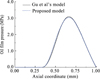 |
Fig. 3 Comparison between oil film pressures at the middle-cross section of compression ring obtained by present study and Gu et al. [28]. |
Engine parameters.
The parameters of oil 5W40.
Mechanical, thermal and surface properties of CRCL.
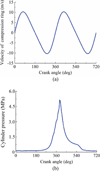 |
Fig. 4 Compression ring velocity and cylinder pressure when the engine speed is 2000 r min−1: (a) velocity of compression ring; (b) cylinder pressure. |
3.2 Influence of thermal effect
In order to illustrate the necessity of thermal effect in the lubrication performance analysis of roughness CRCL with axial-asymmetric new/worn compression ring and deformed cylinder liner, the minimum oil film thickness and friction under isothermal condition and thermal condition are calculated for various compression ring wear stages and cylinder liner deformations. For the convenience of comparative analysis, the differences of minimum oil film thickness, hydrodynamic friction, and asperity friction between isothermal analysis and thermal analysis are defined as:
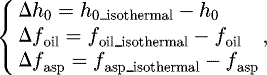 (30)
where Δh0, Δfoil, and Δfasp are the differences of minimum oil film thickness, hydrodynamic friction, and asperity friction between isothermal analysis and thermal analysis. h0_isothermal, foil_isothermal, and fasp_isothermal are the minimum oil film thickness, hydrodynamic friction, and asperity friction under isothermal condition.
(30)
where Δh0, Δfoil, and Δfasp are the differences of minimum oil film thickness, hydrodynamic friction, and asperity friction between isothermal analysis and thermal analysis. h0_isothermal, foil_isothermal, and fasp_isothermal are the minimum oil film thickness, hydrodynamic friction, and asperity friction under isothermal condition.
Figure 5 shows the differences of minimum oil film thickness at various wear stages of compression ring when the maximum deformation of cylinder liner Δc = 0 µm, 15 µm, 25 µm, and 35 µm, respectively. As can be seen in Figure 5, the oil film thermal effect has a great influence on the minimum oil film thickness. With the oil film thermal effect taken into consideration, the minimum oil film thickness is reduced, and the reduction of minimum oil film thickness is different at each wear stage of compression ring. The difference of minimum oil film thickness decreases with the increase of compression ring wear. The new compression ring is found to have larger difference of minimum oil film thickness, especially at the middle of intake (θc = 0° ∼ 180°), compression (θc = 180° ∼ 360°), and exhaust (θc = 540° ∼ 720°) strokes. Moreover, the difference of minimum oil film thickness decreases with the increase of the maximum deformation of cylinder liner, but the decrease is small. At power stroke (θc = 360° ∼ 540°), the clearance between the compression ring and the cylinder liner is small, the generated friction heat can be quickly conducted by the compression ring and the cylinder liner. Therefore, a small difference of minimum oil film thickness is observed for CRCL.
Figure 6 shows the differences of hydrodynamic friction and asperity friction for various maximum deformations of cylinder liner. As shown in Figures 6a, c and e, the oil film thermal effect has a great influence on the hydrodynamic friction of CRCL. With the oil film thermal effect taken into consideration, the hydrodynamic friction is reduced, and larger difference of hydrodynamic friction is concentrated at the middle of the strokes because of the high viscous shear of oil film. At power stroke, the maximum deformation of cylinder liner is found to have a great effect on the difference of hydrodynamic friction, and the difference of hydrodynamic friction decreases with the increase of maximum deformation of cylinder liner. However, the effect of cylinder liner maximum deformation on the difference of hydrodynamic friction is negligibly small at intake, compression, and exhaust strokes. Moreover, higher difference of hydrodynamic friction is also found for the embedded compression ring, especially at the middle of the power stroke. As shown in Figures 6b, d and f, the oil film thermal effect increased the asperity friction of CRCL, and it can be seen that the cylinder liner maximum deformation and compression ring wear have greatly influence on the difference of asperity friction. The difference of asperity friction increases with the increase of maximum deformation of cylinder liner. Compared with the new compression ring and embedded compression ring, smaller difference of asperity friction is observed for the run-in compression ring because of strong squeeze effect and small asperity contact area.
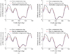 |
Fig. 5 Differences of minimum oil film thickness at various wear stages of compression ring: (a) Δc = 0 µm; (b) Δc = 15 µm; (c) Δc = 25 µm; (d) Δc = 35 µm. |
 |
Fig. 6 Differences of friction forces: (a) difference of hydrodynamic friction of new ring; (b) difference of asperity friction of new ring; (c) difference of hydrodynamic friction of run-in ring; (d) difference of asperity friction of run-in ring; (e) difference of hydrodynamic friction of embedded ring; (f) difference of asperity friction of embedded ring. |
3.3 Influence of compression ring wear and cylinder liner deformation
Based on the above discussion, it is demonstrated that the thermal effect of oil film has a great influence on the minimum oil film thickness and friction in CRCL. Therefore, the thermal effect of oil film should be considered in the analysis of CRCL to provide more detailed information about the frictional behaviors. In order to study the influence of compression wear and cylinder liner deformation on the tribological performance of CRCL, the minimum oil film thickness, friction, wear load, oil film temperature, and power loss are evaluated under thermal condition for various wear stages of compression ring and maximum deformations of cylinder liner.
Figure 7 shows the minimum oil film thickness in CRCL for different maximum deformations of cylinder liner. What is observed is that the minimum oil film thickness decreases with the increase of maximum deformation of cylinder liner, and the decrease is significant at the middle of the strokes. Moreover, it can be also seen that the lubrication regime of CRCL is changing from hydrodynamic lubrication (λ>4) to mixed lubrication (λ < 4) when the compression ring reaches near the dead centers at power stroke (θc = 360° or 540°). Compared with the new compression ring, smaller range of mixed lubrication regime is found for the run-in compression ring and the embedded compression ring, especially near the bottom dead center of power stroke (θc = 540°).
Figure 8 shows the hydrodynamic friction and asperity friction in CRCL for different maximum deformations of cylinder liner. From Figures 8a, c, and e, what is observed is that the difference of hydrodynamic friction between various maximum deformations of cylinder liner is negligibly small at intake, compression, and exhaust strokes. However, at power stroke, the hydrodynamic friction decreases with the increase of maximum deformation of cylinder liner, and lower hydrodynamic friction is observed for CRCL with embedded compression ring. As shown in Figures 8b, d, and f, it can be seen that the cylinder liner maximum deformation and compression ring wear have greatly influence on the asperity friction in CRCL. The asperity friction increases with the increase of maximum deformation of cylinder liner. Compared with the new compression ring and embedded compression ring, smaller asperity friction is observed for the run-in compression ring.
The deformation of cylinder liner changes the tribological performance of CRCL. Two important changes are the wear of compression ring and the thermal effect of oil film. In order to investigate the influence of cylinder liner deformation on the wear of compression ring and the thermal effect of oil film, the wear load of compression ring and the oil film temperature difference between deformed cylinder liner and circular cylinder liner are calculated. Figure 9a shows the peak values of wear load for different maximum deformations of cylinder liner. As can be seen in Figure 9a, the peak value of wear load on the compression ring is an increasing function of maximum deformation of cylinder liner, and the increasing rate decreases with the increase of cylinder liner maximum deformation. Compared with the new compression ring, lower peak values of wear load are observed for the run-in compression ring and embedded compression ring, especially for the run-in compression ring. The reason is that the asperity friction of run-in compression ring is lower. Figures 9b, c and d show the oil film temperature differences between deformed cylinder liner and circular cylinder liner for new compression ring, run-in compression ring, and embedded compression ring. What is observed is that the deformation of cylinder liner causes an increase of oil film temperature, but the increase is very small. Compared with new compression ring and run-in compression ring, lower increase of oil film temperature is observed for the embedded compression ring at power stroke.
Figure 10 shows the power loss of CRCL for different maximum deformations of cylinder liner. As can be seen in Figure 10, the cylinder liner maximum deformation has a less effect on the power loss of CRCL at intake, compression, and exhaust strokes. At power stroke, lower power loss is observed for the embedded compression ring, and the power loss of CRCL decreases with the increase of cylinder liner maximum deformation.
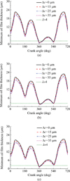 |
Fig. 7 Minimum oil film thicknesses in CRCL for different maximum deformations of cylinder liner: (a) new compression ring; (b) run-in compression ring; (c) embedded compression ring. |
 |
Fig. 8 Friction forces in CRCL for different maximum deformations of cylinder liner: (a) hydrodynamic friction of new ring; (b) asperity friction of new ring; (c) hydrodynamic friction of run-in ring; (d) asperity friction of run-in ring; (e) hydrodynamic friction of embedded ring; (f) asperity friction of embedded ring. |
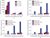 |
Fig. 9 (a) Peak value of wear load; (b) oil film temperature difference for new compression ring; (c) oil film temperature difference for run-in compression ring; (d) oil film temperature difference for embedded compression ring. |
 |
Fig. 10 Power losses of CRCL for different maximum deformations of cylinder liner: (a) new compression ring; (b) run-in compression ring; (c) embedded compression ring. |
4 Conclusion
In this paper, a thermal-mixed lubrication model is proposed to evaluate the lubrication performance of roughness CRCL with axial-asymmetric new/worn compression ring and deformed cylinder liner. The effects of cylinder liner deformation on the minimum oil film thickness, friction force, power loss, and wear in CRCL are analyzed for various compression ring wear stages. The related conclusions can be made as follows:
The oil film thermal effect has a great influence on the minimum oil film thickness and friction of CRCL. The difference of hydrodynamic friction between isothermal analysis and thermal analysis is a decreasing function of cylinder liner maximum deformation at power stroke. The difference of asperity friction between isothermal analysis and thermal analysis is an increasing function of cylinder liner maximum deformation. Compared with the new compression ring, smaller difference of minimum oil film thickness and frictions between isothermal analysis and thermal analysis are found for the embedded compression ring and the run-in compression ring.
The minimum oil film thickness decreases with the increase of maximum deformation of cylinder liner, but the decrease is very small at power stroke. The asperity friction, the peak value of wear load, and the oil film temperature increase with the increase of maximum deformation of cylinder liner. The cylinder liner maximum deformation is also found to have a great effect on the hydrodynamic friction and power loss of CRCL, especially at power stroke. Moreover, compared with the new compression ring, lower hydrodynamic friction and power loss are observed for the embedded compression ring, and lower asperity friction is observed for the run-in compression ring.
Finally, it is noteworthy that the lubrication condition in this study is assumed to be fully flooded. In practice, the lubrication condition of compression ring-cylinder liner system is not only fully flooded, but also starved in some points of their strokes because of scraping effect of oil control ring. The effect of compression ring wear and cylinder liner deformation on the lubrication performance of CRCL under starved lubrication condition is the subject of ongoing work with consideration of oil supply.
Nomenclature
a: Radial thickness of compression ring
A: Apparent contact area
Ac: Asperity contact area
b: Axial width of compression ring
cp: Oil specific heat capacity
cr: Specific heat capacity of compression ring
cl: Specific heat capacity of cylinder liner
Δc: Maximum deformation of cylinder liner
E: Young's modulus of compression ring
E': Equivalent elastic modulus of ring and liner
ftotal: Total friction force
Fasp: Asperity contact force
f asp: Asperity friction force
fasp_isothermal: Asperity friction under isothermal condition
Δfasp: Difference of asperity friction between isothermal analysis and thermal analysis
Fbp: Backpressure of compression ring
Ft: Tension force of compression ring
foil: Hydrodynamic friction force
foil_isothermal: Hydrodynamic friction under isothermal condition
Δfoil: Difference of hydrodynamic friction between isothermal analysis and thermal analysis
Foil: Oil film force
F2.5(λ), F2(λ): Statistic function
h: Oil film thickness
h0: Minimum oil film thickness
h0_isothermal: Minimum oil film thickness under isothermal condition
Δh0: Difference of minimum oil film thickness between isothermal analysis and thermal analysis
hring: The gap between ring and liner caused by the ring face profile
hliner: The gap between ring and liner caused by the liner deformation
l: Length of connecting rod
n: Order of cylinder liner deformation
p: Oil film pressure
pa: Ambient pressure
pasp: Asperity contact pressure
pc: Cavitation pressure
pl: Gas pressure under the compression ring
Ploss: Power loss
pt: Cylinder pressure
r: Nominal radius of cylinder liner
R: Radius of crankshaft
ΔR: Radius variation of cylinder liner caused by the liner deformation
t: Time
T: Temperature
T0: Oil temperature under atmospheric pressure
u: Oil velocity in x direction
U: Velocity of compression ring
Un: Elastic deformation of ring caused by the ring conformability
v: Oil velocity in y direction
Wload: Wear load of compression ring
x: Axial coordinate in global coordinate system
y: Circumferential coordinate in global coordinate system
z: Radial coordinate in global coordinate system
Greek symbols
α0: Asperity friction coefficient
β: Curvature radius of asperity
θ: Saturation of fluid
θc: Crankshaft angle
κ: Density of asperity
κp: Oil thermal conductivity
κr: Thermal conductivity of compression ring
κl: Thermal conductivity of cylinder liner
κvp: Oil viscosity-pressure coefficient
κvt: Oil viscosity-temperature coefficient
λ: Ratio of oil film thickness to comprehensive surface roughness
η: Oil viscosity
η0: Oil viscosity under atmospheric pressure
ρ: Oil density
ρ0: Oil density under atmospheric pressure
ρr: Density of compression ring
ρl: Density of cylinder liner
σring: Surface roughness of compression ring
σliner: Surface roughness of cylinder liner
σ: Comprehensive surface roughness of ring and liner
τ0: Shear stress constant
ω: Angular velocity of crankshaft
ϕ: Circumferential position
ϕn: Circumferential position of maximum liner deformation
Φf, Φfs, Φfp: Friction-induced flow factors
Φs: Shear flow factor
Φx, Φy: Pressure flow factors
Ω: Area of fluid film
Acknowledgements
The research work presented in this paper is supported by National Natural Science Foundation of China (Grant No. 51775428), Open Project of State Key Laboratory of Digital Manufacturing Equipment and Technology (Grant No. DMETKF2017014), Scientific Research Program of Shaanxi Provincial Education Department of China (Grant No. 15JS068), and Project of PhD Innovation Foundation of Xi'an University of Technology (Grant No. 310-252071701).
References
- C.M. Taylor, Automobile engine tribology-design considerations for efficiency and durability, Wear 221 (1998) 1–8 [CrossRef] [Google Scholar]
- E.P. Becker, Trends in tribological materials and engine technology, Tribol. Int. 37 (2004) 569–575 [CrossRef] [Google Scholar]
- P.C. Mishra, S. Balakrishnan, H. Rahnejat, Tribology of compression ring-to-cylinder contact at reversal, Proc. IMechE Part J: J. Eng. Tribol. 222 (2008) 815–826 [CrossRef] [Google Scholar]
- K. Holmberg, P. Andersson, A. Erdemir, Global energy consumption due to friction in passenger cars, Tribol. Int. 47 (2012) 221–234 [CrossRef] [Google Scholar]
- S.C. Tung, M.L. McMillan, Automotive tribology overview of current advances and challenges for the future, Tribol. Int. 37 (2004) 517–536 [CrossRef] [Google Scholar]
- G.G.A. Fatjo, E.H. Smith, I. Sherrington, Mapping lubricating film thickness, film extent and ring twist for the compression-ring in a firing internal combustion engine, Tribol. Int. 70 (2014) 112–118 [CrossRef] [Google Scholar]
- V.W. Wong, S.C. Tung, Overview of automotive engine friction and reduction trends-effects of surface, material, and lubricant-additive technologies, Friction 4 (2016) 1–28 [CrossRef] [Google Scholar]
- N.W. Bolander, B.D. Steenwyk, F. Sadeghi, G.R. Gerber, Lubrication regime transitions at the piston ring-cylinder liner interface, Proc. IMechE Part J: J. Eng. Tribol. 219 (2005) 19–31 [CrossRef] [Google Scholar]
- C. Baker, S. Theodossiades, R. Rahmani, H. Rahnejat, B. Fitzsimons, On the transient three-dimensional tribodynamics of internal combustion engine top compression ring, ASME J. Eng. Gas Turb. Power 139 (2017) 062801 [CrossRef] [Google Scholar]
- Y.R. Jeng, Theoretical analysis of piston-ring lubrication part I-fully flooded lubrication, Tribol. Trans. 35 (1992) 696–706 [CrossRef] [Google Scholar]
- G.A. Livanos, N.P. Kyrtatos, Friction model of a marine diesel engine piston assembly, Tribol. Int. 40 (2007) 1441–1453 [CrossRef] [Google Scholar]
- R.I. Taylor, Squeeze film lubrication in piston rings and reciprocating contacts, Proc. IMechE Part J: J. Eng. Tribol. 229 (2015) 977–988 [CrossRef] [Google Scholar]
- A. Usman, C.W. Park, Transient lubrication of piston compression ring during cold start-up of SI engine, Int. J. Pr. Eng. Man. Gt. 3 (2016) 81–90 [Google Scholar]
- T. Hamatake, Y. Wakuri, M. Soejima, T. Kitahara, Effects of lubricant viscosity on the mixed lubrication of a piston ring pack in an internal combustion engine, Lubri. Sci. 15 (2003) 101–117 [CrossRef] [Google Scholar]
- M.K.A. Ali, X.J. Hou, R.F. Turkson, M. Ezzat, An analytical study of tribological parameters between piston ring and cylinder liner in internal combustion engines, Proc. IMechE Part K: J. Multi-body Dyn. 230 (2016) 329–349 [Google Scholar]
- P. Obert, T. Müller, H.J. Füßer, D. Bartel, The influence of oil supply and cylinder liner temperature on friction, wear and scuffing behavior of piston ring cylinder liner contacts-a new model test, Tribol. Int. 94 (2016) 306–314 [CrossRef] [Google Scholar]
- R. Rahmani, H. Rahnejat, B. Fitzsimons, D. Dowson, The effect of cylinder liner operating temperature on frictional loss and engine emissions in piston ring conjunction, Appl. Energ. 191 (2017) 568–581 [CrossRef] [Google Scholar]
- F.J. Profito, E. Tomanik, D.C. Zachariadis, Effect of cylinder liner wear on the mixed lubrication regime of TLOCRs, Tribol. Int. 93 (2016) 723–732 [CrossRef] [Google Scholar]
- Z.N. Zhang, J. Liu, Y.B. Xie, Design approach for optimization of a piston ring profile considering mixed lubrication, Friction 4 (2016) 225–346 [Google Scholar]
- Y. Piao, S.D. Gulwadi, Numerical investigation of the effects of axial cylinder bore profiles on piston ring radial dynamics, ASME J. Eng. Gas Turb. Power 125 (2003) 1081–1089 [CrossRef] [Google Scholar]
- G. Styles, R. Rahmani, H. Rahnejat, B. Fitzsimons, In-cycle and life-time friction transience in piston ring-liner conjunction under mixed regime of lubrication, Int. J. Engine Res. 15 (2014) 862–876 [CrossRef] [Google Scholar]
- P.C. Mishra, Tribodynamic modeling of piston compression ring and cylinder liner conjunction in high-pressure zone of engine cycle, Int. J. Adv. Manuf. Technol. 66 (2013) 1075–1085 [CrossRef] [Google Scholar]
- M.T. Ma, I. Sherrington, E.H. Smith, N. Grice, Development of a detailed model for piston-ring lubrication in IC engines with circular and non-circular cylinder bores, Tribol. Int. 30 (1997) 779–788 [CrossRef] [Google Scholar]
- N. Morris, R. Rahmani, H. Rahnejat, P.D. King, B. Fitzsimons, The influence of piston ring geometry and topography on friction, Proc. IMechE Part J: J. Eng. Tribol. 227 (2013) 141–153 [CrossRef] [Google Scholar]
- W.W.F. Chong, S. Howell-Smith, M. Teodorescu, N.D. Vaughan, The influence of inter-ring pressures on piston-ring/liner tribological conjunction, Proc. IMechE Part J: J. Eng. Tribol. 227 (2013) 154–167 [CrossRef] [Google Scholar]
- A. Usman, T.A. Cheema, C.W. Park, Tribological performance evaluation and sensitivity analysis of piston ring lubricating film with deformed cylinder liner, Proc. IMechE Part J: J. Eng. Tribol. 229 (2015) 1455–1468 [CrossRef] [Google Scholar]
- A. Usman, C.W. Park, Numerical investigation of frictional behavior and energy loss in mixed-hydrodynamic contact of piston ring pack with deformed cylinder liner during warm-up period of SI-engine, Energ. Convers. Manag. 117 (2016) 115–131 [CrossRef] [Google Scholar]
- C.X. Gu, X.H. Meng, Y.B. Xie, J.Z. Fan, A thermal mixed lubrication model to study the textured ring/liner conjunction, Tribol. Int. 101 (2016) 178–193 [CrossRef] [Google Scholar]
- H. Shahmohamadi, R. Rahmani, H. Rahnejat, C.P. Garner, P.D. King, Thermo-mixed hydrodynamics of piston compression ring conjunction, Tribol. Lett. 51 (2013) 323–340 [CrossRef] [Google Scholar]
- C. Lenauer, C. Tomastik, T. Wopelka, M. Jech, Piston ring wear and cylinder liner tribofilm in tribotests with lubricants artificially altered with ethanol combustion products, Tribol. Int. 82 (2015) 415–422 [CrossRef] [Google Scholar]
- L. Ba, Z.P. He, L.Y. Guo, Y. Chiang, G.C. Zhang, X. Lu, Piston ring-cylinder liner tribology investigation in mixed lubrication regime: part I-correlation with bench experiment, Ind. Lubr. Tribol. 67 (2015) 520–530 [CrossRef] [Google Scholar]
- G.C. Buscaglia, M. Jai, A new numerical scheme for non uniform homogenized problems: application to the non linear Reynolds compressible equation, Math. Probl. Eng. 7 (2001) 355–378 [CrossRef] [Google Scholar]
- D. Gropper, L. Wang, T.J. Harvey, Hydrodynamic lubrication of textured surfaces: a review of modeling techniques and key findings, Tribol. Int. 94 (2016) 509–529 [CrossRef] [Google Scholar]
- N. Patir, H.S. Cheng, An average flow model for determining effects of three-dimensional roughness on partial hydrodynamic lubrication, ASME J. Lubr. Technol. 100 (1978) 12–17 [Google Scholar]
- C.X. Gu, X.H. Meng, Y.B. Xie, D. Zhang, Mixed lubrication problems in the presence of textures: an efficient solution to the cavitation problem with consideration of roughness effects, Tribol. Int. 103 (2016) 516–528 [CrossRef] [Google Scholar]
- Y. Mao, L.C. Zeng, Y. Lu, Modeling and optimization of cavitation on a textured cylinder surface coupled with the wedge effect, Tribol. Int. 104 (2016) 212–224 [CrossRef] [Google Scholar]
- L. Bobach, R. Beilicke, D. Bartel, L. Deters, Thermal elastohydrodynamic simulation of involute spur gears incorporating mixed friction, Tribol. Int. 48 (2012) 191–206 [CrossRef] [Google Scholar]
- C.W. Wu, L.Q. Zheng, An average Reynolds equation for partial film lubrication with a contact factor, ASME J. Tribol. 111 (1989) 188–191 [CrossRef] [Google Scholar]
- N. Morris, M. Mohammadpour, R. Rahmani, P.M. Johns-Rahnejat, H. Rahnejat, D. Dowson, Effect of cylinder deactivation on tribological performance of piston compression ring and connecting bearing, Tribol. Int. (2018) DOI:10.1016/j.triboint.2017.12.045 [Google Scholar]
- H.M. Checo, A. Jaramillo, R.F. Ausas, G.C. Buscaglia, The lubrication approximation of the friction force for the simulation of measured surfaces, Tribol. Int. 97 (2016) 390–399 [CrossRef] [Google Scholar]
- C.X. Gu, X.H. Meng, Y.B. Xie, X.L. Kong, Performance of surface texturing during start up under starved and mixed lubrication, ASME J. Tribol. 139 (2017) 011702 [Google Scholar]
- X.L. Liu, X.R. Bai, J.L. Cui, P.R. Yang, Thermal elastohydrodynamic lubrication analysis for tilted and skewed rollers in cylindrical roller bearings, Proc. IMechE Part J: J. Eng. Tribol. 230 (2016) 428–441 [CrossRef] [Google Scholar]
- S.D. Gulwadi, Analysis of tribological performance of a piston ring pack, Tribol. Trans. 43 (2000) 151–162 [CrossRef] [Google Scholar]
Cite this article as: C. Liu, Y. Lu, P. Wang, Y. Zhang, Y. Zhang, N. Müller, Numerical analysis of the effects of compression ring wear and cylinder liner deformation on the thermal mixed lubrication performance of ring-liner system, Mechanics & Industry 19, 203 (2018)
All Tables
All Figures
|
Fig. 1 Schematic diagram of CRCL. |
| In the text | |
|
Fig. 2 (a) Face profiles of new compression ring, run-in compression ring, and embedded compression ring; (b) schematic diagram of deformed cylinder liner and compression ring conformability [27]. |
| In the text | |
|
Fig. 3 Comparison between oil film pressures at the middle-cross section of compression ring obtained by present study and Gu et al. [28]. |
| In the text | |
|
Fig. 4 Compression ring velocity and cylinder pressure when the engine speed is 2000 r min−1: (a) velocity of compression ring; (b) cylinder pressure. |
| In the text | |
|
Fig. 5 Differences of minimum oil film thickness at various wear stages of compression ring: (a) Δc = 0 µm; (b) Δc = 15 µm; (c) Δc = 25 µm; (d) Δc = 35 µm. |
| In the text | |
|
Fig. 6 Differences of friction forces: (a) difference of hydrodynamic friction of new ring; (b) difference of asperity friction of new ring; (c) difference of hydrodynamic friction of run-in ring; (d) difference of asperity friction of run-in ring; (e) difference of hydrodynamic friction of embedded ring; (f) difference of asperity friction of embedded ring. |
| In the text | |
|
Fig. 7 Minimum oil film thicknesses in CRCL for different maximum deformations of cylinder liner: (a) new compression ring; (b) run-in compression ring; (c) embedded compression ring. |
| In the text | |
|
Fig. 8 Friction forces in CRCL for different maximum deformations of cylinder liner: (a) hydrodynamic friction of new ring; (b) asperity friction of new ring; (c) hydrodynamic friction of run-in ring; (d) asperity friction of run-in ring; (e) hydrodynamic friction of embedded ring; (f) asperity friction of embedded ring. |
| In the text | |
|
Fig. 9 (a) Peak value of wear load; (b) oil film temperature difference for new compression ring; (c) oil film temperature difference for run-in compression ring; (d) oil film temperature difference for embedded compression ring. |
| In the text | |
|
Fig. 10 Power losses of CRCL for different maximum deformations of cylinder liner: (a) new compression ring; (b) run-in compression ring; (c) embedded compression ring. |
| In the text | |
Current usage metrics show cumulative count of Article Views (full-text article views including HTML views, PDF and ePub downloads, according to the available data) and Abstracts Views on Vision4Press platform.
Data correspond to usage on the plateform after 2015. The current usage metrics is available 48-96 hours after online publication and is updated daily on week days.
Initial download of the metrics may take a while.