| Issue |
Mechanics & Industry
Volume 19, Number 3, 2018
|
|
|---|---|---|
| Article Number | 313 | |
| Number of page(s) | 12 | |
| DOI | https://doi.org/10.1051/meca/2018025 | |
| Published online | 04 October 2018 | |
Regular Article
Simulation of incremental forming processes of a pyramidal ring made of two materials
School of Mechanical Engineering, Iran University of Science and Technology,
Tehran, Iran
* e-mail: This email address is being protected from spambots. You need JavaScript enabled to view it.
Received:
21
January
2018
Accepted:
27
April
2018
Abstract
Incremental forming is one of the most well-known forming processes for complex and asymmetric parts. This method uses a CNC machine, simple forming tool, and a die. This study focused on effects of some parameters such as the material, feed rate, pitch, rotational speed and movement strategy of tool on the dimensional precision, forming force, thickness distribution and fracture in the welding area. The results showed that single point incremental forming (SPIF) led to a better thickness distribution with lower tool force, whereas two-point incremental forming led to better dimensional accuracy. Rotational speed does not have any significant impact on the forming process while decreasing the feed rate partially reduced the forming force. According to the results, although dimensional precision in double point incremental forming is better than SPIF, when it comes to the thickness distribution, forming force, and economic issues, SPIF is in favor. The results also showed that by connecting two materials, different parameters for the two materials could be investigated simultaneously in one simulation process.
Key words: Incremental forming / single point incremental forming / double point incremental forming / finite element method / simulation of a two-material-sheet
© AFM, EDP Sciences 2018
1 Introduction
In this fast-paced world, it is reasonable for the industry to seek fast, economical, and high quality approaches for forming parts. In modern approaches, not only have needs for different shapes been increased, but also the cost of manufacturing has decreased significantly. Additionally, conventional methods are in a great need for dies.
Incremental forming is one of the most practical rapid prototyping methods. This process is carried out using a CNC machine and a tool with a spherical head to make local plastic forming on the sheet. There are two contacts in this method, namely the single point and double point contact.
Jeswiet [1] described important parameters in incremental forming and also developed a new strategy for the movement of the tool. Kopac and Kampus [2] introduced and compared two strategies of inner and outer movement of the tool. They reported that the inner movement of the tool makes a more precise (lower surface brittleness) forming. Duflou et al. [3] used a multi-step toolpath strategy for single point incremental forming (SPIF). Attanasio et al. [4] could improve dimensional precision and surface quality and decreased the sheet thinning phenomenon by optimizing the tool path in the double point incremental forming (DPIF) with a spiral movement strategy. Araghi et al. [5] developed a new hybrid process, a combination of asymmetric incremental sheet forming and stretch forming. Using this process, the thickness distribution of the sheet was improved. Moreover, the time required for forming was cut down. Yonjuan Wang et al. [6] showed that in DPIF, formed plate thickness follows the Cosine law, and the initial thickness influences the angle of the cone. Malhotra et al. [7] used a second tool as a supporting tool in DPIF, because the more the pressure on the sheet is, the better thickness distribution will be achieved. In DPIF and hybrid forming which are vastly used these days, more complicated parts can be fabricated if a die is used as well. They indicated that DPIF leads to a higher dimensional precision than SPIF, due to the larger contact between the sheet and the tool. Malhotra et al. [8] suggested a novel accumulative double sided incremental forming (ADSIF) which implements a new tool movement strategy. Rui Xu et al. [9] observed that a part formed by ADSIF showed better fatigue performance than a virgin material. Sedighi et al. [10] presented an analytical method based on both upper bound and slip lines approaches to predict the incremental punching process. Asgari et al. [11] evaluated the effects of hammering frequency and tool radius on the mechanical properties of aluminum sheets in incremental sheet metal hammering process. Asgari et al. [12] designed and developed an incremental forming process using hammering and mass damper, which led to better surface quality. They also took the geometry, thickness, surface quality and spring-back under investigation. They reported that the surface roughness and spring-back decreased by increasing the punch diameter [13]. Asghari et al. [14] examined the effects of parameters of DPIF, such as tool nose diameter, wall angle, rotational speed and deep step, on the minimum thickness, surface quality, and spring-back. Zhang et al. [15] introduced a hybrid multi-point incremental forming process which resulted in improving the properties of the final part. Davarpanah et al. [16] studied the results of forming a plate made of PVC using DPIF and SPIF. They came to conclusion, by studying the forming force and structure of the formed polymer void, which the DPIF method leads to more accurate results. Tandon and Sharma [17] overcome the limits on the forming depth and the wall angle, to a reasonable extent, by combining incremental forming and tension. Ben Said et al. [18] optimized four movement strategies of the tool for favorable thickness and forming force by considering the elastic-plastic model and subroutine coding to form a square geometry. Boudhaouia et al. [19] examined the required forming force and final part quality of a plate formed with spiral movement strategy of the tool through experimental and numerical work. Bansal et al. [20] knowing the importance of the geometrical accuracy, plate thickness, plate-tool relations and forming force, introduced an analytical model which was able to predict the plate thickness and forming force through DPIF and SPIF. Otsu et al. [21] formed cones with different wall angles out of a plate made of an aluminum alloy through SPIF and DPIF. They observed that DPIF can make better shapes, in particular in terms of the cross-section shape. Suresh et al. [22] have overcome the disadvantages of SPIF in forming some certain angles by introducing a number multi-stage incremental forming methods. As a result, they could form cylindrical, spherical and square shapes with critical angles. McAnulty et al. [23] consulted 35 scientific papers to provide a comprehensive review study of the effects of parameters such as material thickness, tool diameter, type and shape of the tool, rotational speed and direction, feed rate and pitch on the results of SPIF. Memicoglu et al. [24] introduced a few models for simulation of incremental forming which gave rise to a 24-fold and 8% decrease in the processing time and errors. Lu et al. [25] regarding the relative low accuracy of SPIF, utilized a model predictive control approach and DPIF with partial die and improved the forming accuracy and plate thickness. Min et al. [26] performed DPIF to form a plate made of metallic foam and enhanced the forming accuracy, regarding the natural characteristics of the material. Shamsari et al. [27] carried out a two-step incremental forming approach to make a conical frustum. First, a part of the forming was performed through fluid pressure and then the rest of the forming was carried out accurately using the suitable forming tool. They improved the forming depth and plate thinning coefficient through the combined approach. Mirnia et al. [28] studied the ductile damage behavior of cones made of Al alloys formed using three two-step incremental forming approaches. They investigated the parameters which affected the failure analysis. Barnwal et al. [29] conducted a microstructural study of Al-6061, with high strength/weight ratio, which is widely used in automobile and aerospace industry. They examined different strains made during SPIF.
This paper presents the effects of being two-material-rectangular (pyramidal) ring on the dimensional precision, thickness distribution, forming force, and fracture in the welding regions and the sheet by changing parameters, which has not been completely evaluated in the previous researches. Parameters which affect the four mentioned properties are: movement strategy of the tool, whether to use SPIF or DPIF approach, rotational speed, feed rate, pitch size and sheet material. Using a sheet which each half of it is made of a different type of material, it is possible to examine the quality of forming two materials simultaneously by conducting one experiment. Also geometry of a pyramidal ring, with an inner and outer wall, will lead to a better study.
2 Materials and methods
In this research, Abaqus software was used for simulation. The sheet is made of two different materials of aluminum 1200 (high-ductile) and steel 304 (low-ductile). It was assumed that the two halves of the sheet are connected to each other by a weld joint and have made a uniform sheet. The geometry used in this work was a pyramidal ring, and the simulation parameters are presented in Table 1. Since the geometry was modeled as a shell and an explicit finite element approach is utilized, S4R elements (four-node shell element) with 1 mm size was used [30]. All the edges were fixed, and the diameter of the tool was 5 mm. A schematic of SPIF and DPIF is shown in Figure 1a and b.
In previous works, either a supporting tool or an upside-down die has been used for DPIF, as shown in Figure 1c. In case of using a die, the outer surface of the sheet is fixed only horizontally. However, in this work, as shown in Figure 1b, both the outer and inner areas were fixed in all directions to have an innovative DPIF (see Fig. 1b).
Since there is a clear need for mass scaling, due to the long time of the simulation of incremental forming, a mass scaling factor of 1000 was chosen, by using the trial and error method. According to the amounts of ratios of internal energy to kinetic one and internal energy to total one, static modeling of the simulation process was confirmed. It is worthwhile to mention that for a part of simulations, due to the high number of contacts between surfaces, the mass scaling factor was chosen 10 000. Correlation of the tool force for the modeling with two mass scaling factors of 1000 and 10 000 shows that there is no problem with using different mass scaling factors (see Fig. 2). It should be noted that the noise in reporting the tool force is inevitable in explicit finite element approach.
Simulation parameters.
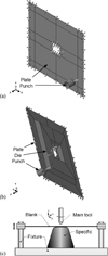 |
Fig. 1 Schematic incremental forming: (a) single point incremental forming (SPIF), (b) double point incremental forming (DPIF), (c) DPIF with an upside-down die. |
 |
Fig. 2 Tool force using two different mass scaling factor of 1000 and 10 000. |
3 Results and discussion
3.1 Effective parameters on dimensional precision
3.1.1 Movement strategy
Four tool movement strategies were investigated, in this work. The tool path was spiral for all movement strategies, as it leads to better results in quality [30]. In the first movement strategy, first, the outer wall and then the inner wall is formed (see Fig. 3a). While in the second movement strategy (see Fig. 3b), the tool also passes the pyramidal ring bottom after forming the inner wall. In the third strategy, first the inner wall and the outer wall is formed (see Fig. 3c). Whereas, in the fourth strategy, the tool also passes the pyramidal ring bottom after forming the outer wall (see Fig. 3d). It can be seen from Figure 4a, which shows SPIF results, that the second and fourth strategies, especially the second, led to better results, due to the longer tool path. However, owing to the importance of time for simulation, the first strategy was selected as the basis for simulation out of the first and the third strategies.
It can be seen from Figure 4b, which shows DPIF results, that the aforementioned facts about SPIF with different movement strategies are also true about DPIF with the same movement strategies. As predictable, DPIF products were of better quality especially on the top edges, because of the supportive die under the sheet. Due to the high cost of producing dies, SPIF still is favored over DPIF. After all, DPIF with the second movement strategy can be named as the best approach, in terms of dimensional precision.
It should be noted that in forming the inner wall, the tool was closer to the edge of the sheet compared to forming the outer wall; this is why forming the inner wall was more favorable, the fracture is more likely around the edge nonetheless. Therefore, the best distance to the edge should be attained.
There is a bump with the height of less than 5 mm in the central part of the ring due to spring back behavior of the sheet. While the there is no bump around the edge of the sheet, thanks to the stronger plastic behavior there.
Figure 5 shows the final state of the basic simulation. The weld line and the direction perpendicular to it can be seen in Figure 5. According to Figure 5 and the starting and ending point of the path, since the tool path was spiral, the final shape was close to the favorable shape. As a result, better quality in diagrams in the direction of the weld line for the second hole is explainable.
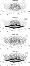 |
Fig. 3 Movement strategy: (a) first strategy, (b) second strategy, (c) third strategy, (d) fourth strategy. |
 |
Fig. 4 Dimensional precision for the two forming methods and different strategies: (a) dimensional precision achieved by SPIF, (b) dimensional precision achieved by DPIF. |
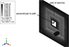 |
Fig. 5 The final state of the simulation, the weld line and the direction perpendicular to it. |
3.1.2 Rotational speed
The effect of the rotational speed can be seen in Figure 6a by comparing the results at 0, 50, 100, and 400 rpm counterclockwise. As seen in Figure 6a, the rotational speed does not influence the dimensional precision. Therefore, in order to save energy, no rotation was used in the simulation process.
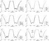 |
Fig. 6 Dimensional precision: (a) dimensional precision at different rotational speeds, (b) dimensional precision with different feed rates, (c) dimensional precision with different pitch sizes, (d) dimensional precision in the direction perpendicular to the weld line with different pitch sizes, (e) dimensional precision for different materials, (f) dimensional precision for different materials in the direction perpendicular to the weld line. |
3.1.3 Feed rate
The dimensional precision with different feed rates of 500, 800, and 1000 mm/min can be seen in Figure 6b since the feed rate as no effect on the dimensional precision, it was chosen 1000 in order to have a faster simulation.
3.1.4 Pitch
Figure 6c shows the dimensional precision with respect to the pitch size. The pitch size was chosen 0.5, 0.7, and 1 mm. Since there is a direct relationship between the pitch and the spring back, the dimensional precision was decreased by increasing the pitch. As a result, the pitch was chosen 0.5 mm in the simulation process.
It must be mentioned that all the diagrams were achieved in the weld line direction, as this research focuses on the presence of the weld and its effect on DPIF and SPIF. Indeed, the holistic concept of the mentioned facts are true in the direction perpendicular to the weld line. As seen in Figure 6d, although the dimensional precision was better for the left hole, it is just because in this direction, the forming started on the half made of steel, and continued on the half made of aluminum, which led to less forming in the half made of aluminum, consequently.
3.1.5 Material
In order to study the effect of the material on the dimensional accuracy, three different sheets made of aluminum, steel, and aluminum–steel were simulated (see Fig. 6e). For the aluminum sheet, due to its lower strength, better dimensional precision was achieved as a result, although it was hampered in the corners of the hole, due to the high plastic behavior of the aluminum sheet there.
The reasonable correlation between the left holes of the steel and aluminum–steel sheet, and the right holes of the aluminum and aluminum–steel sheet confirms that simulation of a single sheet made of two materials can be used instead of simulation of two sheets made of two materials to lower the simulation time (see Fig. 6f).
The spring-back of steel sheets at the end of the forming process is more than aluminum spring-back, owing to the high plastic behavior of the aluminum there. In all of the diagrams, the spring-back at the corner of the inner wall is more than the outer wall of the ring. The reason underlying this phenomenon is that in the selected tool path, when the tool passes the inner wall, the outer wall is brought down a little, simultaneously with forming the inner wall. Thus, the maximum depth in the corner of the outer wall exceeded the ideal depth.
3.2 Effective parameters on the thickness distribution
3.2.1 Movement strategy
As seen in Figure 7a which symmetry is clear in it, for the forming process with the third and fourth movement strategies, the second peak in thickness is larger, because the forming process started from the central region of the sheet. However, there is a contrary behavior for the forming process with the first and second movement strategies. In conclusion, the thickness distribution was more favorable using the first and second movement strategies since the longer path at the beginning of the forming process led to higher formability and in turn the better thickness uniformity.
Since Abaqus determines the thickness of the sheet based on elements and the weld line consists of a set of nodes, the software measures the thickness of the adjacent elements. Due to the fact that the material of the sheet is different on two sides of the weld line, the thickness in direction of the weld line reported by the software looks like a zigzag path (see Fig. 7b). As studying the thickness of the welding material is not one of the objectives of this work, the thickness distributions were reported in the direction perpendicular to the weld line.
In DPIF, the thickness of the sheet must be expected to be lower, since the sheet is under compression on two sides (see Fig. 7c).
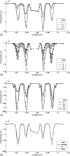 |
Fig. 7 Thickness distribute: (a) thickness distribute on of SPIF with different movement strategies in the direction perpendicular to the weld line, (b) thickness distribution in weld line direction by SPIF with different movement strategies, (c) thickness distribution by DPIF for different movement strategies, (d) thickness distribution for different materials. |
3.2.2 Rotational speed
Rotational speed is not effective when it comes to the thickness distribution, just like the dimensional precision.
3.2.3 Feed rate
Feed rate has no effect on the thickness distribution, just like the dimensional precision.
3.2.4 Material
It can be seen from Figure 7d that the thickness of the outer wall is higher than the thickness of the inner wall of the ring. Also, the thickness distribution of the half made of steel is more uniform, thanks to its higher strength.
3.3 Effective parameters on the forming tool force
3.3.1 Movement strategy
Since the sheet is made of two materials, the tool force must show a sinusoidal behavior along the tool path, which the maximum amount must be for the half made of steel, thanks to its higher strength. Moreover, due to the increasing resistance of the sheet to forming by going deeper, the tool force must also be increasing (see Fig. 8a). It should be noted that the tool path is the same in a part of the diagram for the first and second movement strategy, and there must be a complete correlation between the tool force curves in those parts for the third and fourth movement strategies.
As can be seen in Figure 8a, the tool is in no contact with the sheet at some moments for positioning to continue the forming process, and the tool force is zero at those moments. It can also be extracted from Figure 8a that the required force is higher in a smaller period of time for the forming process with the third and fourth movement strategies because the tool path starts from the inner borders, and this makes the sheet to show higher resistance when it comes to forming. Therefore, it can be confirmed again that the first and second strategies are better choices.
Since the force-time diagrams show many ups and downs, which is an inseparable part of explicit finite element method, the average force-time curves were used in this work in order to have high-quality curves. The last part of the tool path with the second and fourth strategies for forming of the ring bottom which requires a low amount of force makes the average force of the forming process with these strategies lower than the first and third ones (see Fig. 8b). Whereas, as mentioned before and shown in Figure 8a, the required average force with the first and second strategies are lower. Furthermore, some of the previous papers [31] used force-depth curves to study the forming force. Likewise, they were reported in this work and can be seen in Figure 8c.
The horizontal force applied to the tool, which is driven from  , were also studied and reported in Figure 8d. Although the horizontal force with the first and second strategies are higher than that with the third and fourth strategies, the first and second ones are still better options due to following reasons: (1) the difference between the horizontal forces are much lower than that between vertical forces, (2) the vertical point is usually the only important component of force in metal forming.
As seen in Figure 8e, DPIF required higher force due to the interaction between the tool and the die, especially in the course of forming the pyramidal ring bottom.
Another point which can be seen in all force-time curves is the same time of forming with the first and third, and with the second and fourth strategies, because of the same distance passes during forming. As seen in Figure 8e and f, the average vertical and horizontal DPIF force with different strategies are in the same order, in contrast to vertical and horizontal SPIF force (see Fig. 8c and d).
 |
Fig. 8 The forming force: (a) the vertical force for the forming process with different movement strategies, (b) average vertical SPIF force with different movement strategies, (c) average vertical SPIF force with different movement strategies with respect to the forming depth, (d) average horizontal SPIF force with different movement strategies, (e) average vertical DPIF force with different movement strategies, (f) average horizontal DPIF force with different movement strategies, (g) vertical forming force with different rotational speeds, (h) average vertical forming force with different feed rates, (i) average horizontal forming force with different feed rates, (j) average vertical forming force with different sizes of the pitch, (k) average horizontal forming force with different sizes of the pitch, (l) vertical forming force for different materials, (m) horizontal forming force for different materials. |
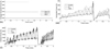 |
Fig. 8 continued. |
3.3.2 Rotational speed
As can be seen in Figure 8g, the rotational speed does not affect the vertical forming force.
3.3.3 Feed rate
As can be seen in Figure 8h and i, the feed rate does not have a considerable effect on the vertical or horizontal forming force; the differences were so small. After all, because the speed of the forming process is important, choosing a feed rate of 1000 mm/min can be confirmed again.
3.3.4 Pitch
It is clear from Figure 8j and k that there is a direct relationship between the pitch and the vertical force.
3.3.5 Material
As mentioned before and can be seen in Figure 8l and m, the force diagrams show sinusoidal behavior, due to the fact that the sheet is made of two different materials. Additionally, the force diagrams for the parts of the sheets that are made of the same material matched completely (e.g. the half made of aluminum and the sheet fully made of aluminum).
3.4 Effective parameters on fracture
According to the properties of welding two different materials, which usually friction-permeation is used, the weld strength is lower than the adherents [32]. Von Mises stress criterion is a way to investigate fracture in experimental works. In this work, the von Mises stress diagram was used in order to study fracture in weld line direction. Regarding the mentioned discussion, there are two amounts of stress at each point. Hence, the average of them was used to inspect the effects of different parameters on fracture (see Fig. 9a). As can be seen in Figure 9a and b, the hole present in the sheet led to a non-frequent part in the middle of the stress diagram, which after averaging the amounts of stress, the diagram went far away from reality. As a result, that part of the diagram was not considered in the analysis.
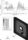 |
Fig. 9 Stress: (a) von Mises stress, (b) stress distribution. |
3.4.1 Movement strategies
As seen in Figure 10a, due to the longer tool path of forming with the second and fourth movement strategies, the average stress and its entire amount are lower with these movement strategies than with the first and third movement strategies, respectively. Also, the forming process with the first and second strategies are more critical, and the third and fourth ones are in priority in fracture analysis. Although subtle, the discussion is also true for DPIF (see Fig. 10b).
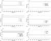 |
Fig. 10 Average stress: (a) average SPIF stress with different strategies, (b) average DPIF stress with different strategies, (c) average stress at different rotational speeds, (d) average stress with different feed rates, (e) average stress with different sizes of the pitch, (f) average stress of sheets made of different materials. |
3.4.2 Rotational speed
As seen in Figure 10c, rotational speed is not effective on the stress.
3.4.3 Feed rate
As seen in Figure 10d, it can be mentioned that with increasing the feed rate, the part is farther from fracture, its effect is little nonetheless.
3.4.4 Pitch
As seen in Figure 10e, although the pitch has not a noticeable effect, there is a direct relationship between the pitch size and the stress.
3.4.5 Material
As can be seen in Figure 10f, thanks to the higher strength of steel, the steel sheet is under a higher average stress than the aluminum–steel sheet and aluminum sheet.
3.5 Validation of the simulation
The experimental results presented in the literature [31], which has the closest geometry (see Fig. 11a and b) to the computer model in this work, was used in order to validate the simulations. The experiment was conducted on a sheet of aluminum-1200, and a ring with a 70 mm × 70 mm crosshead and 10 mm depth was fabricated out of it. The other parameters are the same as the simulation model in this work.
As seen in Figure 12a and b, the good correlation between vertical forming forces with a feed rate of 500 mm/min with respect to depth is evident, especially in the beginning of the forming process. As the beginning of the forming force diagram, versus depth, achieved by the numerical modeling and the experiment matched well, the small difference between the diagrams can be attributed to the use of lubricant in the experimental work. Since the tool has been heated after the beginning of the forming process, the presence of the lubricant, which was not considered in computational modeling, has made the difference between the diagrams.
 |
Fig. 11 Validation: (a) the specimen used in reference [31], (b) final geometry of the simulation with the parameters of reference [31]. |
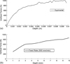 |
Fig. 12 Vertical forming force (validation): (a) vertical forming force versus depth achieved by numerical work, (b) vertical forming force versus depth reported by reference [31]. |
4 Conclusion
-
DPIF with the first and second movement strategies showed the best dimensional precision, especially the second one when the simulation time is not important. However, due to the weakness of DPIF in thickness distribution, higher required forming force and economic issues, SPIF is in favor;
-
since the distance to the edge of the sheet is longer at the beginning of the forming process with the first and second movement strategies, the sheet resistance to forming is lower which led to better thickness distribution;
-
although SPIF with the third and fourth movement strategies performed better when it comes to fracture, SPIF with the first or second movement strategies is recommended;
-
rotational speed showed no effect on any of the parameters, so no rotational speed was used for energy saving;
-
by increasing the feed rate, vertical and horizontal forming forces grew merely a small amount. Owing to the fact other parameters were not affected by fluctuating the feed rate, and because the speed of simulation is in priority, the feed rate was chosen 1000 mm/min;
-
the required forming force and von Mises stress rose by increasing the pitch size, due to the increase in stiffness produced by the applied strain. Also, a direct relationship between the vertical pitch size and the spring back was observed, which is not favorable for achieving the ideal geometry;
-
studying the effects of different parameters in this work showed that it is possible to analyze two sheets of different materials by only simulating one sheet made of two materials. A more favorable final geometry was achieved for the aluminum half, thanks to the dominating effect of plastic behavior over spring back of the aluminum sheet. Whereas, the steel half, owing to its high strength, showed better performance in thickness distribution. Last but not least, the aluminum sheet was quite safer when it comes to fracture, because it required less forming force as result of more ductility.
In this article, the ability to design properly based on industrial needs, such as production cost, time, accuracy, and quality is provided by a full parametric study on the incremental forming method. In other words, a designer could select the best production parameters regarding the industrial limitations and desired final part quality.
5 Acknowledgment
The authors would like to thank Hosein Ghasemi and Mohammad Mehdi Dastgerdi for their advice.
References
- J. Jeswiet, Asymmetric incremental sheet forming, in: Advanced Materials Research, Trans Tech Publ, 2005, pp. 35–58 [CrossRef] [Google Scholar]
- J. Kopac, Z. Kampus, Incremental sheet metal forming on CNC milling machine-tool, J. Mater. Process. Technol. 162 (2005) 622–628 [CrossRef] [Google Scholar]
- J. Duflou, J. Verbert, B. Belkassem, J. Gu, H. Sol, C. Henrard, A. Habraken, Process window enhancement for single point incremental forming through multi-step tool paths, CIRP Ann. −Manuf. Technol. 57 (2008) 253–256 [CrossRef] [Google Scholar]
- A. Attanasio, E. Ceretti, C. Giardini, L. Mazzoni, Asymmetric two points incremental forming: improving surface quality and geometric accuracy by tool path optimization, J. Mater. Process. Technol. 197 (2008) 59–67 [CrossRef] [Google Scholar]
- B.T. Araghi, G. Manco, M. Bambach, G. Hirt, Investigation into a new hybrid forming process: incremental sheet forming combined with stretch forming, CIRP Ann. 58 (2009) 225–228 [CrossRef] [Google Scholar]
- Y. Wang, W. Wu, Y. Huang, N.V. Reddy, J. Cao, Experimental and numerical analysis of double sided incremental forming, in: ASME 2009 International Manufacturing Science and Engineering Conference, American Society of Mechanical Engineers, 2009, pp. 613–618 [CrossRef] [Google Scholar]
- R. Malhotra, J. Cao, F. Ren, V. Kiridena, Z.C. Xia, N. Reddy, Improvement of geometric accuracy in incremental forming by using a squeezing toolpath strategy with two forming tools, J. Manuf. Sci. Eng. 133 (2011) 061019 [CrossRef] [Google Scholar]
- R. Malhotra, J. Cao, M. Beltran, D. Xu, J. Magargee, V. Kiridena, Z.C. Xia, Accumulative-DSIF strategy for enhancing process capabilities in incremental forming, CIRP Ann. −Manuf. Technol. 61 (2012) 251–254 [CrossRef] [Google Scholar]
- R. Xu, X. Shi, D. Xu, R. Malhotra, J. Cao, A preliminary study on the fatigue behavior of sheet metal parts formed with accumulative-double-sided incremental forming, Manuf. Lett. 2 (2014) 8–11 [CrossRef] [Google Scholar]
- M. Sedighi, M. Riahi, A. Asgari, An analytical method for prediction of the incremental sheet metal punching process, Int. J. Adv. Manuf. Technol. 78 (2015) 231–238 [CrossRef] [Google Scholar]
- A. Asgari, M. Sedighi, M. Riahi, Investigation of punching parameters effect on mechanical properties of Al-1100–O in incremental sheet metal hammering process, Strength Mater. 47 (2015) 882–889 [CrossRef] [Google Scholar]
- A. Asgari, M. Sedighi, M. Riahi, Design and development of an incremental sheet metal hammering system using mass damper, Proc. Inst. Mech. Eng. B: J. Eng. Manuf. 231 (2017) 1611–1618 [CrossRef] [Google Scholar]
- A. Asgari, M. Sedighi, M. Riahi, Investigation of dimensional accuracy in incremental sheet metal hammering process: a parametric study, Mech. Ind. 16 (2015) 308 [CrossRef] [Google Scholar]
- S.A.A. Asghari, A. Shamsi Sarband, M. Habibnia, Optimization of multiple quality characteristics in two-point incremental forming of aluminum 1050 by grey relational analysis, Proc. Inst. Mech. Eng. C: J. Mech. Eng. Sci. (2017) 0954406217693658 [Google Scholar]
- H. Zhang, B. Lu, J. Chen, S. Feng, Z. Li, H. Long, Thickness control in a new flexible hybrid incremental sheet forming process, Proc. Inst. Mech. Eng. B: J. Eng. Manuf. 231 (2017) 779–791 [CrossRef] [Google Scholar]
- M.A. Davarpanah, Z. Zhang, S. Bansal, J. Cao, R. Malhotra, Preliminary investigations on double sided incremental forming of thermoplastics, Manuf. Lett. 8 (2016) 21–26 [CrossRef] [Google Scholar]
- P. Tandon, O.N. Sharma, Experimental investigation into a new hybrid-forming process: incremental stretch drawing, Proc. Inst. Mech. Eng. B: J. Eng. Manuf. (2016) 0954405416645983 [Google Scholar]
- L.B. Said, J. Mars, M. Wali, F. Dammak, Effects of the tool path strategies on incremental sheet metal forming process, Mech. Ind. 17 (2016) 411 [CrossRef] [EDP Sciences] [Google Scholar]
- S. Boudhaouia, M.A. Gahbiche, E. Giraud, Y. Ayed, W.B. Salem, P. Dal Santo, Experimental and numerical study of single point incremental forming for a spiral toolpath strategy, in: International Conference Design and Modeling of Mechanical Systems, Springer, 2017, pp. 1007–1015 [Google Scholar]
- A. Bansal, R. Lingam, S.K. Yadav, N.V. Reddy, Prediction of forming forces in single point incremental forming, J. Manuf. Process. 28 (2017) 486–493 [CrossRef] [Google Scholar]
- M. Otsu, T. Ogawa, T. Muranaka, H. Yoshimura, R. Matsumoto, Improvement of forming limit and accuracy in friction stir incremental forming with multistage forming, Procedia Eng. 207 (2017) 807–812 [CrossRef] [Google Scholar]
- K. Suresh, H. Nasih, N. Jasti, M. Dwivedy, Experimental studies in multi- stage incremental forming of steel sheets, Mater. Today Proc. 4 (2017) 4116–4122 [CrossRef] [Google Scholar]
- T. McAnulty, J. Jeswiet, M. Doolan, Formability in single point incremental forming: a comparative analysis of the state of the art, CIRP J. Manuf. Sci. Technol. 16 (2017) 43–54 [CrossRef] [Google Scholar]
- P. Memicoglu, O. Music, C. Karadogan, Simulation of incremental sheet forming using partial sheet models, Procedia Eng. 207 (2017) 831–835 [CrossRef] [Google Scholar]
- H. Lu, M. Kearney, C. Wang, S. Liu, P.A. Meehan, Part accuracy improvement in two point incremental forming with a partial die using a model predictive control algorithm, Precis. Eng. 49 (2017) 179–188 [CrossRef] [Google Scholar]
- J. Min, B. Kuhlenkötter, C. Shu, D. Störkle, L. Thyssen, Experimental and numerical investigation on incremental sheet forming with flexible die-support from metallic foam, J. Manuf. Process. 31 (2018) 605–612 [CrossRef] [Google Scholar]
- M. Shamsari, M.J. Mirnia, M. Elyasi, H. Baseri, Formability improvement in single point incremental forming of truncated cone using a two-stage hybrid deformation strategy, Int. J. Adv. Manuf. Technol. 94 (2018) 2357–2368 [CrossRef] [Google Scholar]
- M.J. Mirnia, M. Vahdani, M. Shamsari, Ductile damage and deformation mechanics in multistage single point incremental forming, Int. J. Mech. Sci. (2018) [Google Scholar]
- V.K. Barnwal, S. Chakrabarty, A. Tewari, K. Narasimhan, S.K. Mishra, Forming behavior and microstructural evolution during single point incremental forming process of AA-6061 aluminum alloy sheet, Int. J. Adv. Manuf. Technol. 95 (2018) 921–935 [CrossRef] [Google Scholar]
- A. Abdollahi Taheri, B. Soltani, Simulation of pyramidal incremental forming process, and the effect of toolpath on the dimensional precision, in: 21st Conference on Mechanical Engineering (ISME), (2017) [Google Scholar]
- H. Ghasemi, B. Soltani, Experimental investigation on the effective parameters on forming force, dimensional accuracy and thickness distribution in single point incremental forming, Modares Mech. Eng. 14 (2015) 89–96 [Google Scholar]
- S. Nourouzi, M. Shakeri, M. Habibnia, Effect of friction stir welding parameters on microstructure and mechanical properties of dissimilar joint al alloy to stainless steel, Aerosp. Mech. J. 11 (2013) 69–75 [Google Scholar]
Cite this article as: M. Ghassabi, M. Salimi, M. Haghpanahi, Simulation of incremental forming processes of a pyramidal ring made of two materials, Mechanics & Industry 19, 313 (2018)
All Tables
All Figures
|
Fig. 1 Schematic incremental forming: (a) single point incremental forming (SPIF), (b) double point incremental forming (DPIF), (c) DPIF with an upside-down die. |
| In the text | |
|
Fig. 2 Tool force using two different mass scaling factor of 1000 and 10 000. |
| In the text | |
|
Fig. 3 Movement strategy: (a) first strategy, (b) second strategy, (c) third strategy, (d) fourth strategy. |
| In the text | |
|
Fig. 4 Dimensional precision for the two forming methods and different strategies: (a) dimensional precision achieved by SPIF, (b) dimensional precision achieved by DPIF. |
| In the text | |
|
Fig. 5 The final state of the simulation, the weld line and the direction perpendicular to it. |
| In the text | |
|
Fig. 6 Dimensional precision: (a) dimensional precision at different rotational speeds, (b) dimensional precision with different feed rates, (c) dimensional precision with different pitch sizes, (d) dimensional precision in the direction perpendicular to the weld line with different pitch sizes, (e) dimensional precision for different materials, (f) dimensional precision for different materials in the direction perpendicular to the weld line. |
| In the text | |
|
Fig. 7 Thickness distribute: (a) thickness distribute on of SPIF with different movement strategies in the direction perpendicular to the weld line, (b) thickness distribution in weld line direction by SPIF with different movement strategies, (c) thickness distribution by DPIF for different movement strategies, (d) thickness distribution for different materials. |
| In the text | |
|
Fig. 8 The forming force: (a) the vertical force for the forming process with different movement strategies, (b) average vertical SPIF force with different movement strategies, (c) average vertical SPIF force with different movement strategies with respect to the forming depth, (d) average horizontal SPIF force with different movement strategies, (e) average vertical DPIF force with different movement strategies, (f) average horizontal DPIF force with different movement strategies, (g) vertical forming force with different rotational speeds, (h) average vertical forming force with different feed rates, (i) average horizontal forming force with different feed rates, (j) average vertical forming force with different sizes of the pitch, (k) average horizontal forming force with different sizes of the pitch, (l) vertical forming force for different materials, (m) horizontal forming force for different materials. |
| In the text | |
|
Fig. 8 continued. |
| In the text | |
|
Fig. 9 Stress: (a) von Mises stress, (b) stress distribution. |
| In the text | |
|
Fig. 10 Average stress: (a) average SPIF stress with different strategies, (b) average DPIF stress with different strategies, (c) average stress at different rotational speeds, (d) average stress with different feed rates, (e) average stress with different sizes of the pitch, (f) average stress of sheets made of different materials. |
| In the text | |
|
Fig. 11 Validation: (a) the specimen used in reference [31], (b) final geometry of the simulation with the parameters of reference [31]. |
| In the text | |
|
Fig. 12 Vertical forming force (validation): (a) vertical forming force versus depth achieved by numerical work, (b) vertical forming force versus depth reported by reference [31]. |
| In the text | |
Current usage metrics show cumulative count of Article Views (full-text article views including HTML views, PDF and ePub downloads, according to the available data) and Abstracts Views on Vision4Press platform.
Data correspond to usage on the plateform after 2015. The current usage metrics is available 48-96 hours after online publication and is updated daily on week days.
Initial download of the metrics may take a while.