| Issue |
Mechanics & Industry
Volume 21, Number 2, 2020
|
|
|---|---|---|
| Article Number | 207 | |
| Number of page(s) | 9 | |
| DOI | https://doi.org/10.1051/meca/2020007 | |
| Published online | 11 February 2020 | |
Regular Article
Passive wine macromixing from 3D natural convection for different winery tank shapes: application to lees resuspension
1
Institut de Thermique, Mécanique, Matériaux, ITheMM, Université de Reims Champagne-Ardenne, Reims, France
2
Research Group in Engineering Sciences, GRESPI EA4694, Université de Reims Champagne-Ardenne, Reims, France
3
Laboratory of Oenology, Université de Reims Champagne-Ardenne, Reims, France
4
Engineering and Materials Science Laboratory, LISM EA 4695, Université de Reims Champagne-Ardenne, Reims, France
* e-mail This email address is being protected from spambots. You need JavaScript enabled to view it.
Received:
14
May
2019
Accepted:
7
January
2020
Abstract
The works presented in this paper aim at investigating the problems related to the clarification of wines when random passive resuspension of lees occurs. More precisely, resuspension is addressed when temperature variations occur between the wine stored in tanks and the external surroundings of the tanks. From in situ laboratory studies involving laser tomography techniques, it is shown that low temperature gradients between a wine containing light lees and its external environment induce mass transfer by natural convection, generating enough fluid energy to resuspend the light lees in the liquid phase. The experiments are then complemented by numerical, CFD-based simulations focused on the role played by the geometry of different commercial tanks in the intensity of internal mixing. Finally, the groundwork for a study on a new internal design of the tanks by helical grooving is presented. To the best of the authors' knowledge, no literature study mentions the influence of thermal gradients on the resuspension of light lees and the influence of winery tank shapes on the internal fluid mixing intensity.
Key words: Wine light lees / convection / resuspension / tank shapes / mixing
© AFM, EDP Sciences 2020
1 Introduction
After alcoholic fermentation, the wine producer can proceed with an early clarification of the wines followed by storage on light lees and periodic stirring. This final step, which consists in stirring the fine lees of the wine that settles at the bottom of the barrels during vinification, is known as “bâtonnage”. Such a process of mechanical mixing is purely empirical and does not comply with any specification. Initially sought by oenologists, it promotes the redistribution of the polysaccharides, amino acids, nucleic acids and esters contained in lees, well known for their strong flavors [1–3].
In such case, the lees are resuspended on purpose. Yet the phenomenon may also occur involuntarily, when the cause for resuspending the lees is not mechanical (e.g. by stirring), but of thermal origin. The situation may appear when wine cellars are not temperature controlled, which is commonplace in the wine sector. For example, in November 2018 in the Champagne-Ardenne region (France), the stored tanks were subjected to outside temperatures ranging from 4 °C in the morning to 20 °C in the afternoon. Consequently, cellar temperatures varying on a daily basis can affect the wine temperature by conduction through the thickness of the vats or barrels walls. Related temperature variations [4] in the stored wine can be estimated sufficient to set it in a free convection fluid motion inside the tank or barrel.
Fluid movement arises from differences in the fluid density in the vicinity of the reservoir walls due to the aforementioned temperature gradients between the wine and the cellar environment [5,6]. As a consequence, wine flow initiates a redistribution of deposited light lees, the size of which varies from a few to ten microns. Taken as a whole, the thermal problem of wine storage is complex and the heat transfer mode is threefold, involving forced convection between the environment and the tank, the wine tanks being generally stored in hangars and exposed to draughts; conduction through the thickness of the tank walls; and free convection between the inside of the tank and the liquid medium.
The question that motivated this study is whether these natural movements inside the tank are sufficient to trigger an effective stirring of the wine, in terms of resuspension of light lees. Are the vortex distribution and the intensity of the inherent velocities of the fluid sufficient to compensate for the natural sedimentation rate of these suspended particles? To answer these questions, a purely experimental study was performed, based on specific thermal conditions consisting in a thermal gradient between the container and the outside of the container. An unfavorable thermal situation with very low gradients (3 °C) was deliberately selected. Indeed, if such low gradients induce resuspension of the lees then, a fortiori, higher gradients will contribute even more.
This study is complemented by Computational Fluid Dynamics (CFD) simulations, considering four different common commercial tank geometries: cylindrical, single and double-truncated conical, and egg shaped. The purpose of these simulations is to evidence the role of the tank geometry in the mixing process and the distribution of main vortices responsible for the lees resuspension process. This numerical analysis is followed by the proposal of a new tank design which can be thought of as an incentive to the mixing of stored wine.
Based on a review of the related scientific literature, it is the authors' opinion that no other study investigates the influence of thermal gradients on the resuspension of light lees and the effect of winery tank shapes on the internal fluid mixing intensity.
2 Thermal passive resuspension process of light lees
As an illustration of the postulate that even a weak natural convection flow inside the tank can be the driving force behind the resuspension of light lees, two simple complementary experiments were carried out. The first one focused on characterizing the flow structure solely within the liquid medium without lees, while the second was exclusively aimed at lees resuspension. The wine samples containing light lees are obtained from the first alcoholic fermentation of Pinot Noir must, one of the main grape varieties involved in the composition of Champagne wine, previously centrifuged to remove heavy lees. Glass cylindrical laboratory receptacles with a capacity of 1 L and a diameter of 10 cm were used in the experiments.
2.1 Light lees: size and sedimentation velocity
The proper sedimentation rate of light lees, considered as solid particles, must be taken into account in their resuspension process, in addition to the flow dynamics that will govern the shape of the lees cloud in suspension. The main question is whether the sedimentation rate has a significant influence on the lees mixing process or, on the contrary, whether it may be neglected in view of the flow velocities initiated by natural thermal convection. To this end, a small amount of light lees was collected. Figure 1 shows a scanning electronic microscopy picture of light lees recorded by a 15 kV JEOL/JSM 6460LA microscope. Lees display a quasi-spherical shape with an average diameter of 5 μm, and are distributed in a very homogeneous fashion.
The average density of wine lees is estimated at about 1.25 g cm−3 [1], which is greater than wine: this value therefore hinders lees resuspension. Moreover, the sedimentation rate will also prevent initial resuspension. Settling velocity, known as Stokes velocity, is given for solid lees particles by: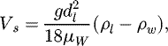 (1)where dl, μw
, ρl
and ρw
are the average lees diameter, the dynamic viscosity of wine, the densities of lees and wine, respectively. The temperature dependence of champagne wine density is given by [7]:
(1)where dl, μw
, ρl
and ρw
are the average lees diameter, the dynamic viscosity of wine, the densities of lees and wine, respectively. The temperature dependence of champagne wine density is given by [7]: (2)
(2)
Besides, the temperature dependence of the dynamic liquid viscosity accurately follows an Arrhenius-like equation [8]: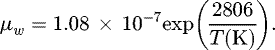 (3)
(3)
For light lees with a 5 μm diameter and a wine temperature of 12 °C, the sedimentation velocity is calculated to be 0.0016 mm s−1. The question now arises as to how the sedimentation rates of the light lees, originated by gravity, interact with the vortex velocities of the flow, the intensities of which are variable. A PIV measurement system including a Litron Nd:YAG laser and a CCD camera for acquisition [9] make it possible to measure the velocity intensities in the wine container. The maximum recorded velocities are about 1.2 mm s−1, 1000 times higher than the sedimentation velocities. It can thus be suggested that the sedimentation rate of the particles, by itself, is not a parameter likely to influence the resuspension of light lees.
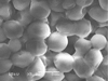 |
Fig. 1 Electron microscope images of light lees (magnification ×5000). |
2.2 Flow dynamics and resuspension of light lees
To highlight the natural convection flow behavior, a first experiment was conducted using clear white wine at 12 °C, in the absence of lees. The sample was subjected to a low positive temperature gradient (external environment temperature at 15 °C, slightly higher than wine). Because of the axisymmetric structure of the convective flow, a 2D investigation is sufficient to correctly unveil the dynamics of the whole 3D flow. Thus, by means of a 2D2C PIV laser process in the axial plane, the natural convection flow can be visualized [10]. To achieve this, the fluid is seeded with neutrally buoyant glass-hallow spheres (9–13 μm; 1.1 g cm−3) which generate sufficient light scattering and excellent traceability of the flow. The flow analysis in Figure 2 displays a behavior correlated to the sign of the low thermal gradient imposed [7,11,12]. A positive thermal gradient induces upward vertical motion of the fluid along the receptacle wall. The axisymmetric container then generates large-scale counter-rotating vortex cells whose core is close to the vertical side wall. The size of this annular vortex then induces a movement of almost all the fluid in the container by viscous friction. It is clearly observed that the smallest flow velocities are found in the lower part of the container, where the deposit of light lees is concentrated.
While Figure 2 perfectly illustrates the fact that natural convection is the driving force behind the movement of wine in the container, particular attention must be paid to what occurs in the lower part of the receptacle and more specifically at the interface between the flow and the bottom wall. Indeed, the interaction taking place at this location will initiate the movement of light lees and the further process of their resuspension within the container. Figure 2 also shows the schematization of the surface flow at the bottom of the container. It is worth noting that a positive thermal gradient at the wall will generate a parietal radial flow from the center of the container to the side wall of the container.
To highlight the lees in motion, a laser tomography process (0.8 W argon laser light sheet − INNOVA 70Ce2W) was used to visualize the resuspension of the lees. In this case, unlike the visualization of lees-free flow structure where tracers had been added, the lees play that role and their resuspension is clearly visible in Figure 2. The flow being axisymmetric, only half of the receptacle is represented and compared to the analysis of the flow dynamics of the liquid alone. The most striking observation is that the resuspension of the lees accurately follows the general structure of the natural convection flow. If the thermal gradient is positive, the lees from the bottom of the container are directed upward near the wall to form a main vortex. This proves that low thermal gradients induce a mixing process whose energy is sufficient to resuspend part of the lees deposit. Nevertheless, it seems that unlike mechanical stirring such as “bâtonnage”, the energy of the flow for low thermal gradients does not allow all the sedimented lees to be stirred. However, we can legitimately think that higher thermal amplitudes will result in greater mixing intensities.
 |
Fig. 2 Resuspension process of light lees under low positive thermal gradient T hot − T cold = +3 ° C: streamline pattern from PIV and corresponding lees in motion (left), topological behavior at the bottom of the receptacle (right), 15 min after the start of the room heating process. |
3 Winery tank shapes
Four wine tank geometries have been studied. The cylindrical stainless steel tank is considered as the wine industry standard design. Derived from cylindrical shapes, truncated conical or even double truncated conical shapes, most often made of stainless steel, have appeared in recent years in wineries. Finally, one of the latest trends in winemaking equipment involves egg-shaped wine tanks.
No scientific study in literature compares the wine tanks and offers guidance in the choice of a wine mixing methodology other than mechanical for winegrowers. Selecting criteria for commercial wine storage tanks comparison purposes, from the viewpoint of natural thermal convection driven wine mixing, is a delicate issue. The tanks can actually display radically different geometries, capacities and materials (e.g. stainless steel, plastic, concrete, sandstone, etc.).
The present study deliberately focuses only on the tank geometry: discarding the influence of thickness and type of manufacturing material makes it possible to circumvent the related thermal inertia.
However, in order to increase relevance of this geometric comparison, the following three assumptions have been made in all studied cases:
-
thermal gradient between the external environment of the cellar and the stored wine is identical, leading to the same Grashof number (thermal similarity parameter) related to the heated height;
-
thickness (5 mm) and material (stainless steel) are identical, which allows discarding thermal inertia concerns;
-
tank dimensions are selected such that the ratio of height H to maximum width L equals 2, as shown in Figure 3.
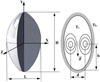 |
Fig. 3 Coordinates system (left) and uniform wall temperature (UWT) conditions (right). |
4 Numerical approach
For a 3D geometry in cylindrical coordinates, the governing equations are as follows:
Continuity equation: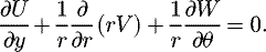 (4)
(4)
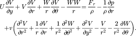
Navier-Stokes equations: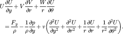 (5)
(5)
 (6)
(6)
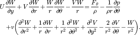 (7)
(7)
Energy equation (with P = 0)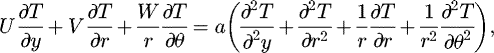 (8)where U, V, W, are the three components of velocity in the y (vertical), radial and orthoradial directions respectively, p is the static pressure, F
y, F
r and F
θ
are the volume forces (gravity, downward force), v is the kinematic viscosity of the fluid and T is the temperature.
(8)where U, V, W, are the three components of velocity in the y (vertical), radial and orthoradial directions respectively, p is the static pressure, F
y, F
r and F
θ
are the volume forces (gravity, downward force), v is the kinematic viscosity of the fluid and T is the temperature.
From a physical viewpoint, winery tanks may be considered as finite spaces bounded by walls in which internal natural convection can occur as soon as a temperature differential exists between the wine and the external environment. Internal natural convection is different from the cases of external convection, where a heated or cooled wall is in contact with quiescent fluid and the boundary layer development is not restrained. Internal convection cannot be treated using simple boundary layer theory, since the entire fluid within the tank is involved in the convection motion. Consequently, only a numerical approach can solve this problem of internal natural convection.
The calculation domain was meshed using ANSYS Workbench Meshing® software. The three-dimensional mesh consists in about 750 000 cells, mainly composed of hexahedral elements, as seen in Figure 4. It must be noted however that the mesh size can slightly vary from one tank geometry to another.
The Cartesian grid is refined in the vicinity of the wall, where high resolution is required to accurately compute the boundary layer. Conversely, for computation cost purposes, far field computations may be carried out based on a coarser mesh. The problem of interest is therefore three dimensional and temperature dependent. ANSYS Fluent 18.2® commercial code was used to calculate the anisothermal flow in the 3D calculation domain. Due to the temperature difference between the wine (12 °C) and the environment (20 °C), the flow near the wall of the tank is considered as a free-convection flow.
Convective exchanges require the activation of the energy equation to take thermal transfer phenomena into account. The choice of the k − ϵ turbulence model is based on the analysis of Reynolds and Rayleigh numbers, both of them demonstrating that the flow regime is fully turbulent. To solve the problem, initial and boundary conditions are defined as follows: a constant temperature is applied to the tank walls as well as a no-slip condition. To initialize the calculation, fluid flow velocity components is set to be zero (U = V = W = 0).
CFD calculation is stopped when a thermal equilibrium between wall temperature and fluid is reached. The SIMPLE algorithm was preferred to solve the pressure–velocity coupling, using a first order discretization scheme. Moreover, an adaptive time step ensures faster convergence of the results.
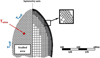 |
Fig. 4 Meshing of the fluid domain and detail of the mesh refinement in the vicinity of the wall. |
5 Results
This section describes the “pure” hydrodynamic results only, i.e. the fluid dynamics in the absence of particles, although the achieved results can be considered as sufficient to compare the different tanks designs for industrial winery applications. The computed streamline patterns are presented in Figures 5 and 6.
At the beginning of the heating process, the quasi-totality of the heat flux from the warm wall is used to accelerate the liquid in the adjacent viscous layer. The initially dominant conductive heating is gradually replaced by convection.
Common to all tank shapes is that through the heating process, the wine along the walls of the tank becomes slightly warmer and rises upwards. Each tank being a confined space, the upward flow on the side walls is blocked at the top of the tank and forced to descend along the vertical axis of symmetry. These two stages of fluid flow give rise to an overall vortex behavior. The motion, generated by the temperature differential, ensures ongoing and gentle mixing of the two main areas of the tank, in the form of an annular fluid movement which is observed in each tank geometry.
Remarkable topology discrepancies may be noted, mostly from Figure 6. Three distinct situations occur depending on the presence of a single, double or triple vortex ring (VR). The two geometries in which a single VR develops are the double-truncated and egg-shaped ones. The upward divergent conical tank displays, beside the main vortex ring, a counter-rotating one in the upper part. Finally, in the cylindrical tank, two VR initiations are observed in the lower and upper part.
In addition, a junction of the side and upper or lower walls forming an angle below or equal to 90° is likely to initiate secondary VRs (cylindrical and upper part of the conical tank). Conversely, a larger angle prevents the VR from developing (lower part of the conical tank, upper and lower part of the double-truncated tank). The presence of these secondary VRs undoubtedly plays a role in the homogenization of macromixing, but one may also infer that part of the fluid remains confined within, thus participating to a lesser extent in the exchanges of organoleptic compounds.
The kinetic energy of wine in motion is influenced by pressure drops caused by tank shells with curved or sharp-edged corners. The point is to assess the influence of the tank shapes in the mixing process, in terms of intensity of the vortices and maximum velocities. Indeed, the greater the vorticity and velocities within the tank, the more efficient the passive stirring and resuspension of the lees. Figure 7 and Table 1 summarize the velocity and vorticity parameters calculated for the four wine tank shapes. Similar behavior of the velocity profile is observed, regardless of the tank geometry (Fig. 7a). The thickness of the dynamic boundary layer initiating along the side walls seems to be independent of the tank geometry as well. The maximum velocities in this upward boundary layer are reached in descending order as follows: egg-shaped, cylindrical, conical and double-truncated geometry. One remarkable result is that these velocities are 60 to 450 higher than the sedimentation speed of light lees previously calculated.
Regarding the evolution of the longitudinal velocity as a function of the vertical coordinate within the tanks, it is first clearly observed that maximum values are reached at the vortex ring core, and that the presence or not of secondary VRs is denoted by a change of sign.
These curves also prove that an egg-shaped tank provides the highest speeds and vorticities. Vorticity, which may be thought of as the mixing intensity, is found to be twice as high for this geometry than for all others (gain ranging from 104 to 112%). Likewise, maximum velocities are higher for this type of tank (gain between 19 and 47%). On the other hand, tanks, such as the cylindrical one, featuring sudden changes in the main flow direction induce the lowest maximum speeds and vorticity. The egg-shaped tank is free from corners prone to baffle and disturb the motion: its special shape results in the lees being continuously raised by an internal current resembling a vortex.
As mentioned earlier, all tanks have equal height H and maximum width L, such that ratio  . In these conditions, parameters d/L and h/H stand for the horizontal and vertical spatial locations of the main vortex ring cells (see Fig. 3). These data are important as they correspond to the position of the mixing source, and the role played by the tank geometry in this spatial distribution cannot be emphasized too much.
With regard to the relative height of the main VR, no difference is highlighted between the cylindrical and egg-shaped geometries: it is located half-way up in both cases ( For the double-truncated geometry, the location of the VR core is conditioned by the intersection of the two generatrix sets. Finally, in the upward diverging single truncated tank, the mixing source is located in the upper part, where the largest space is available for it to develop (
 ).
).
No significant discrepancy is observed in the sizes of the main VR, characterized by ratio d/L, for the cylindrical, double-truncated and egg-shaped geometries. In these cases, the vortex cores are found in the vicinity of the walls, while they lie closer to each other ( in the conical geometry. We can reasonably conclude that both the cylindrical and egg-shaped tanks are the configurations offering the most homogeneous mixing of the whole volume.
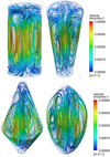 |
Fig. 5 Color-coded velocity visualization of 3D streamline patterns. |
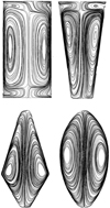 |
Fig. 6 Streamlines in a YZ plane. |
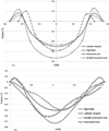 |
Fig. 7 Velocity profiles along the horizontal axis joining the vortex cores (a) and along the axis of symmetry of the tank (b). |
Velocity and geometrical parameters related to vortex behavior for all four tank shapes.
6 Design of a helical corrugated tank: a way to enhance mixing in winery?
One possible further application of the numerical studies presented in this paper is to improve mixing by using passive methods such as a helical corrugated inner wall, in effort to generate swirling counter-flow. Numerous engineering applications implement swirling counter-flows, such as combustion, heat exchangers, cyclonic separation and mixing. The specific design of such systems creates swirls in the previously straight streamlines, giving rise to two different flows. One is located in the vicinity of the longitudinal axis of the tank and descends parallel to it, while the other concerns the ascending, near-wall fluid layers and has a circular motion about the revolution axis [13,14].
As seen in Figure 8, fluid motion inside the tank follows an overall spiraling path, resulting in a longer effective mixing length compared to a regular cylindrical tank.
The benefit of this particular design compared to a common, smooth one is that it prevents secondary vortex rings from developing at the bottom of the tank, which most probably ensures resuspension of lees that would naturally form a deposit. However, a VR is still observed in the upper part of the tank.
Optimization studies aimed at enhancing mixing and preventing lees from accumulating remain to be performed in terms of geometric parameters of the swirling counter-flow coil or inner wall: width, helix angle, slope, etc.
This transition from an annular vortex flow situation (smooth wall) to a bidirectional vortex flow (helical corrugated wall) seems to be a possibility to be explored in future research.
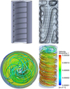 |
Fig. 8 Flow behavior inside a helical corrugated tank. |
7 Limitations
For computational cost purposes, all numerical simulations were carried out under the assumption of three-dimensional steady state ( ). All results are related to an achieved thermal state of equilibrium within the tanks and are correlated to the thermal inertia of the system. A more thorough analysis should take the unsteady character of the flow into account, which would allow for proper comparison of all tank geometries at the exact same time. Although such aspects were discarded in the present work, the obtained results make it possible to compare the dynamic fields responsible for macromixing and consequently, resuspension of light lees.
8 Conclusion
In this study, numerical simulations pertaining to natural convection in winery tanks have been presented. To the best of the author's knowledge, it constitutes a pioneering work in the understanding of the mechanisms governing the resuspension of wine light lees when mixing is of thermal origin rather than mechanical (e.g. by “bâtonnage”).
First, it has been shown from PIV measurements that even low thermal gradients between the external environment (wine cellar) and the wine stored in tanks suffice to generate motion of the entire wine volume. Then, laser tomography experiments have confirmed that the associated low speed movements are sufficient to detach the lees from the bottom of the vats and resuspend them, thus improving the quality of the wines during their ageing. From a CFD study on four different types of commercial wine tanks, the influence of geometry on the spatial distribution of annular vortex flow has been demonstrated, as well as on flow velocities. Innovative curved geometries such as the egg-shaped, in the absence of sharp-angled walls, result in higher flow velocities and, by extension in improved wine mixing. Finally, a comparative study on the use of non-smooth inner tank walls was initiated. Indeed, it seems that the addition of coils on the inner wall of the tank is likely to increase the mixing, even if the tangential speeds at the bottom of the tank (where the lees have sedimented) are lower.
Acknowledgments
The authors wish to thank the EXPERI platform for its technical help and the Communauté d'Agglomération de Châlons en Champagne for its financial support.
References
- G. Fia, B. Zanoni, C. Gori, A new technique for exploitation of wine lees, Agric. Agric. Sci. Procedia 8, 748–754 (2016) [Google Scholar]
- S. Perez-Magarino, M. Ortega-Heras, M. Bueno-Herrera, L. Martínez-Lapuente, Z. Guadalupe, B. Ayestaran, Grape variety aging on lees and aging in bottle after disgorging influence on volatile composition and foamability of sparkling wines, LWT 61, 47–55 (2015) [CrossRef] [Google Scholar]
- J.A. Pérez-Serradilla, M.D. Luque de Castro, Role of lees in wine production: a review, Food Chem. 111, 447–456 (2008) [Google Scholar]
- S. Colombié, S. Malherbe, J.M. Sablayrolles, Modeling of heat transfer in tanks during wine-making fermentation, Food Control 18, 953–960 (2016) [Google Scholar]
- S. Kakaç, Y. Yener, Convective heat transfer, 2nd edn. CRC Press, Boca Raton (1995) [Google Scholar]
- J. Lachman, K. Rutkowski, P. Travnicek, T. Vitez, P. Burg, J. Turan, P. Junga, V. Visacki, Determination of rheological behaviour of wine lees, Int. Agrophys. 29, 307–311 (2015) [Google Scholar]
- P. Hlavac, M. Bozikova, Z. Hlavacova, K. Kardjilova, Changes in selected wine physical properties during the short-time storage, Res. Agric. Eng. 62, 147–153 (2016) [CrossRef] [Google Scholar]
- G. Liger-Belair, M. Parmentier, P. Jeandet, Modeling the kinetics of bubble nucleation in champagne and carbonated beverages, J. Phys. Chem. B 110, 21145–21151 (2006) [CrossRef] [PubMed] [Google Scholar]
- F. Beaumont, G. Liger-Belair, G. Polidori, Flow analysis from PIV in engraved champagne tasting glasses: flute versus coupe, Exp. Fluids 56, 170 (2015) [Google Scholar]
- F. Beaumont, G. Liger-Belair, G. Polidori, Unveiling self-organized two-dimensional (2D) convective cells in champagne glasses, J. Food Eng. 188, 58–65 (2016) [Google Scholar]
- A. Rodrigues, L.M. Ricardo-Dasilva, C. Lucas, O. Laureano, Characterization of annoproteins during white wine ageing on lees with stirring in oak wood barrels and in a stainless-steel tank with oak staves, J. Int. Sci. Vigne Vin 46, 321–329 (2012) [Google Scholar]
- J. Correia, A. Mourão, M. Cavique, Energy evaluation at a winery: a case study at a Portuguese producer, MATEC Web Conf. 112, 10001 (2017) [CrossRef] [Google Scholar]
- T. Kumaresan, S. Thakre, Characterization of flow mixing and particle suspension in alumina draft tube precipitators of taller aspect ratio, Hydrometallurgy 150, 107–122 (2014) [CrossRef] [Google Scholar]
- T. Perarasu, M. Arivazhagan, P. Sivashanmugam, Experimental and CFD heat transfer studies of Al2O3-water nanofluid in a coiled agitated vessel equipped with propeller, Chin. J. Chem. Eng. 21, 1232–1243 (2013) [CrossRef] [Google Scholar]
Cite this article as: F. Bogard, F. Beaumont, Y. Vasserot, S. Murer, F. Simescu-Lazar, G. Polidori, Passive wine macromixing from 3D natural convection for different winery tank shapes: application to lees resuspension, Mechanics & Industry 21, 207 (2020)
All Tables
Velocity and geometrical parameters related to vortex behavior for all four tank shapes.
All Figures
|
Fig. 1 Electron microscope images of light lees (magnification ×5000). |
| In the text | |
|
Fig. 2 Resuspension process of light lees under low positive thermal gradient T hot − T cold = +3 ° C: streamline pattern from PIV and corresponding lees in motion (left), topological behavior at the bottom of the receptacle (right), 15 min after the start of the room heating process. |
| In the text | |
|
Fig. 3 Coordinates system (left) and uniform wall temperature (UWT) conditions (right). |
| In the text | |
|
Fig. 4 Meshing of the fluid domain and detail of the mesh refinement in the vicinity of the wall. |
| In the text | |
|
Fig. 5 Color-coded velocity visualization of 3D streamline patterns. |
| In the text | |
|
Fig. 6 Streamlines in a YZ plane. |
| In the text | |
|
Fig. 7 Velocity profiles along the horizontal axis joining the vortex cores (a) and along the axis of symmetry of the tank (b). |
| In the text | |
|
Fig. 8 Flow behavior inside a helical corrugated tank. |
| In the text | |
Current usage metrics show cumulative count of Article Views (full-text article views including HTML views, PDF and ePub downloads, according to the available data) and Abstracts Views on Vision4Press platform.
Data correspond to usage on the plateform after 2015. The current usage metrics is available 48-96 hours after online publication and is updated daily on week days.
Initial download of the metrics may take a while.