| Issue |
Mechanics & Industry
Volume 21, Number 6, 2020
|
|
|---|---|---|
| Article Number | 611 | |
| Number of page(s) | 8 | |
| DOI | https://doi.org/10.1051/meca/2020081 | |
| Published online | 19 November 2020 | |
Regular Article
Investigation of sliding mode control for nonlinear suspension systems with state estimation
1
School of Mechatronics & Vehicle Engineer, Chongqing Jiaotong University, Chongqing 400074, China
2
State Key Laboratory of Fluid Power and Mechatronic Systems, Hangzhou 310027, China
3
School of Intelligent Manufacturing Engineering, Chongqing University of Arts and Sciences, Chongqing
402160, China
* e-mail: bit_cx@163.com
Received:
26
July
2019
Accepted:
1
October
2020
This paper presented a new control strategy for active suspension of nonlinear quarter-vehicle model. An active suspension controller designed for using sliding mode control with noise filtering. The Kalman filter (KF) predicted the state response of the nonlinear one-quarter automobile model, and the estimated values used for the design of the active control force. Finally, the shock absorption performance compared with the LQR controller and the passive suspension. The simulation results showed that the control method significantly improve the ride performance and safety of the vehicle.
Key words: Active suspension control / sliding mode control / non-linear model / Kalman filter
© AFM, EDP Sciences 2020
1 Introduction
The riding comfort and road handling capabilities depend on the performance of the suspension system. However, there is a contradiction between the ride comfort and the road holding in vehicle suspension systems. The traditional passive suspension is painful to get the optimal control effect on this problem. To solve this problem, the researchers proposed semi-active suspension [1] and active suspensions [2]. Whereas, the active suspension is better than semi-active suspension for improved ride comfort due to structural constraints. Therefore, the design of active suspensions is a hot spot in modern vehicle control research.
Various control methods have proposed to achieve active control of the suspension. Sun et al [3] discussed the problem of H∞ control for vehicle active suspension systems in the finite frequency domain. The results showed that the ride comfort had improved, and the time-domain constraints guaranteed by linear matrix inequality optimization. Jamil et al [4] studied the optimal problem of actuator output force in suspension, combining optimal control with intelligent control technology. The suspension system has a high damping characteristic of LQR control. The actuator produces moderate peak and stable amplitude control force to improve the ride quality and handle stability of to automobile and comfort of passengers. Wang et al [5] used the vehicle body acceleration as to the control target and optimized the control rules with the improved Fuzzy-PID control strategy to speed up the optimization. The experimental results have achieved good global optimization performance. Their test results showed that it can suppress the vertical acceleration of the car body significantly and improves the driving comfort. Based on the multi-performance target optimization algorithm, Crews et al [6] considered the performance objectives of ride comfort and damping power dissipation and used the multi-objective genetic algorithm (MOGA) to determine the optimal performance of the controller. The results show that the two performance goals improved. By those control methods, we know that researchers have considered different optimization goals to achieve the requirements of active control. However, they all assume the vehicle model as a linear structure.
The nonlinear problem of the spring rigidity and damping of the suspension were not considered. Actually, the vehicle suspension is a nonlinear system, operating conditions are also changing, and there is always noise interference during the operation of the vehicle and the signal acquisition of the sensor [7]. The measurement of the state variable of the suspension is still incomplete in the actual procedure. These have limitations on the design of the controller. Therefore, if we only consider the linear vehicle model when designing the controller, the control effect is not satisfactory in practical engineering applications.
This paper uses the variable structure control method to solve the nonlinear problem of the system. Because the sliding mode control structure is easy to design, and if the conditions met, the system is entirely adaptive to the system interference and parameter perturbation, and the system has strong robustness [8–10]. The state of the system is required to design the sliding mode controller, and the acquired state signal uses the Kalman filter to remove the noise to get the actual value. The proportional integral PI method is used to the sliding surface, which provides greater freedom and reduces stability error. The simulation results demonstrate the effectiveness and robust of the proposed active suspension control method.
2 Quarter-car model
In the previous classic suspension model, springs and damping were often seem as linear components, simplifying the study. However, this does not adequately describe the real car suspension; the effect is limited when applied to the actual suspension. This paper considers the inherent nonlinearity and parameter uncertainty of the vehicle suspension system [11].
The design of the filter and control mechanism requires a dynamic equation for the suspension. This paper applies the classic quarter suspension model shown in Figure 1, where ms represents the mass of the car body and mu represents the mass of the tire system. The suspension and shock absorbers that connect the body, and the tire have stiffness and damping coefficients of ks and bs, while the rubber tires are approximated as elastic members with the stiffness of Kt. In the model, zs represents the displacement of the vehicle body, zu is the displacement of the tire, and zr is the input excitation of the road surface. The variable force u represents the force at which the controller generates active control.
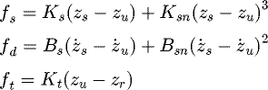
According to Newton's second law, the force equations of the model are
Where the damping force and spring force of the suspension in the formula take into account its nonlinear characteristics, and the simplified tire force, respectively, are as follows
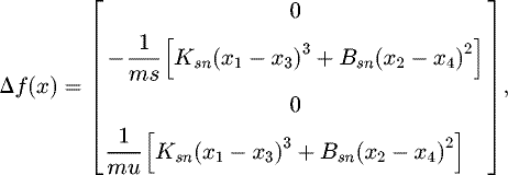
Here, the nonlinear damping coefficient bs is composed of Bs and Bsn , Bs describes the linear part of the damper, and Bsn represents the performance of the nonlinear part of the damper. The nonlinear stiffness Ks of the suspension is obtained by combining the linear coefficient portion Ks and the nonlinear coefficient portion Ksn .
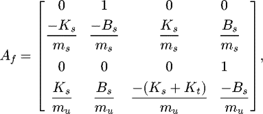
Substituting the state vector  into the formula (1) (2) yields a simple nonlinear state equation as follows
Where d(x, t) =Δf(x) + Ezr ,
Where d(x, t) contains nonlinear and uncertain structures in the suspension system.
Assumption: There is a known β∊R+ such that ||d(x, t) ||≤β, where || · || represents the spectral norm of the vector or matrix.
 |
Fig. 1 Quarter-car model. |
3 Sliding surface and controller design
Because of the nonlinearity of the vehicle model and the disturbance of the road, the riding comfort and road handing of the vehicle depends on the performance of the suspension system. This paper applies the sliding mode control method to design the active control force. Firstly, the sliding surface needs to be designed to ensure that the system motion track slides along the specified line to the equilibrium point. In our paper, we use the proportional integral sliding surface expression as follows: (4)
(4)
Where C∊ℝ
m×n
and E∊ℝ
n×n
are constant matrices, to get the system into the sliding mode, you must ensure that s = 0 is established. At the same time, the equivalent control force ueq
(t) is obtained from  [12]
[12]
If there is a matrix C such that CB is a non-singular matrix, the equivalent control force ueq
is (6)
(6)
Substituting Equation (6) into the system (3), the feedback closed-loop system dynamics equation is as follows (7)
(7)
Theorem. If  , the system (7) is bounded and stable on the sliding surface s=0.
Proof. In order to simplify the certification process, we let (7a)
(7a)
 (7b)
(7b)
Then Equation (7) is simplified to (8)
(8)
We choose the following Lyapunov function related to the vector x(t). (9)
(9)
Deriving V(t) along the trajectory of x(t), gives (10)
(10)
Where Q is an arbitrary positive definite symmetric matrix, then P is the unique solution corresponding to equation  . Equation (10) can be rewritten as
 (11)
(11)
It is known that λmin
(Q)>0, the  is satisfied for all x(t) satisfying
  .
.
Therefore, the suspension system is bounded stability.
In this paper, the constant reaching law is used, and the saturation function is used to weaken the chattering. Finally, the control law of the uncertain system is obtained. (12)
(12)
 (13)
(13)
Thus,  . By comparing Equation (5), (12) and (14), the hitting condition is satisfied.
4 Kalman filter
The sensor measures the state quantity of the suspension. Nevertheless, due to the actual constraints, only certain state variables can be tested, and there is noise in the process of signal acquisition. Therefore, the Kalman filter is used to filter out the noises, and all state variables are estimated [13]. Finally, the controller is designed based on state estimates.
In order to meet the design conditions of the Kalman filter, we can rewrite the system Equation (3) as: (15)
(15)
Where G = [B, E ] and  . Af
(x) is a time-varying matrix, which can vary according to changes in the state of the system. In general, the relative displacement zs
-zu
and the relative speed
  between the body and the tire can be measured by sensors. Converting a continuous state equation to a discrete state equation by a zero-order keeper is shown below.
 (16)
(16)
 (17)
With
  . Where k is the kth
sample data, Φ(x(k−1),k−1), Γu and Γw represent the system parameter matrix, control input matrix and external interference matrix of the discrete state equation, respectively. H is the output matrix, and w and v represent the process noise vector in the suspension operation and the noise vector in the sensor measurement, respectively. Then we can obtain the Kalman filter as follows:
 (18)
(18)
 (19)Where
  and
and  are the estimated state and output vectors, respectively.
Here. P(k|k) is the estimation error variance matrix, and K(k) represents the Kalman gain; Where R = E [v(k)vT
(k)] and Q = E [w(k)wT
(k)] represent the covariance matrices of noises w and v, respectively. After using the estimated state vector  obtained by the filtering, the actual output control force u is calculated as follows
 (21).
(21).
In the actual damping system, it is required to decouple the control from the external disturbance, since the external disturbance zr
is challenging to detect and estimate online. When (CB)−1
CE = 0, the requirement is satisfied. Finally, the control power is reduced to
 (22).
(22).
5 Performance measures
Due to the limited space between the car body and the tire, its size must not exceed the maximum value xr
. This article uses relative suspension deflection (RSD) to evaluate whether the suspension interferes with the body, denoted by ζ, is defined as (23)
(23)
To ensure that the wheels do not leave the ground, use the relative tire force (RTF) to show whether the dynamic load of the tire exceeds the static tire load, denoted by φ, is defined as (24)
(24)
Both RSD and RTF values must be guaranteed to be less than 1, so that the car can travel smoothly and safely. The vertical acceleration  of the vehicle measures the comfort of the ride.
6 Simulation and discussion
For reflecting the performance of the control method proposed in this paper, we compare it with the linear quadratic regulator (LQR) control approach and passive suspension. Vehicle model parameters are shown in Table 1, and the initial value of the state vector x is set to x(0) =[0000] T.
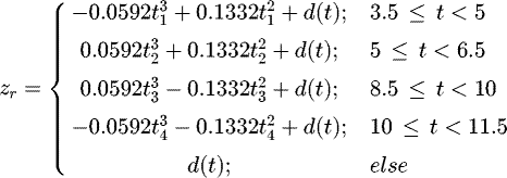
The road input disturbance is given by (25)
(25)
Where d(t) = 0.002sin(2πt) + 0.002sin(7.5πt) is a periodic disturbance and the time intervals are described as t1 = t − 3.5, t2 = t − 6.5, t3 = t − 8.5 and t4 = t − 11.5. This road input excitation was applied in Chen [14] and Pusadkar [15] research.
The parameters of the LQR controller are as follows: the objective performance functions considered in this article include  , zs − zu
, zu − zr
and u. The weighting matrices Q and R are selected as Q = diag[ q1, q1, q3] where q1 = 20, q2 = q3 = 1 × 10⁴ , and R = 1 × 10⁻⁴ . The Riccati algebraic equation is solved according to the parameters of the suspension system at different times, and the optimal feedback gain at each moment is obtained. The structural parameters of the sliding mode control during simulation are selected as C = [−300, 300, 1000, 0], E = diag[ 20, 5, 11, −5], k = 1 and δ = 0.001.
In the case of road input and noise interference, the suspension system uses a Kalman filter to estimate the suspension state vector when the sensor number is limited.
Figures 2a–d show simulated results of estimated suspension displacement, spring mass velocity, tire displacement and unsprung mass velocity. The error between the estimated value and the actual cost is shown in Table 2. It can be seen that the unsprung mass displacement error RMS is greater than the sprung mass displacement error, and the velocity error RMS difference between the two is small. The results show that the estimated value after filtering within the allowable range of error can adequately describe the real state of the suspension.
To verify the performance of the proposed PISMC control method, the LQR control strategy and passive suspension are used as reference objects. The results are shown in Table 3. Figure 3 is responses of suspension displacement. As can be seen that PISMC can more effectively restrain the displacement of the sprung mass. The acceleration of sprung mass  is shown in Figure 4. Compared with passive suspension, the vertical acceleration of the car body is reduced by about 27.8%, and the LQR control method is increased. Figures 5 and 6 show the results of RSD and RSF, respectively. The relative suspension deflection has increased a lot due to the characteristics of active control. This increase is acceptable within the allowable space. In terms of operational stability, the PISMC method is similar to passive suspension, and the LQR method is superior.
Parameter values of the quarter suspension model
 |
Fig. 2 Estimation results of Kalman filter. |
 |
Fig. 3 Responses of suspension displacement. |
Summary of estimation error results of Kalman filter
Simulation results of performance parameters
 |
Fig. 4 Responses of suspension acceleration. |
 |
Fig. 5 Relative suspension deflection. |
 |
Fig. 6 Relative tire force. |
7 Discussion
This paper proposes sliding mode active control based on signal filtering and considers the nonlinearity of the suspension system and the influence of external uncertain disturbances. The PISMC control strategy was adopted for improve the robustness of the system to parameter changes and external disturbances. Besides, to achieve better control effect, more system state variables of the system needed for the control force. Due to practical engineering constraints, the sensor can only collect a part of the state signal, and the suspension system is running with a lot of noise in the acquisition signal engineering. In order to avoid adverse effects on the control system, the state of the suspension estimated by a Kalman filter to meet the design requirements.
The results show that the filtered estimate is consistent with the real value, enabling the controller to perform accurate control. In terms of control effect, compared with the performance of LQR and passive suspension, PIMSC has dramatically reduced the displacement and acceleration of the vehicle body, which can significantly improve the ride comfort and at the same time.
Funding
This research was funded by the subproject of the National Key Research and Development Program of China (No. 2018YFB2001400), National Natural Science Foundation of China (51705051); Basic Natural Science and Frontier Technology Research Program (ccstc2017jcyjAX0169); China Postdoctoral Science Foundation (2018M643420 and 2019T120813); Open Foundation of the State Key Laboratory of Fluid Power and Mechatronic Systems (GZKF-201808). Open Foundation of the State Key Laboratory of Mechanical Transmission (SKLMT-KFKT-201804).
Conflicts of Interest
The authors declare no conflict of interest.
Author contribution statement
Conceptualization, X.C. and S.H.; data curation, S.H.; formal analysis, X.C. and S.H.; funding acquisition, X.C. and T. L.; investigation, X.C. and S.H.; methodology, S.H.; project administration, X.C.; resources, D.G.; software, S.H.; supervision, X.C.; validation, S.H.; visualization, S.H.; writing—original draft preparation, S.H.; writing—review and editing, S.H., X.C. and T.L.
References
- M. Canale, M. Milanese, C. Novara, Semi-active suspension control using “fast” model-predictive techniques. IEEE Transactions on Control Systems Technology 14 , 1034–1046 (2006) [CrossRef] [Google Scholar]
- J. Cao, H. Liu, P. Li, State of the art in vehicle active suspension adaptive control systems based on intelligent methodologies. IEEE Transactions on Intelligent Transportation Systems 9 , 392–405 (2008) [CrossRef] [Google Scholar]
- W. Sun, H. Gao, O. Kaynak, Finite frequency, control for vehicle active suspension systems. Control Systems Technology IEEE Transactions on 19 , 416–422 (2011) [CrossRef] [Google Scholar]
- M. Jamil, A.A. Janjua, I. Rafique, Optimal control based intelligent controller for active suspension system. Life Science Journal 10 , 653–659 (2013) [Google Scholar]
- W. Wang, Y. Song, Y. Xue, An optimal vibration control strategy for a vehicle's active suspension based on improved cultural algorithm. Applied Soft Computing 28 , 167–174 (2015) [Google Scholar]
- J.H. Crews, M.G. Mattson, G.D. Buckner, Multi-objective control optimization for semi-active vehicle suspensions. Journal of sound and Vibration 330 , 5502–5516 (2011) [Google Scholar]
- Y. Qin, Z. Wang, C. Xiang, Speed independent road classification strategy based on vehicle response. Theory and experimental validation. Mechanical Systems and Signal Processing 117 , 653–666 (2019) [Google Scholar]
- J. Yang, S. Li, X. Yu, Sliding-mode control for systems with mismatched uncertainties via a disturbance observer. IEEE Transactions on industrial electronics 60 , 160–169 (2013) [CrossRef] [Google Scholar]
- F. Plestan, Y. Shtessel, V. Bregeault, New methodologies for adaptive sliding mode control. International journal of control 83 , 1907–1919 (2010) [Google Scholar]
- X. Chen, S. Han, J. Li et al., Chaos suppression for coupled electromechanical torsional vibrations in a high-speed permanent magnet synchronous motor driven system via multitime delayed feedback control. International Journal of Bifurcation and Chaos 30 , 1–13 (2020) [Google Scholar]
- C. Kim, P.I. Ro, A sliding mode controller for vehicle active suspension systems with non-linearities. Proceedings of the Institution of Mechanical Engineers, Part D: Journal of Automobile Engineering, 212 , 79–92 (1998) [CrossRef] [Google Scholar]
- P. Hušek, Adaptive sliding mode control with moving sliding surface. Applied Soft Computing 42 , 178–183 (2016) [Google Scholar]
- Z. Wang, M. Dong, Y. Qin, Suspension system state estimation using adaptive Kalman filtering based on road classification. Vehicle System Dynamics 55 , 371–398 (2017) [CrossRef] [Google Scholar]
- P.C. Chen, A.C. Huang, Adaptive sliding control of non-autonomous active suspension systems with time-varying loadings. Journal of Sound and Vibration 282 , 1119–1135 (2005) [Google Scholar]
- U.S. Pusadkar, S.D. Chaudhari, P.D. Shendge, Linear disturbance observer based sliding mode control for active suspension systems with non-ideal actuator. Journal of Sound and Vibration 442 , 428–444 (2019) [Google Scholar]
Cite this article as: X. Chen, S. Han, T. Luo, D. Guo, Investigation of sliding mode control for nonlinear suspension systems with state estimation, Mechanics & Industry 21, 611 (2020)
All Tables
All Figures
 |
Fig. 1 Quarter-car model. |
| In the text | |
 |
Fig. 2 Estimation results of Kalman filter. |
| In the text | |
 |
Fig. 3 Responses of suspension displacement. |
| In the text | |
 |
Fig. 4 Responses of suspension acceleration. |
| In the text | |
 |
Fig. 5 Relative suspension deflection. |
| In the text | |
 |
Fig. 6 Relative tire force. |
| In the text | |
Current usage metrics show cumulative count of Article Views (full-text article views including HTML views, PDF and ePub downloads, according to the available data) and Abstracts Views on Vision4Press platform.
Data correspond to usage on the plateform after 2015. The current usage metrics is available 48-96 hours after online publication and is updated daily on week days.
Initial download of the metrics may take a while.


