| Issue |
Mechanics & Industry
Volume 21, Number 4, 2020
|
|
|---|---|---|
| Article Number | 412 | |
| Number of page(s) | 12 | |
| DOI | https://doi.org/10.1051/meca/2020039 | |
| Published online | 25 June 2020 | |
Regular Article
Multi-objective optimization of a sports car suspension system using simplified quarter-car models
Vehicle Dynamical Systems Research Lab, School of Automotive Engineering, IranUniversity of Science and Technology, Tehran, Iran
* e-mail: This email address is being protected from spambots. You need JavaScript enabled to view it.
Received:
26
July
2019
Accepted:
5
May
2020
Abstract
In this paper, first, the vibrational governing equations for the suspension system of a selected sports car were derived using Lagrange's Equations. Then, numerical solutions of the equations were obtained to find the characteristic roots of the oscillating system, and the natural frequencies, mode shapes, and mass and stiffness matrices were obtained and verified. Next, the responses to unit step and unit impulse inputs were obtained. The paper compares the effects of various values of the damping coefficient and spring stiffness in order to identify which combination causes better suspension system performance. In this regard, we obtained and compared the time histories and the overshoot values of vehicle unsprung and sprung mass velocities, unsprung mass displacement, and suspension travel for various values of suspension stiffness (KS ) and damping (CS ) in a quarter-car model. Results indicate that the impulse imparted to the wheel is not affected by the values of CS and KS . Increasing KS will increase the maximum values of unsprung and sprung mass velocities and displacements, and increasing the value of CS slightly reduces the maximum values. By increasing both KS and CS we will have a smaller maximum suspension travel value. Although lower values of CS provide better ride quality, very low values are not effective. On the other hand, high values of CS and KS result in a stiffer suspension and the suspension will provide better handling and agility; the suspension should be designed with the best combination of design variables and operation parameters to provide optimum vibration performance. Finally, multi-objective optimization has been performed with the approach of choosing the best value for CS and KS and decreasing the maximum accelerations and displacements of unsprung and sprung masses, according to the TOPSIS method. Based on optimization results, the optimum range of KS is between 130 000–170 000, and the most favorable is 150, and 500 is the optimal mode for CS .
Key words: Multi-objective optimization / suspension system / sports car / quarter-car / numerical solution unsprung mass / sprung mass / suspension travel
© AFM, EDP Sciences 2020
1 Introduction
One of the most critical factors for assessing vehicle performance is ride comfort and researchers have been trying to improve it on each vehicle. Road roughness produces forced vibration which adversely affects ride comfort and can even result in chaotic motions [1,2]. The suspension is responsible for minimizing the discomfort for passengers through the selection of proper springs and dampers to reduce vehicle motion including pitch and roll, and functions to smooth out the ride and isolate the passengers and also protect the vehicle and its cargo from vibrational damage and fatigue [3,4]. On the other hand, the suspension system is essential for maintaining maximum contact between wheels and the road, to provide steering stability and good handling in order to keep the vehicle in control, because all vehicle-ground interaction forces rely on the tire contact patch. The automotive suspension system consists of all the parts and components that connect the vehicle's body to its wheel assembly and permit suspension travel. Tires, pressurized air, springs, shock absorbers, and linkages form the suspension system, which contributes to both vehicle handling and road holding and vehicle ride quality, which are two qualities that are usually in contradiction with each other. Therefore, tuning and design of the suspension involves finding the right compromise between handling and ride quality, to maintain both safety and comfort. In this regard, automotive companies make available a variety of suspension systems for their production line, and the design of the front and rear suspensions of their cars are usually different.
Many factors affect a vehicle's ride comfort, and the suspension can be designed with the best combination of design variables and operation parameters to provide optimum vibration performance [5]. Therefore, designers of automotive suspension require a deep understanding of the effects of design parameters on the important dynamic response of the system, especially under various loading conditions and road surface inputs. To this end, suspension design and analysis has evolved as an interesting research topic.
Gohari and Tahmasebi [6] showed that the use of intelligent active force control (AFC) will have a significant effect on the seat suspension of an off-road vehicle, hence, the neuro-AFC control system improves suspension performance compared to conventional PID control. Seat suspension is widely applied to attenuate vibrations, as well. Wang et al. [7] studied a scissors mechanism to improve a vehicle seat suspension while also enhancing the convergence speed of the optimization procedure. Applying light-weight designs, for weight reduction in the vehicle body and chassis systems, especially for application in future electric vehicles has also been a subject of research. Tobolár et al. [8] presented a split carrier wheel suspension system comprising of a three mass suspension design that enhances ride comfort and road holding. Zhou et al. [5] optimized the performance of an electric vehicle's suspension system comprised of double suspension arm torsion bars, under random vibrations and calculated the suspension stiffness and performed sensitivity analyses for design parameters.
Suspension vibrations are most comfortable if the frequency of the vibrations is between 1 and 1.5 Hz. Once the frequency exceeds this limit and is between 1.5 and 2Hz, the ride becomes harsh for the passengers. To solve this problem, many researchers have focused on the design and analysis of active or semi-active suspension systems with adaptive stiffness and damping parameters, including hydro-pneumatic suspension and magneto-rheological (MR) suspension systems in which the elastic and damping properties can vary with road conditions under the influence of regulating air pressure or changing the electric current supply or electromagnetic field. To improve ride comfort, Marzbanrad et al. [9] used an active MR controller in a half-car model and performed a multi-objective optimization procedure. Their results showed significant improvements due to the application of an MR damper compared to a passive suspension system.
Automotive control systems monitor a variety of operational parameters to control vehicle performance, thereby providing better handling and ride quality. Chen et al. [10] conducted a non-linear control of a semi-active variable damping suspension to improve ride comfort, handling stability, and driving safety. Ozbulur [11] used a fuzzy-logic-based controller and showed significant improvements in resonance values and reductions in the vibration amplitude in comparison with passive suspension performance active suspension. Gad et al. [12] conducted another investigation on genetic algorithm (GA) multi-objective optimization of a fractional-order PID (FOPID) control of a semi-active MR-damped seat suspension to examine the successful performance of the proposed FOPID system. Prassad et al. [13] designed an adaptive control system for a suspension to improve vehicle safety and ride characteristics, indicating the effectiveness of the adaptive control in reducing the displacements and thereby providing better ride comfort for the passengers.
Moreover, investigations on simple vehicle models have been performed to consider handling and braking stability. For example, Hamersma and Els [14] attempted to improve braking performance using ABS and experimentally validated simulations of a suspension system and showed that the semi-active suspension has a significant positive impact on brake performance. Simulation analysis of the response of state variables of slip angle and yaw rate was performed by Shi et al. [15] at various speeds for a step steering angle input. Simulation results indicated that the vehicle's time-response curves of slip angle and yaw rate can intuitively reflect the variations in vehicle handling stability. Recently, Maier et al. [16] investigated the braking dynamics of an experimentally validated multi-body dynamic model design of a bicycle front suspension, incorporating frame geometries and suspension concepts.
Suspensions with low spring stiffness and low damping rate have large suspension travels, while high damping rate results in small suspension travel and improves vehicle handling. Most recently, multiple controlled generators have been used for damping-tunable energy-harvesting in the suspension system. By designing an energy harvesting system and altering the number of generators, Xie et al. [17] showed that the damping coefficient can be fine-tuned according to suspension system requirements.
Generally, ride comfort and vehicle handling are critically important for automotive engineers. For this reason, engineers are constantly working to enhance ride comfort and handling characteristics by improving and optimizing the suspension system. Since the suspension system parameters are interdependent, to optimize the suspension system, all parameters must be checked in conjunction with each other; hence, the problem should be considered as a multi-purpose decision-making problem [18]. Such a problem has been the subject of a plethora of research. For example, to improve handling stability, Zhang et al. performed [19] the multi-objective suspension system optimization for an in-wheel-motor driven electric vehicle. Using the Taguchi method, Zhang and Wang Conducted a parametric study to optimize a half-vehicle suspension system model [20]. Numerical computational studies comprising the multi-objective optimization of a full-vehicle suspension model and non-dominated sorting genetic algorithm II (NSGA-II) has been established by Fossati et al. [21]. Optimization based on neighborhood cultivation GA and weighting combination method has been designed by Su et al. [22] for a minivan.
Among the different methods to solve multi-objective decision-making problems, the technique for order preference by similarity to ideal solution (TOPSIS) is simple and efficient [23]. Jiang and Wang used TOPSIS to optimize the suspension system of a truck [18] and also to optimize the handling stability and ride comfort [24].
As mentioned above, suspension stiffness and damping coefficient highly affect vehicle ride and handling properties and the study of their effects can be of great significance. The purpose of this paper is to characterize the proper spring stiffness coefficient and damping coefficient for a specific sport vehicle to achieve the best ride comfort, considering lowest expenses without fundamental changes in the suspension system with multi-objective optimization. The current study is concerned with the theoretical mathematical formulation of vibrational analysis of a sports vehicle. As the vibrational analysis of a discrete system with high degrees of freedom requires considerable analytical and computational effort, in such circumstances, numerical methods are used to analyze and predict the behavior of the system. To this end, a quarter-car model is taken into consideration and its equations are derived and solved. Finally, numerical results are obtained and compared in different conditions to examine the impact of design parameters.
The remaining sections of our article proceed as follows. Initially, we provide a brief description of the modeling and methods procedure of the vibrational pitch and bounce model of the car. Then, the modeling of all effective parameters of the components including suspension damping and stiffness, sprung and unsprung masses, tire damping coefficient, and step height are described in order to be used in simulations. Next, displacement, velocity, and acceleration in the shock absorber are solved to obtain and discuss the effects of damping CS and stiffness KS in the presented model. Finally, a multi-objective optimization is performed with the approach of choosing the optimum values for CS and KS and decreasing the maximum values of the displacements and the accelerations of the sprung and unsprung masses. These optimum values, obtained according to the TOPSIS method, ensure significant improvements in suspension response and handling characteristics.
2 Modeling and methods
Mercedes AMG SLC-43, which is designed with independent front and rear suspensions, is studied in this paper. Apart from providing a high ride quality, the multilink suspension system of the sports car should be designed close to the ideal attributes for responsive handling, to provide high lateral acceleration, and to reduce body roll tendency. The front and rear suspensions are shown in Figure 1.
Stiffer components and firmer tuning of the springs and shock absorbers combine to provide greater responsiveness, stability, control, and better driver feedback. Table 1 presents the mechanical characteristics of the vehicle.
On a rough surface, an automobile may undergo pitch, bounce, and roll motions. A 2-DOF vehicle model with pitch and bounce motion, as presented in Figure 2, can provide a preliminary suspension model. In this model, tire elasticity and damping properties and those of the suspension are collected into the combined equivalent system of spring and damper for each of the front and rear suspensions.
Table 2 lists the dimensions, inertia, damping ratio, and spring stiffness values and weights of the vehicle.
However, as rolling motion is assumed to be negligible and we would prefer to incorporate the stiffness, mass, and rolling properties of the tire, individually in the vibrational equations of motion, a quarter-car model is used instead. For this purpose, a MATLAB code is generated to estimate the spring stiffnesses and damping coefficients for the quarter-car model. The quarter-car model is frequently used in vehicle suspension analyses due to its simplicity, examined only vertical vibrations of the car body (bouncing), but it can provide the main characteristics of the full model which can be useful for preliminary design. The dynamic model, shown in Figure 3, can serve as a basis for analyzing the response of the full-vehicle model to road bumps or steps. The model is presented considering that the vehicle body is rigid and each suspension includes a spring, a damper, the total sprung and unsprung weights and tire elasticity, and damping.
Based on information of the vehicle and its suspension system, presented in Table 3, additional characteristics CS of the quarter-car model can be obtained.
The vehicle is considered to be moving at a speed of 50 km/hr and the path of the road is a sinusoidal path with an amplitude of 50 mm and wavelength of λ = 5 m. For the model, moving on a rough surface, the sprung mass EOM becomes: (1)
(1)
The unsprung mass EOM is: (2)
(2)
Equations (1) and (2) are formulated in state space: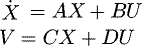 (3)where A, B, C, and D are state space, input, output, and direct transmission matrices, respectively, and U is system input. Let,
Therefore, equations (1) and (2) can be written as: (4)
(4)
 (5)
(5)
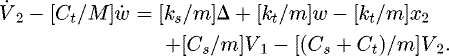
Moreover,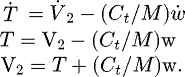 (6)
(6)
Replacing equations (6) into (5), gives: (7)
(7)
Now, (8)
(8)
Replacing V
2 from equations (6) into (4), results in: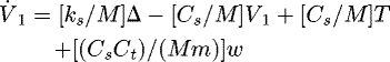 (9)
(9)
Based on equation (7), the state variables are Δ, X
2, V
1, T. The phase space matrix becomes: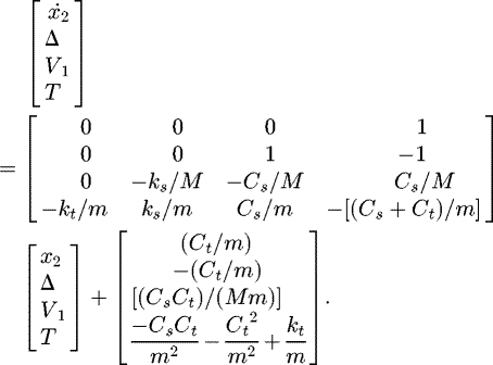
The output matrix becomes: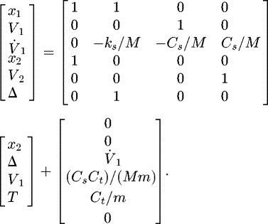
Using the above equations, the time-histories of vehicle unsprung and sprung mass velocities and displacement can be studied. Moreover, the overshoot values of unsprung and sprung mass velocities, unsprung mass displacement, and suspension travel of the quarter-car model suspension, with a step input of 0.05 m, are investigated. It is worth noting that it is regular to model both road steps and bumps, for evaluating the performance of the suspension system.
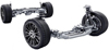 |
Fig. 1 The suspension system of the studied vehicle. |
Characteristics of vehicle mechanical system.
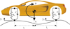 |
Fig. 2 Two-DOF model of the car with bounce and pitch motions. |
Dimensions and weights of the Mercedes-AMG SLC-43.
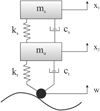 |
Fig. 3 Quarter-car model of the vehicle suspension. |
Design information on the suspension system.
3 Results and discussions
We used MATLAB software package to perform a numerical solution to find the complex conjugate pair of characteristic roots as −2.0373 + 5.3958i, −2.0373 − 5.3958i, −1.7500 + 4.9580i, −1.7500 − 4.9580i. In the complex roots, the negative real parts values indicate that the oscillation will decay with time.
The two damped natural frequencies and mode shapes for the 2-DOF quarter-car model are indicated as: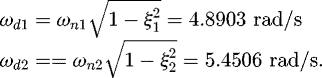 (10)
(10)
Hence: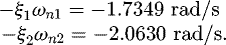 (11)
(11)
The mode shapes are calculated as: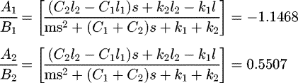 (12)
(12)
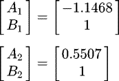 (13)
(13)
Next, we extract the natural frequencies and mode shape, in addition to the stiffness matrix and mass-matrix and the results are: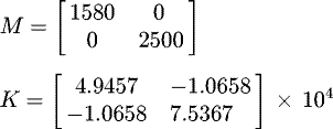 (14)
(14)
The resulting natural frequencies and mode shapes matrices are: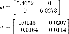 (15)
(15)
The natural frequencies are ω
n = 5.4652 rad/s and ω
n = 6.0273 rad/s and the first mode is: (16)
(16)
The second mode is: (17)
(17)
MATLAB Simulink is used to verify the results obtained above. The elements of the mode shape vectors are set as the initial condition for the integrators. Results indicate that the bounce response occurs at a damped frequency of 5 rad/s, which is in close agreement with our calculated damped natural frequency of 4.8903 rad/s. The damped natural frequency is also obtained for the second mode: (18)
(18)
A MATLAB code is used to obtain the system response to road excitation, which will clearly provide the above-mentioned transfer functions associated with this input. As mentioned above, the inputs Y
1 and Y
2 for the simulations are provided based on the assumed road surface amplitude of 10 mm and wavelength of 5 m is the car speed which is assumed to be 50 km/hr. The time period, cyclic frequency, and phase delay due to Y
2 are: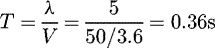 (19)
(19)
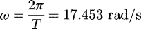 (20)
(20)
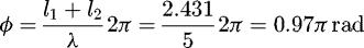 (21)
(21)
Substituting ω, ϕ and motion amplitude in the above equations result in: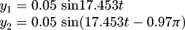 (22)
(22)
Now to determine the appropriate values of damper coefficient and spring stiffness (KS and CS ), we compare various values of damper coefficient and spring stiffness in order to figure out which one causes the suspension system to perform better. As shown in Figure 4, we obtained our results for the time histories of vehicle unsprung and sprung mass velocities and displacements.
Results for the quarter-car suspension system for step height of 0.05 m (step input) indicates that the greater the value of damping coefficient and spring stiffness, the greater the unsprung and sprung mass velocities and the unsprung mass displacement, which is not desirable for the system; however, suspension travel decreases slightly and is damped more rapidly, as seen in the output results.
The time histories of vehicle sprung mass acceleration is shown in Figure 5. For instance, although the system has a steady-state behavior after 1.5 s for all different KS and CS , it has an overshoot in the time period of 0–0.75 s, and it is clear that the greater the values of KS and CS the more overshoot will appear in results which is not appropriate.
Finally, we specifically analyzed the overshoot values for the quarter-car model suspension system for step input by obtaining the maximum values of the time history outputs of Figure 4. The resulting maximum unsprung and sprung mass velocities, maximum unsprung mass displacement and maximum suspension travel of the quarter-car model suspension, with a step input of 0.05 m, are displayed in Figure 6. As shown in Figure 6a, the maximum unsprung mass velocity, which indicates the impulse imparted to the wheel, is not affected by the values of CS and KS and therefore, the maximum value of unsprung mass velocity remains constant. Figure 6b shows that increasing spring stiffness KS will increase sprung mass velocity for different CS values. On the other hand, increasing the value of CS slightly reduces the maximum sprung mass velocity.
Figure 6c shows with increasing spring stiffness KS the maximum displacement of the unsprung mass increases, whereas, increasing values of CS slightly reduces the maximum unsprung mass displacement. For the maximum value of suspension travel, indicated in Figure 6d, it is seen that with increasing both KS and CS we will have a small suspension travel value. Although lower values of CS provide better ride quality, very low values of CS are not effective. On the other hand, high values of CS and KS result in a stiffer suspension and it is clear that the suspension will provide better handling and agility. It is worth mentioning that the suspension system should be designed with the best combination of design variables and operation parameters to provide optimum vibration performance.
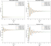 |
Fig. 4 (a) Velocity of unsprung mass (m/s),. (b) Velocity of sprung mass (m/s),. (c) displacement of unsprung mass (m). (d) suspension travel (m), for various combinations of Ks (N/m) and CS (N-s/m). |
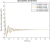 |
Fig. 5 Sprung mass acceleration (m/s2), for various combinations of Ks (N/m) and CS (N-s/m). |
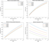 |
Fig. 6 (a) Maximum velocity of unsprung mass (m/s), (b) maximum velocity of sprung mass (m/s), (c) maximum displacement of unsprung mass (m), (d) maximum suspension travel (m), versus spring stiffness Ks (N/m) for various values of CS (N-s/m). |
4 Application of the TOPSIS method
In order to find the best value for KS
and CS
and having a good ride from the vehicle, a multi-objective optimization method has been developed with the help of the Technique for Order of Preference by Similarity to Ideal Solution (TOPSIS) multi-criteria decision-making technique.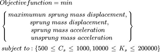
For as much as KS and CS are related to each other, first, for CS , a constant value is assumed, and all values for KS are investigated, then, a constant value for KS is assumed and all values for CS are investigated. After that, the values referring to maximum unsprung and sprung mass displacements, and unsprung and sprung mass accelerations during vehicle vibrations have been extracted. The values obtained for CS being assigned a constant value are shown in Table 4.
The values obtained for the state in which KS assumes a constant value, are shown in Table 5.
In order to obtain optimal values for KS and CS with the approach of minimizing the maximum values of unsprung mass displacement, sprung mass displacement, sprung mass acceleration, and unsprung mass acceleration, the TOPSIS method is applied.
First, the decision matrix is made according to the following relation: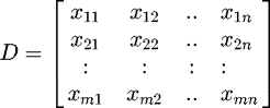 (23)where
x
ij
is value for each criterion., the decision matrix should be normalized. For normalization of values,
r
ij
is formed by the vector method. Unlike the simple linearization method, normalization is performed according to the following:
(23)where
x
ij
is value for each criterion., the decision matrix should be normalized. For normalization of values,
r
ij
is formed by the vector method. Unlike the simple linearization method, normalization is performed according to the following: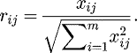 (24)
(24)
The next step is the establishment of a normal compatible matrix based on the weights of the criteria. The weights are multiplied in the normalized matrix as follows: (25)where w
j
is the weighting factor symmetric to the jth criterion.
(25)where w
j
is the weighting factor symmetric to the jth criterion. (26)
(26)
There are many ways for weighing the criteria, including Analytic Hierarchy Process (AHP), least-squares method, logarithmic least squares method, approximate methods, and Shannon entropy. In this optimization, the Shannon entropy method is used to correctly measure the criteria. The subsequent step is to calculate positive and negative desired values based on the following relationships: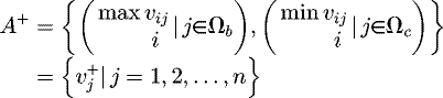 (27)
(27)
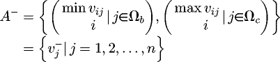 (28)
(28)
-
For positive criteria, the positive desired value is the largest value of that criterion.
-
For positive criteria, the negative desired value is the smallest value of that criterion.
-
For negative criteria, the positive desired value is the smallest value of that criterion.
-
For negative criteria, the negative desired value is the largest value of that criterion.
Here, Ω b is related to the positive indicators, while Ω c is related to the negative indicators.
In the next step, Euclidean distance from the positive and negative desired values are calculated using the following formula: (29)
(29)
 (30)
(30)
The final step is calculating the relative proximity of the desired solution. Here, the relative proximity of each option, defined in terms of the closeness value Cl is considered to be the desired solution using the following formula: (31)
(31)
The closeness value Cl is between zero and one and as it approaches unity, it is assumed to become closer to the ideal answer.
Results of TOPSIS optimization with the goal of minimizing the maximum unsprung mass displacement, sprung mass displacement, sprung mass acceleration, and unsprung mass acceleration and weighing these criteria by Shannon Entropy are presented in this Section.
As shown in Table 6, Cl has been calculated and ranked for each KS , using the Shannon entropy method, according to the rankings, the results of which are also illustrated in Figure 7, the optimum range of KS is between 130 000 and 170 000, and the most favorable is 150 000.
Also, Cl values have been calculated and ranked for each CS , as shown in Table 7. As can be seen in Table 6 and further depicted in Figure 8 with increasing CS , the optimal mode moves farther away. Therefore, the optimal mode for CS is 500.
As can be seen in Table 7 with increasing CS , the optimal mode moves farther away. Therefore, the optimal mode for CS is 500.
Based on the results of the TOPSIS optimization and the numerical results presented in Tables 6 and 7, it can be expressed that relatively large spring coefficients and low damping coefficients lead to better isolation of the sprung mass and unsprung mass from the vibrating source by minimizing maximum unsprung mass displacement, sprung mass displacement, sprung mass acceleration and unsprung mass acceleration.
The impact of variations of spring stiffness Ks in suspension performance for a given CS = 1000 N-s/m.
The impact of variations of damping coefficient in suspension performance for a given Ks = 100 000 N/m.
The closeness values obtained for various spring coefficients and ranking of the resulting performance.
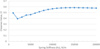 |
Fig. 7 The closeness values obtained for various spring stiffness values, using the TOPSIS method. |
The closeness value obtained for various damping coefficient and ranking of the performance.
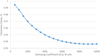 |
Fig. 8 The closeness values obtained for various damping coefficient values, using the TOPSIS method. |
5 Conclusion
A vibrational model has been discussed for a sports car suspension system. The output of the model was elaborated using MATLAB and Simulink in order to obtain characteristic roots, the natural frequencies, mode shapes, and mass and stiffness matrices. We also showed how our suspension system works in variable road conditions; for example, the accelerations and displacements of each shock absorber were presented, when the car passes a step or bumps on the road. A key finding of the paper is to compare various values of damper coefficient and spring stiffness (KS and CS ), in order to figure out which one causes better suspension system performance. In this regard, we obtained and compared the time histories of vehicle unsprung and sprung mass velocities, unsprung mass displacement, and suspension travel for various values of KS and CS in a quarter-car model. Time history results indicate that the greater the value of KS and CS , the greater the unsprung and sprung mass velocities and the unsprung mass displacement and the more overshoot will appear in the sprung mass acceleration results, none of which are desirable for the system; however, suspension travel decreases slightly and is damped more rapidly.
The maximum unsprung mass velocity, which indicates the impulse imparted to the wheel, is not affected by the values of CS and KS and therefore, remains constant. Increasing KS , will increase the maximum values of sprung mass velocity and unsprung mass displacement for different CS values and increasing the value of CS slightly reduces the maximum values. For the maximum value of suspension travel, it is seen that with increasing both KS and CS we will have a smaller suspension travel value. It is worth noting that although lower values of CS provide better ride quality, very low values of CS are not effective. On the other hand, high values of CS and KS result in a stiffer suspension and it is clear that the suspension will provide better handling and agility and the suspension should be designed with the best combination of design variables and operation parameters to provide optimum vibration performance. It was shown that suspensions with low spring stiffness and low damping rate have large suspension travels, while high damping rate results in small suspension travel and improves vehicle handling. However, it was shown that higher spring stiffness increases the maximum displacement of the unsprung mass and also sprung mass velocity.
To increase ride comfort, a multi-objective optimization with the approach of reducing maximum unsprung and sprung mass displacements, and unsprung and sprung mass accelerations, with the help of TOPSIS method has been implemented. Given that KS and CS are related to each other, to find the optimal value for each one, the other is assigned a constant value. The multi-objective optimization procedure resulted in a value of 500 for CS and 150 000 for KS .
References
- J. Marzbanrad, M. Mohammadi, S. Mostaani, Optimization of a passive vehicle suspension system for ride comfort enhancement with different speeds based on design of experiment method (DOE) method, J. Mech. Eng. Res. 5, 50–59 (2013) [CrossRef] [Google Scholar]
- M. Boreiry, S. Ebrahimi-Nejad, J. Marzbanrad, Sensitivity analysis of chaotic vibrations of a full vehicle model with magnetorheological damper, Chaos Solitons Fractals 127, 428–442 (2019) [Google Scholar]
- H. Nazemian, M. Masih-Tehrani, Development of an Optimized Game Controller for Energy Saving in a Novel Interconnected Air Suspension System, Proceedings of the Institution of Mechanical Engineers Part D Journal of Automobile Engineering, In press (2020) [Google Scholar]
- H. Nazemian, M. Masih-Tehrani, Hybrid Fuzzy-PID Control Development for a Truck Air Suspension System, SAE International Journal of Commercial Vehicles, In press (2020) [Google Scholar]
- S.-T. Zhou, Y.-J. Chiu, I.H. Lin, The Parameters Optimizing Design of Double Suspension Arm Torsion Bar in the Electric Sight-Seeing Car by Random Vibration Analyzing Method, Shock Vibration 22, 1–9 (2017) [Google Scholar]
- M. Gohari, M. Tahmasebi, Active off-road seat suspension system using intelligent active force control, J. Low Frequency Noise Vibration Active Contr. 34, 475–489 (2015) [CrossRef] [Google Scholar]
- C. Wang, X. Zhang, K. Guo, J. Lv, Y. Yang, Hierarchical optimisation on scissor seat suspension characteristic and structure, Vehicle Sys. Dyn. 54, 1538–1553 (2016) [CrossRef] [Google Scholar]
- J. Tobolár, D. Baumgartner, Y. Hirano, T. BÛnte, M. Fleps-Dezasse, J. Brembeck, Model Based Design of a Split Carrier Wheel Suspension for Light-weight Vehicles. Paper presented at the 12th International Modelica Conference, Prague, Czech Republic, May 15–17 (2017) [Google Scholar]
- J. Marzbanrad, P. Poozesh, M. Damroodi, Improving vehicle ride comfort using an active and semi-active controller in a half-car model, J. Vibration Contr. 19, 1357–1377 (2012) [CrossRef] [Google Scholar]
- H. Chen, C. Long, C.-C .Yuan, H.-B Jiang, Non-linear modelling and control of semi-active suspensions with variable damping, Vehicle Sys. Dyn. 51, 1568–1587 (2013) [CrossRef] [Google Scholar]
- V. Ozbulur, An adaptive compensator for a vehicle suspension system, J. Vibration Contr. 21, 3090–3097 (2014) [CrossRef] [Google Scholar]
- S. Gad, H. Metered, A. Bassuiny, A.M. Abdel Ghany, Multi-objective genetic algorithm fractional-order PID controller for semi-active magnetorheologically damped seat suspension, J. Vibration Contr. 23, 1248–266 (2015) [CrossRef] [Google Scholar]
- S.G. Prassad, S. Aakash, K.M. Mohan, Simulation of a Control System for an Adaptive Suspension System for Passenger Vehicles, Simulation 1, 62788 (2017) [Google Scholar]
- H.A. Hamersma, P. Schalk Els, Improving the braking performance of a vehicle with ABS and a semi-active suspension system on a rough road, J. Terramech. 56, 91–101 (2014) [Google Scholar]
- P.-C Shi, Q. Zhao, S.-S. Peng, Modeling and Simulation of Linear Two-DOF Vehicle Handling Stability, ITM Web Conf. 1, 07007 (2017) [CrossRef] [Google Scholar]
- O. Maier, B. Györfi, J. Wrede, R. Kasper, Design and validation of a multi-body model of a front suspension bicycle and a passive rider for braking dynamics investigations, Multibody Sys. Dyn. 42, 19–45 (2017) [CrossRef] [Google Scholar]
- L. Xie, J. Li, X. Li, L. Huang, S. Cai, Damping-tunable energy-harvesting vehicle damper with multiple controlled generators: design, modeling and experiments, Mech. Sys. Signal Process 99, 859–872 (2018) [CrossRef] [Google Scholar]
- R. Jiang, D. Wang, Optimization of Suspension System of Self-Dumping Truck Using TOPSIS-based Taguchi Method Coupled with Entropy Measurement, SAE Technical Paper, 2016-2001-1385 (2016) [Google Scholar]
- L. Zhang, S. Zhang, W. Zhang, Multi-objective optimization design of in-wheel motors drive electric vehicle suspensions for improving handling stability. Proceedings of the Institution of Mechanical Engineers, Part D: Journal of Automobile Engineering 233, 2232–2245 (2019) [CrossRef] [Google Scholar]
- R. Zhang, X. Wang, Parameter study and optimization of a half-vehicle suspension system model integrated with an arm-teeth regenerative shock absorber using Taguchi method, Mech. Sys. Signal Process. 126, 65–81 (2019) [CrossRef] [Google Scholar]
- G.G. Fossati, L.F.F. Miguel, W.J.P. Casas, Multi-objective optimization of the suspension system parameters of a full vehicle model, Optim. Eng. 20, 151–177 (2019) [CrossRef] [Google Scholar]
- Z. Su, F. Xu, L. Hua, H. Chen, K. Wu, S. Zhang, Design optimization of minivan MacPherson-strut suspension system based on weighting combination method and neighborhood cultivation genetic algorithm, J. Automobile Eng. 233, 650–660 (2019) [CrossRef] [Google Scholar]
- C.-L. Hwang, K. Yoon, Methods for Multiple Attribute Decision Making, Springer, Berlin, Heidelberg, 1981, pp 58–191 [CrossRef] [Google Scholar]
- R. Jiang, D. Wang, Optimization of Vehicle Ride Comfort and Handling Stability Based on TOPSIS Method, SAE Technical Paper, 2015-200-1348 (2015) [Google Scholar]
Cite this article as: S. Ebrahimi-Nejad, M. Kheybari, S.V.N. Borujerd, Multi-objective optimization of a sports car suspension system using simplified quarter-car models, Mechanics & Industry 21, 412 (2020)
All Tables
The impact of variations of spring stiffness Ks in suspension performance for a given CS = 1000 N-s/m.
The impact of variations of damping coefficient in suspension performance for a given Ks = 100 000 N/m.
The closeness values obtained for various spring coefficients and ranking of the resulting performance.
The closeness value obtained for various damping coefficient and ranking of the performance.
All Figures
|
Fig. 1 The suspension system of the studied vehicle. |
| In the text | |
|
Fig. 2 Two-DOF model of the car with bounce and pitch motions. |
| In the text | |
|
Fig. 3 Quarter-car model of the vehicle suspension. |
| In the text | |
|
Fig. 4 (a) Velocity of unsprung mass (m/s),. (b) Velocity of sprung mass (m/s),. (c) displacement of unsprung mass (m). (d) suspension travel (m), for various combinations of Ks (N/m) and CS (N-s/m). |
| In the text | |
|
Fig. 5 Sprung mass acceleration (m/s2), for various combinations of Ks (N/m) and CS (N-s/m). |
| In the text | |
|
Fig. 6 (a) Maximum velocity of unsprung mass (m/s), (b) maximum velocity of sprung mass (m/s), (c) maximum displacement of unsprung mass (m), (d) maximum suspension travel (m), versus spring stiffness Ks (N/m) for various values of CS (N-s/m). |
| In the text | |
|
Fig. 7 The closeness values obtained for various spring stiffness values, using the TOPSIS method. |
| In the text | |
|
Fig. 8 The closeness values obtained for various damping coefficient values, using the TOPSIS method. |
| In the text | |
Current usage metrics show cumulative count of Article Views (full-text article views including HTML views, PDF and ePub downloads, according to the available data) and Abstracts Views on Vision4Press platform.
Data correspond to usage on the plateform after 2015. The current usage metrics is available 48-96 hours after online publication and is updated daily on week days.
Initial download of the metrics may take a while.