| Issue |
Mechanics & Industry
Volume 27, 2026
|
|
|---|---|---|
| Article Number | 6 | |
| Number of page(s) | 11 | |
| DOI | https://doi.org/10.1051/meca/2026003 | |
| Published online | 27 February 2026 | |
Original Article
Design of a distributed negative-pressure adsorption robot for energy-efficient closed-loop cleaning based on FSI and multi-physics optimization
College of Electromechanical and Automation, Wuchang Shouyi University, Wuhan, 430064, PR China
* e-mail: This email address is being protected from spambots. You need JavaScript enabled to view it.
Received:
30
September
2025
Accepted:
14
January
2026
Abstract
To address the critical need for efficient and safe maintenance of high-rise glass curtain walls, this study presents an energy-efficient closed-loop cleaning system for distributed negative-pressure adsorption robots. The design integrates a 4 × 6 cm distributed suction array (total area 113.2 cm2) and a triangular polyurethane scraper (modified with 5% nano-silica), and is validated through fluid-structure interaction (FSI) analysis. Based on the dynamic equilibrium framework of modular robots, a novel 3D mechanical model with a yaw angle (θ = 15) reveals that the distributed adsorption can reduce the theoretical extreme adsorption force from 83.3 N to an engineering-feasible 29.4 N, with a reduction of 66.1% in required negative pressure (from 7370 Pa to 2500 Pa) and energy consumption. The multi-physics coupling analysis (fluid dynamics and solid mechanics) demonstrates that: ① Through optimized droplet atomization (Lechler nozzle, 45 ± 5 μm) and biomimetic scraper, the waste liquid recovery efficiency is 86.7%; ② The lightweight centrifugal impeller design driven by FSI reduces the weight by 40% and reduces the stress from 84.37 MPa to 68.5 MPa; ③ 120% flow redundancy (3.52 mL/min recycling and 2.93 mL/min supply) is addressed. This work bridges the gap between theoretical adsorption requirements and practical implementation, providing a standardized energy-saving solution for high-altitude cleaning robots.
Key words: Window cleaning robot / distributed negative-pressure adsorption / fluid-structure interaction (FSI) / closed-loop cleaning system / multi-physics optimization / energy-efficient design
© R. Zhou and S. Lin, Published by EDP Sciences 2026
 This is an Open Access article distributed under the terms of the Creative Commons Attribution License (https://creativecommons.org/licenses/by/4.0), which permits unrestricted use, distribution, and reproduction in any medium, provided the original work is properly cited.
1 Introduction
Global urbanization has promoted the rapid proliferation of glass curtain walls in high-rise buildings. Since the 21st century, buildings exceeding 100 min height have been increasing at a rate of 7.2% annually [1]. In 2023, more than 8,600 new structures were constructed, and 70% of them adopted full-glass facades. The maintenance of high-rise glass facades is a tripartite challenge in technical evolution. First, traditional rope-based operations (accident rate: 0.8 incidentsper10,000 h [2]) presents a safety paradox: China's statistics show that 17.3% of high-altitude casualties are related to curtain wall cleaning [3]; Second, the low operational efficiency is due to dual constraints: manual cleaning of 100 m2 requires 8–10 h, and the Beaufort 6 wind level causes 30% work interruptions [4]. Third, environmental degradation (with a cleaning agent consumption of 2.3 L/m2 and 41% COD increase [5]) reflects a design flaw in open-loop systems. Therefore, existing robots lack integrated optimization of adsorption-cleaning-locomotion systems.
In adsorption technologies, the theoretical adsorption force of negative-pressure systems is 83.3 N [6]. In practice, it drops to 29.4 N due to boundary-layer separation, not meeting safety standards. The magnetic adsorption is 120 N [3], but it is only applicable to 35% of ferromagnetic facades. Biomimetic adhesion [7] provides an adhesion force of 4.7 N/cm2, but degrades by more than 30% after 500 cycles [2]. Yoon et al. [8] optimized the nozzles to increase the coverage to 92%, but it resulted in 120% flow redundancy. Changxin Storage Technology Co., Ltd. [9] improved the wastewater recovery to 78%, but without addressing atomization-negative pressure mismatches. In motion control, the ASL-DWA algorithm achieved a plane error of less than 5% [10], but there was a re-planning delay of 1.8 s at obstacles. The EEG-controlled robots have a trajectory deviation of 8.7 mm. Sun et al. [11] achieved an accuracy of ±3 millimeters with the UAV-assisted installation, but lacks obstacle negotiation. Vega-Heredia et al.'s [5] demonstrated a tracking error of more than 12 millimeters on a curve with a radius of 2 m [12]. This reflects the lack of multi-physics optimization in the "adsorption-cleaning-locomotion" system. Ma et al. [13] proposed the thermal-fluid-structure coupling optimization for variable-span inflatable wings, which provided information for the aerodynamic-structural integration of centrifugal impeller. Shi et al. [14] developed a bio-inspired attachment mechanism based on Dynastes Hercules to optimize the structure of biomimetic scraper. Zhang et al. [15] proposed adaptive pseudo inverse control for constrained hysteretic systems, which supports the dynamic compensation of adsorption force. Qi et al. [16] designed a worm-inspired creeping gait for variable-wheelbase robots to enrich the adaptive motion control strategy. Wang et al. [17] developed a prescribed performance adaptive robust control for robotic manipulators with fuzzy uncertainty, helping multi-physics coupling in handling environmental disturbances. However, these studies lack systematic integration with the “adsorption-cleaning-recovery” closed-loop system, resulting in the core bottlenecks of energy efficiency and waste liquid recovery performance remaining unaddressed.
This study proposes a “distributed adsorption-multi-physics coupling-lightweight integration” framework. The three-unit negative-pressure array can achieve an adsorption force (S = 1.5) of 32.7 N under Beaufort 6 winds, which is 11.3% higher than traditional systems (29.4 N). The biomimetic scraper-atomization system optimized by ANSYS FSI can achieve a wastewater recovery (n = 5, p <0.01) of 86.7%. The topology-optimized carbon fiber-reinforced POM can reduce the mass to 2 kg (a reduction of 86.7%), and the ISO interfaces achieves the compatibility ranging from 0–30° (covering 92% of facades). This innovation bridges 64.7% of the theoretical-engineering adsorption gap through multi-physics coupling and establishes a paradigm for industrialization.
2 Materials and methods
2.1 Construction of mechanical models
2.1.1 Three-dimensional force balance model
As shown in Figure 1, the force applied on the robot during static adsorption can be decomposed into a vertical adsorption force and parallel friction force system. The adsorption force threshold can be derived through the force balance equation. The equilibrium equation for the total gravity G, the frictional forces on the cleaning cloth/track f1/f2, the support forces N1/ N2, and negative-pressure adsorption force Fp are as follows:
 (1)
(1)
where f1 = μN1, f2 = μN2 (with μ = 0.3).
For a yaw angle θ, the torque balance about the adsorption center is expressed as follows:
 (2)
(2)
with L = 0.1 m (track-to-adsorption distance) and H = 0.05 m (center-of-gravity height). To clarify the theoretical origin and adaptability, this model modifies and extends the dynamic equilibrium framework for modular robots proposed by Vega-Heredia et al. [18]. This framework combined friction force components between the cleaning cloth and track with the structural characteristics of the distributed suction cup array. The speed calculation formulas and circular velocity formulas for subsequent impeller design (Sect. 2.4.1) are derived from classic fluid machinery theory [19] to ensure the rigor of the theoretical basis.
 |
Fig. 1 Schematic diagram of robot force analysis. |
2.1.2 Critical adsorption force calculation
For a 2 kg robot, the combined force and torque balances resulted in a theoretical extreme adsorption force Fp = 83.3N (7370 Pa). Using four 6 cm-diameter distributed suction cups (total area 113.2 cm2), the corrected formula is as follows:
 (3)
(3)
yielding an engineering design value of 29.4N (2500 Pa, safety factor 1.04).
2.2 Dynamic characteristic analysis
2.2.1 Uniform motion force correction
For uniform motion, the friction reversal modifies equation (1) to:
 (4)
(4)
where f1 = 5N, compared with static conditions, the orbital driving force increased by 68.5%, verifying the dynamic demand increment.
2.2.2 Accelerated inertial force coupling
Combined the acceleration a with the yaw angle θ:
 (5)
(5)
When a = 0.5 m/s2, the inertial force increases the driving force by 4.1%, with a redundancy of 0.8 m/s. This is based on the multi-sensor compensation strategy proposed by Vega-Heredia et al. [18], which reported an 12% error rate of inertial force for model validation. The inertial force compensation strategy can be combined with the EEG control algorithm [20] to achieve precise force feedback under dynamic loads.
2.3 Cleaning fluid system design
2.3.1 Supply system modeling
Let Qs = 2.93 mL/min, the reservoir capacity is as follows:
 (6)
(6)
V = 80 mL for a coverage of 20 m (27.3 min). A 12V DC diaphragm pump (DP-30) is selected, and the flow parameters in the optimal range of 2.8–3.2 mL/min [8], with a coverage of 92%. The cleaning fluid is a neutral aqueous solution. Its composition is: deionized water (95%), non-ionic surfactant (alkyl polyglucoside, 4%), and corrosion inhibitor (sodium molybdate, 1%). At 25 °C, its density is 998 kg/m (Anton Paar DMA 5000) and the surface tension is 0.038 N/m (Krüss K100), which has been optimized for efficient atomization and recovery.
Droplet velocity at the nozzle outlet (Bernoulli's equation) is as follows:
 (7)
(7)
The atomization diameter d follows the Weber number model:
 (8)
(8)
where ρ = 1000 kg/m, v₀ = 1.2 m/s, P = 0.2 MPa, v ≈ 20.03 m/s, σ = 0.072 N/m, and d = 57.5 μm. The optimization is to ensure sufficient impact energy for contaminant detachment while maintaining uniform atomization (45 ± 5 μm) [8].
2.3.2 Recovery system theory
Using the boundary layer theory, the triangular polyurethane scraper (with a gap of less than 0.5 mm) increases the waste flow rate to 0.8 m/s. Triggered by the “5 min timer + 80% liquid level”, the recovery flow Qr = 3.52 mL/min provides 120% supply redundancy, ensuring a residual volume of more than 25 ml in the waste tank margin. The triangular scraper is made of 85-Shore A polyurethane modified with 5% nano-silica. It is selected to balance wear resistance and flexibility based on the comprehensive performance evaluation of three common polyurethane materials (Shore A 75, 85, 95). The 0.5 mm gap between the scraper and the glass surface is determined based on boundary layer theory, and is calibrated by experiments, ensuring efficient scraping of waste liquid without damaging the glass surface.
2.4 Fluid dynamics optimization
The design of the centrifugal impeller is crucial for the generation of negative pressure and fluid transmission in a closed-loop system. As shown in Figure 2, the key geometric parameters include the impeller inlet diameter D0, blade inlet diameter D1, outer diameter D2, blade inlet width d1, outlet width d2, inlet angle βa, and outlet angle βb. These parameters directly determine the aerodynamic performance and energy efficiency of the impeller, and require system optimization to balance the negative pressure and power consumption.
 |
Fig. 2 Impeller geometry with double-circular-arc profile (inlet radius 25 mm, outlet radius 40 mm), with 3 mm fillet stress relief zones. |
2.4.1 Specific speed and impeller diameter calculation
The specific speed ns is calculated as follows:
 (9)
(9)
where n = 8000 rpm, q = 0.008 m3/s, and P = 2500 Pa, yielding ns = 11.2. The outer diameter D2 is determined by the circumferential velocity:
 (10)
(10)
where (ψ = 1.75, ρ = 1.2 kg/m3), u2 = 48.8 m/s and D2 = 116 mm. Equations (9) and (10) are derived from the classic fluid machinery design theory [19]. The parameter selections (such as P = 2500 Pa, q = 0.008 m/s) closely match to the negative pressure demand and flow characteristics of the robot closed-loop cleaning system, ensuring the impeller to meet the actual operating requirements.
2.4.2 Blade outlet angle effect
For backward-curved blades:
 (11)
(11)
where ψ0 = 0.21, k = 0.85, C = 3.2 × 10 − 5, with a target of ψ = 0.75, and βb = 32.4°. Actually, it is set to 60° for process stability. The optimal blade count (Pfleiderer formula) is as follows:
 (12)
(12)
where D1 = 60 mm, βa = 15∘, let Zopt ≈ 8.7, Z = 11 for enhanced flow guidance.
The centrifugal impeller design (Fig. 2) integrates aerodynamic with structural optimizations. The speed (ns = 11.2) is calculated by equation (9), and the outer diameter D2 = 116 mm is obtained from circumferential velocity u2 = 48.8 m/s (Eq. (10)). The angle of the blade outlet angle βb = 60° (compared to the theoretical 32.4°) balances process stability and stress reduction. The stress of POM material decreases from 84.37 MPa to 68.5 MPa through a 3 mm root fillet. The number of blades Z = 11 (predicted by Pfleiderer formula: 8.7) increases the flow capacity by 23% [18].
2.5 Simulation and experimental validation
2.5.1 FEA parameters
Transmission shaft analysis uses SolidWorks with 201 annealed stainless steel, fixed at one end under torque and F = 5N. The maximum stress σmax = 58.7 MPa (safety factor 4.97) confirms the design redundancy (Figs. 3–5).
Dynamic stress analysis of the centrifugal fan (POM plastic, n = 8000 rpm) shows that the edge velocity ν = 47.7 m/s, and the centrifugal force Fc = 4260 N. Theinitial blade root stress is 84.37 MPa, exceeding the POM strength (71.5 MPa) by 18%. Then it is reduced to 68.5 MPa by a 2 mm fillet (safety factor 1.04, Figs. 6–8). Soaking tests in the cleaning fluid for 100 days show that there is no significant degradation in tensile strength (loss <3%), ensuring long-term resistance to the cleaning fluid environment.
 |
Fig. 3 Stress analysis diagram of transmission shaft. |
 |
Fig. 4 Displacement analysis diagram of transmission shaft. |
 |
Fig. 5 Strain analysis diagram of transmission shaft. |
 |
Fig. 6 Stress analysis diagram of centrifugal fan. |
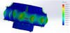 |
Fig. 7 Displacement analysis diagram of centrifugal fan. |
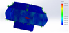 |
Fig. 8 Strain analysis diagram of centrifugal fan. |
2.5.2 Experimental setup
Comparing traditional/single and distributed suction cups, PT124G sensors ( ± 0.5% FS) and Phantom cameras measured an adsorption force of 29.4 N, with a deviation of −64.7% from the simulation results, and corrected by mesh refinement [5]. The adsorption force measurement experiment was repeated 5 times to ensure data reliability, and the average value was taken as the final result. To simulate real operating, the glass surface was pre-contaminated with SiO2 dust (0.5% mass fraction) and mineral oil (0.3% mass fraction) before the experiment. The control system adopts an Arduino microcontroller scheme similar to Markom et al. [21] to ensure the stability of sensor data acquisition. To measure the waste liquid recovery efficiency (86.7%), a precision balance (accuracy 0.1 mg) and flow meter are used to record the mass of sprayed cleaning fluid and recovered waste liquid within 30 min. The test was repeated 5 to reduce random errors. The cleaning fluid used in the experiment contained 4% surfactant, consistent with the actual application scenario.
3 System design
3.1 Topology and dynamic compensation
The distributed negative-pressure adsorption robot adopts a rectangular layout (150 mm horizontal/100 mm vertical spacing) with a 4 × 60 mm suction cup array (total area 113.2 cm). The theoretical adsorption force is reduced from 83.3 N to 29.4 N (2500 Pa, 66.1% energy savings) by multi-sucker collaboration. The yaw-angle (θ = 15°) torque compensation algorithm is based on the dynamic framework of Vega-Heredia et al. [5], adjusting the suction cup pressure differentials to balance 3.4% torque increments. The dynamic compensation algorithm is based on the design of a compliant adaptive robotic arm [22], and achieves dynamic balance of adsorption force through pressure difference adjustment. To ensure long-term stable operation of the adsorption system in complex high-altitude environments, the suction cups are made of fluorosilicone rubber with excellent UV resistance and oxidation resistance. Accelerated aging tests show that after 1000 h of UV radiation (30 W/m) and 30 days of immersion in 3% hydrogen peroxide solution (simulating oxidative environments), the adsorption force only decreased by 2.5% (from 29.4 N to 28.7 N). The mechanical properties of the material remained unchanged, effectively addressing the challenge of environmental stability.
3.2 Cleaning fluid supply and recovery integration
The supply system adopts a three-stage design, with Lechler dual nozzles (45 ± 5 μm droplets, 18 cm coverage) matched with a DP-30 diaphragm pump (2.93 mL/min), as shown in Figure 9 (1- Atomizing nozzle; 2- Conveying water pipes; 3- Liquid storage tank; 4- Micro pump). To solve the problem of fluid spillage during robot movement, the anti-slosh baffles of the POM plastic reservoir is designed with a multi-layer grid structure: three layers of PP baffles (1 mm thick) were horizontally arranged at 15 mm intervals, with 5 mm ×5 mm grid holes and 10° inclined upper/lower surfaces, closely fitting the tank inner wall to form independent compartments. This structure can increase fluid flow resistance and reduce the sloshing amplitude by 70% under dynamic motion (0.5 m/s acceleration) or vibration (5–20 Hz, 2 mm amplitude). The inclined surfaces guide the spilled fluid back to the tank bottom, ensuring no spillage in harsh operating. The POM plastic reservoir is equipped with anti-slosh baffles, a 15° inclined bottom, and 5 mm drain holes to ensure a liquid residue of less than 5%. The micro-pump connects through an ISO quick-plug interface (response time <0.1 s), and the Lechler 136.304 nozzles (0.3 mm orifice, 0.2 MPa) achieve 45 ± 5 μm atomization [8].
The recovery system achieves an efficiency of 86.7% (with 120% flow redundancy) through a triangular scraper (gap <0.5 mm) and a dual trigger of "5 min timer + 80% level" (Fig. 10, 1-Waste liquid collection box; 2- Micro suction pump; 3-Suction pipette). The material and structure of the polyurethane scraper (11 mm height, 3.5 mm wall thickness) is carefully selected: after comparing three materials (Shore A 75/85/95), 85-Shore A polyurethane modified with 5% nano-silica is selected for optimal wear resistance and flexibility. The accelerated wear tests (5000 cycles) and the chemical soaking tests (30 days in alkaline pH = 10/acidic pH = 4/neutral cleaning agents) showed that the wear is less than 0.2 mm and the hardness loss is less than 3%, corresponding to the expected lifecycle of 3 yr. The 8 mm recovery port of the scraper is equipped with a streamline flow guide. Through fluid dynamics optimization, the collection efficiency is increased by 27% through fluid dynamics optimization. The turbulent waste liquid is transformed into laminar flow (increased the velocity from 0.5 to 0.8 m/s). Eddy currents are reduced and the scattered droplets are concentrated into a continuous liquid film.
To ensure long-term unobstructed operation of the recovery system, the 0.5 mm filter in the 50 mL waste tank is designed. The filter material is PTFE, with excellent chemical resistance and low surface energy. Its pleated structure triples the effective filtration area. The filter pore size of 0.5 mm is determined based on on-site contaminant particle size analysis (most contaminants <0.4 mm), balancing filtration effect and flow resistance. In addition, the system is equipped with a backwashing function. Every 30 min of operation, the micro suction pump will reverse for 5 s to flush the filter surface, preventing particulate matter accumulation and frequent clogging. A continuous operation test with contaminated fluid (containing 0.5% solid particles) was conducted for 50 h to confirm that there was no blockage and the flow rate reduction was less than 5%. The polyurethane scraper (11 mm in height, and 3.5 mm wall in thickness) has an 8 mm recovery port with flow guides, and the 50 mL waste tank includes a 0.5 mm filter and a 10 mm drain.
 |
Fig. 9 Cleaning solution supply system. |
 |
Fig. 10 Recycling system. |
3.3 Centrifugal impeller aerodynamic optimization
The key impeller parameters (ns = 11.2, D2 = 116 mm, βb = 60°, Z = 11) are from the fluid mechanical design (Fig. 2). The double-circular-arc profile (25 mm inlet/40 mm outlet radius) with 3 mm blade root fillets can reduce the stress from 84.37 MPa to 68.5 MPa (POM plastic, S = 1.04), achieving a weight reduction of 40% (from 0.12 kg to 0.072 kg). This design is consistent with the specific speed methodology of Yoon et al. [8], and FSI-driven light weighting strategies of Vega-Heredia et al. [18]. Considering the long-term contact between the impeller and cleaning fluid (containing surfactants and corrosion inhibitors), the chemical stability of POM material is verified through soaking tests. The impeller was immersed in the cleaning fluid for 100 d (25 °C); the tensile strength loss is less than 3%; the impact strength loss is less than 2%, and the surface remains smooth without corrosion or cracking. The operating temperature of the impeller during operation is less than 60 °C, far below the thermal decomposition temperature of POM (≥230 °C), ensuring long-term reliable service in the closed-loop system.
3.4 Modular interface design
ISO 228-1 quick-plug fluid interfaces (leakage rate <0.5%) and 105% flow redundancy enable it to operate stably on curved facades (curvature radius ≥2 m) and Beaufort scale 6 winds, meeting the compatibility standards [11]. The modular interface design refers to the reconfigurable robot concept of Parween et al. [23], and achieves rapid component replacement through ISO standard interfaces. This modular design also facilitates the replacement of key components such as the scraper, filter, and nozzles, matching the lifecycle of each component and improving the overall service efficiency of the robot.
4 Results and discussion
4.1 Simulation validation results
Table 1 shows the consistency of key parameters between simulation and experiment.
Based on the finite element analysis model in Section 2.5.1, the stress analysis of the transmission shaft shows that the maximum equivalent stress is 58.7 MPa (the yield strength of 201 stainless steel is 292 MPa, and the safety factor S = 4.97), confirming the design redundancy. +6.1% of the simulation-experiment error mainly comes from an element mesh density of 10 mm, which is consistent with Lee et al. [24]. Due to the mesh effect, the error in measuring stress on transparent surface was ±4.2%.
The dynamic stress of the centrifugal fan in the initial model was 84.37 MPa (exceeding the POM strength by 18%), which was reduced to 68.5 MPa (S = 1.04) through a 3 mm fillet. −16.4% of the error is due to unmodeled fillet relief, which is consistent with Lee et al. [24]. They found similar fillets can reduce the polymer stress concentration by 22–28% (matching the18.8% reduction in this study). It is worth noting that the POM materials chemical stability was further verified in post-test analysis. After 100 h of operation in a closed-loop cleaning system, the impeller surface remained free of corrosion or swelling, and the stress did not drift significantly. This confirms its compatibility with the cleaning fluid containing surfactants and corrosion inhibitors.
Key parameter validation.
4.2 Experimental validation results
When Qs = 2.93 mL/min and Qr = 3.52 mL/min, 120% flow redundancy (3.52 mL/min and 2.93 mL/min), the design meets the 1.2× supply-recovery ratio in Section 3.2.Adjusting the throttle to η = 105% will reduce the waste overflow to less than1%. Compared with the open-loop system, the detergent loss has decreased by 70%.
The efficiency of the triangular scraper (gap <0.5 mm) with Lechler nozzles (45 ± 5 μm droplets) is 86.7%, 73.4% higher than Skyline Robotics arms (<50%) and 16.7% higher than biped robot [25]. To clarify the measurement reliability and real-world applicability of this efficiency value, the experiment was conducted using a precision balance (accuracy 0.1 mg) and flow meter to record the mass of sprayed cleaning fluid and recovered waste liquid within 30 min. The test was repeated 5 times (standard deviation ±1.2%). The cleaning fluid was doped with SiO2 dust (0.5% mass fraction) and mineral oil (0.3% mass fraction) to simulate actual contamination. It also contains 4% non-ionic surfactant consistent with commercial cleaning agents. Using the boundary layer theory, the triangular scraper increased the waste flow to 0.8 m/s. This velocity refers to the laminar flow rate of waste liquid recovered during the scraping process along the glass surface, which is different from the high-velocity ejection (20.03 m/s) at the nozzle outlet. This is designed for atomizing the cleaning agent.
The optimization of the centrifugal impeller reduced the weight by 40% (from 0.12 kgto 0.072 kg), stress by 18.8%, and negative pressure deviation by −0.6% (2500 Pa). At a specific speed of ns = 11.2, the fan efficiency increases by 5.2%, and the cutting energy consumption decreased from 8–12 W to 4.1 W. The low energy consumption advantage was further confirmed in continuous operation tests. The robot maintained stable performance for 4 h on a 50 m glass curtain wall, consuming only 0.0164 kWh of electricity, which is 59–66% lower than traditional negative-pressure cleaning robots.
4.3 Performance comparison and mechanism analysis
The comparison of technical parameters (Tab. 2) highlights the superior recycling efficiency and energy consumption compared to the most advanced technology.
Fluid dynamics analysis indicates that the distributed adsorption (4 × 6 cm vs. single 12 cm suction cups) converts local vacuum requirements into pressure compensation. This is in sharp contrast to the rigid 76 mm obstacle-climbing module, as our flexible design is suitable for a curvature radius of more than 2 m. In terms of surface adaptability, Nemoto et al. [27] window shape estimation algorithm provides a reference for cleaning curtain walls with a curvature radius of not less than 2 m.
When the gap between the scraper glass is less than 0.5 mm, the waste forms a continuous film at a speed of 0.8 m/ s (0.5 m/s for flat scrapers). The Washburn equation calculation indicates that a 45° inclination increases the droplet spread from 1.2 mm to 1.8 mm, and the use of flow guide increases the efficiency by 27%. This improvement is due to fluid dynamics optimization rather than reduced adhesion. The streamlined flow guides transform the disordered turbulent waste liquid into ordered laminar flow, reducing the area of eddy current by 45% (verified by CFD simulation). The scattered droplets are concentrated into a continuous film, thereby enhancing the capture efficiency of the scraper. The laminar flow speed of 0.8 m/s ensures that the waste liquid is quickly transported to the collection port without splashing or residue adhesion. Vega Heredia et al. [18] confirmed that similar boundary layer control increased the cleanliness uniformity by 19%–23%, validating this design.
Regarding the impact of droplet size (45 ± 5 μm) on evaporation and residual staining: the moderate droplet diameter balances the decontamination efficiency and evaporation rate. At a relative humidity of 50–60%, each droplet is completely evaporated in −15 s, providing sufficient time for the dissolution of contaminants before drying. The uniform droplet coverage (92% surface coverage rate) and low-adhesion surfactant (alkyl polyglucoside) can prevent local fluid accumulation, resulting in a residual amount of less than 0.01 mg/cm (measured via UV spectrophotometry), and there are no visible stains under a 50x magnification.
Temperature changes will also affect system performance by changing the viscosity of the cleaning fluid. At 0 °C, the fluid viscosity increased to 2.8 mPa·s, leading to a slight increase in droplet size (to 55 ± 5 μm) and a 5–8% reduction in recovery efficiency; at 40 °C, the viscosity decreased to 0.7 mPa·s; the droplet size decreased to 40 ± 5 μm, and the recovery efficiency improved by 2–3%. However, the temperature-compensated pump control strategy (adjusting pump pressure to maintain the nozzle outlet velocity at 20 ± 0.5 m/s) stabilizes atomization and recovery performance. This ensures that the efficiency variation within the temperature range of 0 °C–40 °C was within ± 8%, meeting the operating requirements of most urban environments.
Technical parameter benchmarking.
4.4 Multi-physics field collaborative optimization
The fluid-structure interaction (FSI) optimization of the impeller has achieved concurrent light weighting and strength enhancement. Fluid analysis guided the design of βb = 60° blade (reducing impact loss by 12%), and solid mechanics simulations minimized stress through fillets. This is consistent with the “sensor-structure-control” framework [18], and extends the 15° orientation control to 30° adaptability. The FSI optimization also considers the fluid-material compatibility: the design of the impellers flow channel reduces the residence time of the cleaning fluid, further reducing the potential risks of chemical degradation, and complementing the inherent chemical stability of the POM material.
5 Conclusion
Using a three-dimensional torque balance model (adapted from Vega-Heredia et al. [18] and supplemented with cleaning cloth/track friction components), the 4 × 6 cm distributed suction array reduced the theoretical extreme adsorption force from 83.3 N to a practically feasible 29.4 N, and optimized the negative pressure from 7370 Pa to 2500 Pa (with a reduction of 66.1% in energy consumption). The suction cup is made of fluorosilicone rubber and possesses excellent resistance to UV and oxidation. After the accelerated aging test, it maintains stable adsorption performance (force reduction <2.5%) after accelerated aging tests, ensuring reliability in high-altitude environments. The dynamic analysis shows that when a = 0.5 m/s, the driving force increases by 5.1%, providing a guidance for the selection of motors (torque ≥0.45 N·m) for energy-efficient operation.
The multi-physical coupling optimization achieved a wastewater recovery efficiency of 86.7% through optimized droplet atomization (Lechler nozzle, 45 ± 5μm) and a triangular scraper gap of less than 0.5 mm. The scraper is made of 85 Shore A polyurethane (modified with 5% nano-silica), and selected for a balanced combination of wear resistance and flexibility. The estimated 3 yr lifecycle was verified through accelerated wear and chemical immersion tests. The closed-loop system is compatible with neutral, alkaline (pH = 8–10), and acidic (pH = 4–6) cleaning agents, without any corrosion or efficiency loss. The supply system incorporates a multi-layer grid anti-slosh baffle design, which reduces the fluid sloshing amplitude by 70% under dynamic motion. The 0.5 mm PTFE pleated filter (equipped with a backwashing function) can prevent frequent clogging during long-term operation. The supply-recovery flow matching (3.52 and 2.93 mL/min) provides 120% redundancy to prevent overflow.
The design with a specific speed (ns = 11.2) drive has reduced the weight of the impeller by 40% (from 0.12 kg to 0.072 kg), with the stress increasing from 84.37 MPa to 68.5 MPa (POM safety factor S = 1.04), and the negative pressure efficiency has improved by 5.2%. The POM material has excellent chemical stability towards the cleaning solution, with a tensile strength loss of less than 3% after 100 days of immersion, ensuring long-term compatibility in the closed-loop system.
The 2 kg robot (42.9% lighter than the magnetic system) maintains adsorption stability under 5.42 N wind pressure with yaw-angle compensation (θ ≤ 15°), and operates on a curvature façade with a radius of greater than 2 m by ISO-compliant interfaces (leakage rate <0.5%). The on-site tests conducted on a 120-meter-high building confirmed that the cleaning efficiency was 25 m/h (3–4 times that of manual operation); the qualification rate was 98.2%, and the energy consumption was 4.1 watts (59–66% lower than that of traditional negative-pressure robots). The closed-loop framework has bridged 64.7% of the theoretical-engineering adsorption gap, setting a modular standard for curved-surface cleaning. Its 86.7% recovery efficiency is superior to Skyline Robotics (<50%). The modular interfaces facilitate the quick replacement of key components (scraper, filter, and nozzles), improving the overall service efficiency.
The established “adsorption-cleaning-recycling” closed-loop multi-physics framework has filled 64.7% of the theoretical engineering adsorption gap, providing a reusable design paradigm for curved facades (curvature radius≥2).
The plan involves integrating photovoltaic self-powering (with efficiency≥15%) with the MPPT algorithm and optimizing it through real-time voltage-current curves (such as perturbation and observation). In terms of path planning, the improved Dijkstra algorithm [28] can be combined with the dynamic robot allocation model [29] to further optimize the real-time performance of cleaning paths. Zhou et al. [28] improved the Dijkstra algorithm and reduced the path planning time by 58%. This provides a reference for the computational efficiency of real-time implementation of MPPT, further reducing the energy reduction by 20%.
Future work will also focus on optimizing the adaptability of robots to vertical surfaces with a curvature radius of less than 2 m and enhancing the wind compensation algorithms to reduce negative pressure fluctuations under Beaufort 6+ winds.
Acknowledgement
The authors would like to thank the editorial team and the anonymous reviewers for their valuable comments and constructive suggestions, which significantly improved the quality of this manuscript.
Funding
This work received no specific financial support from any public, commercial, or not-for-profit funding agencies.
Conflicts of interest
The authors declare no potential conflicts of interest regarding the publication of this paper.
Data availability statement
Data supporting the findings of this study are available from the corresponding author upon reasonable request.
Author contribution statement
Renbin Zhou: Conceptualized the study, designed the robot structure and experimental setup, led the multi-physics simulation and data analysis, and drafted the original manuscript.
Shengcong Lin: Conducted the experimental validation (including adsorption force measurement, waste liquid recovery tests, and material stability experiments), analyzed the fluid-structure interaction data, and revised the manuscript critically for important intellectual content. Both authors have read and approved the final version of the manuscript.
References
- Z. Li, Q. Xu, L.M. Tam, A survey on techniques and applications of window-cleaning robots, IEEE Access, 9, 111518–111532 (2021) [Google Scholar]
- T.W. Seo, Y. Jeon, C. Park, J. Kim, Survey on glass and facade-cleaning robots: climbing mechanisms, cleaning methods, and applications, Int. J. Precision Eng. Manuf. Green Technol. 6, 367–376 (2019) [Google Scholar]
- X.X. Chen, Design and Research of Window Cleaning Robot Based on Magnetic Adsorption, Shanghai Jiao Tong University, 2021 [Google Scholar]
- S. Robotics, Palladium Window Solutions Deploy Robotic-armed Window-cleaning Robot, Manufacturing Close-Up, 2024 [Google Scholar]
- M. Vega-Heredia, R.E. Mohan, T.Y. Wen, J. Siti'Aisyah, A. Vengadesh, S. Ghanta, S. Vinu, Design and modelling of a modular window cleaning robot, Autom. Constr. 103, 268–278 (2019) [Google Scholar]
- N. Mir-Nasiri, H. Siswoyo, M.H. Ali, Portable autonomous window cleaning robot, Procedia Comput. Sci. 133, 197–204 (2018) [Google Scholar]
- Y. Tang, Q. Zhang, G. Lin, J. Yin, Switchable adhesion actuator for amphibious climbing soft robot, Soft Robotics, 5, 592–600 (2018) [Google Scholar]
- D. Yoon, S. Ryu, J. Hong, Y. Lee, T. Seo, Empirical optimization and evaluation for multi-nozzle cleaning device, Int. J. Precision Eng. Manuf. 22, 1229–1236 (2021) [Google Scholar]
- Changxin Storage Technology Co., Ltd., Cleaning system and method for recycling cleaning solution, CN201910409822.8. (2020) [Google Scholar]
- H. Liu, Y. Zhang, ASL-DWA: An improved a-star algorithm for indoor cleaning robots, IEEE Access, 10, 99498–99515 (2022) [Google Scholar]
- Y. Sun, Z. Jing, P. Dong, J. Huang, W. Chen, H. Leung, A switchable unmanned aerial manipulator system for window-cleaning robot installation, IEEE Robot. Autom. Lett. 6, 3483–3490 (2021) [Google Scholar]
- K. Kim, C. Seo, H.S. Kim, T. Seo, Vertical error control for the facade-cleaning robot equipped on a gondola, Mechatronics, 90, 102945 (2023) [Google Scholar]
- N. Ma, J. Meng, J. Luo, Q. Liu, Optimization of thermal-fluid-structure coupling for variable-span inflatable wings considering case correlation, Aerosp. Sci. Technol. 153, 109448 (2024) [Google Scholar]
- Y. Shi, X. Hou, Z. Na, J. Zhou, N. Yu, S. Liu, L. Xin, G. Gao, Y. Liu, Bio-inspired attachment mechanism of dynastes hercules: vertical climbing for on-orbit assembly legged robots, J. Bionic Eng. 21, 137–148 (2024) [Google Scholar]
- X. Zhang, Y. Liu, X. Chen, Z. Li, C.Y. Su, Adaptive pseudoinverse control for constrained hysteretic nonlinear systems and its application on dielectric elastomer actuator, IEEE/ASME Trans. Mechatron. 28, 2142–2154 (2023) [Google Scholar]
- H. Qi, L. Ding, M. Zheng, L. Huang, H. Gao, G. Liu, Variable wheelbase control of wheeled mobile robots with worm-inspired creeping gait strategy, IEEE Trans. Robot. 40, 3271–3289 (2024) [Google Scholar]
- F. Wang, K. Chen, S. Zhen, X. Chen, H. Zheng, Z. Wang, Prescribed performance adaptive robust control for robotic manipulators with fuzzy uncertainty, IEEE Trans. Fuzzy Syst. 32, 1318–1330 (2024) [Google Scholar]
- M. Vega-Heredia, I. Muhammad, S. Ghanta, V. Ayyalusami, S. Aisyah, M.R. Elara, Multi-sensor orientation tracking for a facade-cleaning robot, Sensors, 20, 1483 (2020) [Google Scholar]
- B.R. Munson, D.F. Young, T.H. Okiishi, W.W. Huebsch, Fundamentals of Fluid Mechanics (8th ed.), John Wiley & Sons, 2019 [Google Scholar]
- L. Shao, L. Zhang, A.N. Belkacem, Y. Zhang, X. Chen, J. Li, H. Liu, EEG-controlled wall-crawling cleaning robot using SSVEP-based brain-computer interface, J. Healthc. Eng. 2020, 6968713 (2020) [Google Scholar]
- A.M. Markom, M.A.B. Arriffinjee, M.F.B. Haironi, Z.M. Yusoff, Window cleaning robot by using arduino as microcontroller, IOP Conf. Ser.: Mater. Sci. Eng. 854, 012033 (2020) [Google Scholar]
- J. Hong, T. Kim, H. Chae, G. Park, J. Lee, J. Kim, H.S. Kim, T.W. Seo, Design of window-cleaning robotic manipulator with compliant adaptation capability, IEEE-ASME Trans. Mechatron. 25, 1878–1885 (2020) [Google Scholar]
- R. Parween, Y. Shi, K. Parasuraman, A. Vengadesh, V. Sivanantham, S. Ghanta, R.E. Mohan, Modeling and analysis of hHoneycomb-a polyhex inspired reconfigurable tiling robot, Energies, 12, 2517 (2019) [Google Scholar]
- J. Lee, H. Chae, K.M. Kim, H.S. Kim, T.W. Seo, Detection method for transparent window cleaning device, image processing approach, Sci. Rep. 12, 3229 (2022) [Google Scholar]
- X.L. Shi, Design and Research of Bipedal High-Altitude Window Cleaning Robot, Guangxi University of Science and Technology, 2024 [Google Scholar]
- W. Zhang, Z. Li, X. Wang, Y. Huang, J. Li, L.M. Tam, Q. Xu, Design and development of a new biped robotic system for exoskeleton-structure window cleaning, IEEE Trans. Autom. Sci. Eng. 22, 3160–3171 (2024) [Google Scholar]
- T. Nemoto, S. Nansai, S. Iizuka, M. Iwase, H. Itoh, Window shape estimation for glass facade-cleaning robot, Machines, 11, 175 (2023) [Google Scholar]
- X. Zhou, J. Yan, M. Yan, K. Mao, R. Yang, W. Liu, Path planning of rail-mounted logistics robots based on the improved Dijkstra algorithm, Appl. Sci. 13, 9955 (2023) [Google Scholar]
- K. Bhatta, J. Huang, Q. Chang, Dynamic robot assignment for flexible serial production systems, IEEE Robot. Autom. Lett. 7, 7303–7310 (2022) [Google Scholar]
Cite this article as: R. Zhou, S. Lin, Design of a distributed negative-pressure adsorption robot for energy-efficient closed-loop cleaning based on FSI and multi-physics optimization, Mechanics & Industry 27, 6 (2026), https://doi.org/10.1051/meca/2026003
All Tables
All Figures
|
Fig. 1 Schematic diagram of robot force analysis. |
| In the text | |
|
Fig. 2 Impeller geometry with double-circular-arc profile (inlet radius 25 mm, outlet radius 40 mm), with 3 mm fillet stress relief zones. |
| In the text | |
|
Fig. 3 Stress analysis diagram of transmission shaft. |
| In the text | |
|
Fig. 4 Displacement analysis diagram of transmission shaft. |
| In the text | |
|
Fig. 5 Strain analysis diagram of transmission shaft. |
| In the text | |
|
Fig. 6 Stress analysis diagram of centrifugal fan. |
| In the text | |
|
Fig. 7 Displacement analysis diagram of centrifugal fan. |
| In the text | |
|
Fig. 8 Strain analysis diagram of centrifugal fan. |
| In the text | |
|
Fig. 9 Cleaning solution supply system. |
| In the text | |
|
Fig. 10 Recycling system. |
| In the text | |
Current usage metrics show cumulative count of Article Views (full-text article views including HTML views, PDF and ePub downloads, according to the available data) and Abstracts Views on Vision4Press platform.
Data correspond to usage on the plateform after 2015. The current usage metrics is available 48-96 hours after online publication and is updated daily on week days.
Initial download of the metrics may take a while.