


| Issue |
Mechanics & Industry
Volume 27, 2026
A French vision of advances and prospects in mechanics: industry, research and training needs
|
|
|---|---|---|
| Article Number | 31 | |
| Number of page(s) | 35 | |
| DOI | https://doi.org/10.1051/meca/2026025 | |
| Published online | 19 June 2026 | |
Review
Mechanics in the service of electricity generation
1
EDF R&D, 7, Bd Gaspard Monge, 91120 Palaiseau, France
2
EDF Direction Technique, 19 Rue Pierre Bourdeix, 69007 Lyon, France
3
FRAMATOME Centre Technique, 30 boulevard de l’industrie, 71200 Le Creusot, France
4
FRAMATOME Lyon, 2 Rue Professeur Jean Bernard, 69007 Lyon, France
5
FRAMATOME Paris, 1 Place Jean Millier, 92400 Courbevoie, France
* e-mail: This email address is being protected from spambots. You need JavaScript enabled to view it.
Received:
27
February
2026
Accepted:
11
May
2026
Abstract
Electricity generation relies on a set of complex facilities where mechanical engineering plays an essential role in ensuring the performance, reliability, safety, and sustainability of systems. This document presents a non-exhaustive overview of the contribution of mechanics in the nuclear, hydraulic, and wind power sectors, from a fundamental understanding of the phenomena to advanced methods of design, experimentation, and numerical modeling. We show how fluid mechanics, structural mechanics, and materials science complement each other in order to design, dimension, control, and optimize the components and structures necessary for electricity generation. This complementarity of mechanical sciences is made possible by advanced scientific work providing detailed knowledge of flows, heat transfer, mechanical stresses, vibration phenomena, and damage mechanisms, which occur in various contexts such as reactor cooling, dam resistance, wind turbine stability, and nuclear fuel performance. This summary highlights an important feature of mechanical sciences, namely the parallel evolution of experimental and numerical approaches, which complement each other in understanding the complex phenomena affecting energy facilities. Scale model testing, real-world measurements, and modern imaging techniques provide data that is essential for validating three-dimensional simulations. Numerical models, on the other hand, make it possible to explore extreme conditions that are difficult to reproduce in the laboratory and to test multiple design variants. These models are becoming bigger thanks to high performance computing and allow today chaining or coupling different physics and scales. The decarbonization of energy and the resulting increase in electricity production are associated with several scientific challenges that must be addressed: realistic consideration of dynamic phenomena, improvement of physical models, control of material aging, management of fluid-structure interactions, simulation of two-phase flows, and evaluation of uncertainties in calculations. These challenges will be met more easily if industry and research actively collaborate to maintain a high level of innovation and thus guarantee the safety of production facilities.
Key words: Electricity production / nuclear safety / fluid mechanics / solid mechanics / materials science / numerical modeling
These authors contributed equally to this work.
© S. Leclercq et al., Published by EDP Sciences, 2026
 This is an Open Access article distributed under the terms of the Creative Commons Attribution License (https://creativecommons.org/licenses/by/4.0), which permits unrestricted use, distribution, and reproduction in any medium, provided the original work is properly cited.
1 Introduction: the role of mechanics in electricity generation
Electricity generation, a pillar of our modern societies, relies on complex systems in which mechanics plays a central and crucial role. Whether for hydraulic structures, electric and wind turbines, thermal engines, or nuclear reactors, the performance, reliability, durability, and control of the environmental impact of these devices depend directly on the knowledge and progress in mechanics. The vitality of the field of mechanics, both in academic teaching and research and in industry, is essential in order to meet the energy, environmental, and economic challenges of the 21st century.
One of the major challenges is to improve the efficiency of energy conversion machines. In fluid mechanics, for example, a detailed understanding of turbulent flows makes it possible to design more efficient electric or wind turbines, reducing energy losses. In solid mechanics, the study of materials and structures allows designing the most efficient components to ensure safety of the installations, while controlling the maintenance and long-term operation of equipment and structures by replacing or repairing them.
The rise of renewable energy, particularly wind and hydroelectric power, poses new mechanical challenges. Structures must withstand variable and sometimes extreme stresses because of strong winds, waves, etc. Research in structural dynamics and fluid-structure interaction is essential to ensure the stability and longevity of these systems.
1.1 Mechanical science supporting nuclear power generation
Nuclear power generation relies on complex systems in which mechanics plays a role at every stage: safety demonstration, environmental risk management, radioactivity containment, heat transfer, and energy conversion.
The safety and integrity of structures are the two essential pillars of nuclear power generation. The components of a nuclear reactor (containment building, air cooler, cables, reactor vessel, fuel assemblies, steam generators, various circuits) are exposed to extreme conditions: high temperatures, high pressures, irradiation, saline environment, etc. Mechanics of materials makes it possible to study the long-term behavior of materials, particularly their aging. This research is crucial for preventing failures and justifying the extension of operating periods to the Regulator (Nuclear Safety Authority), in normal operating situations but also in hypothetical accidental situations where the loading conditions are defined by both structural mechanics (static and dynamic) and fluid mechanics (thermohydraulics). The methods used to calculate these loads, understanding the phenomena, the right balance between representation accuracy and calculation time management, etc., all these elements must be taken into account in studies of component design, manufacturability, resilience to accident conditions, and operating life.
While there are many proven and codified calculation methods, particularly in the regulation of nuclear pressure equipment, research in the field of mechanics is constantly providing new insights and improvements to the state of the art, scientific and technical elements that ultimately contribute to the confidence in the safety of facilities.
A typical example of this continuous improvement relies on fluid-structure interaction phenomena. A specific feature of nuclear and hydraulic power generation facilities is the widespread use of water, a dense and weakly compressible Newtonian fluid. Unlike certain areas of application such as air transport, fluid-structure interaction in power generation facilities is characterized by a very low Mach number, acoustic wavelengths that are generally large compared to the dimensions of individual components, and finally a mass ratio between structure and fluid of the order of unity. Research in this field aims to develop robust design and analysis methods for safety purposes, adapted to a wide variety of scales ranging from small turbulent eddies (fuel rod excitations) to components several meters in size and pipe networks reaching tens of meters (primary circuit vibrations) or more.
1.2 Mechanical science supporting renewable energies: wind and hydraulic
Electricity generation from renewable resources such as wind and water relies on complex mechanical systems that are subject to variable natural environments. Improving the performance, reliability, and durability of these installations, while reducing their production and maintenance costs, is a major challenge in the field of mechanics. Few examples are listed below :
Aerodynamic and hydrodynamic design: Wind turbine blades and hydraulic turbines must capture as much energy as possible from the wind or water while minimizing mechanical losses. Fluid mechanics can be used to model air and water flows, optimize the shapes of components (blades, wheels, pipes), and reduce turbulence and cavitation, which reduce efficiency. It can also be used to calculate installation and operating load conditions for offshore wind turbines (sea currents, waves) and optimize their arrangement.
Material strength and fatigue: The structures of wind turbines (blades, masts, nacelles) and hydraulic power plants (turbines, pipes, valves) are subject to significant cyclic loads due to variations in wind or flow. Mechanics of materials allows to predict the lifetime of components, identify critical areas, and develop stronger and more sustainable materials.
Vibrations, noise, and stability: Vibrations induced by flows or mechanical components can affect performance, generate noise, and jeopardize the integrity of structures. Research in structural dynamics and vibroacoustics makes it possible to reduce these effects and ensure the stability of installations, particularly for offshore wind turbines or dams in seismic zones.
Maintenance and monitoring: Difficult access to installations, particularly in marine or mountain environments, makes maintenance costly. Structural mechanics, coupled with sensors and data analysis, enables the development of real-time monitoring and predictive maintenance systems, reducing operating costs and increasing equipment availability.
2 Contribution of mechanical engineering disciplines to electricity generation
The design, manufacturability assessment, demonstration of compliance with regulatory requirements, and lifetime assessment of an industrial component rely primarily on synergies between fluid mechanics, structural mechanics, and mechanics of materials.
When a component is exposed to a flow (gas or liquid) under potentially variable temperature conditions, fluid mechanics can be used to characterize and evaluate the induced stresses. These stresses can generate cyclic or transient loads, which are potential sources of deformation, vibration, fatigue, or other mechanisms of degradation or failure.
Structural mechanics is used to model the component's response to these stresses: stress distribution, deformation modes, buckling, resonance, etc. It identifies critical areas where stress concentrations can accelerate damage or failure. Mechanics of materials complements this analysis by integrating behavior constitutive equations (elasto-plasticity, creep, damage), failure mechanisms (fragile or ductile fracture, progressive damage and plastic strain accumulation, fatigue, creep, stress corrosion, wear), and environmental effects (temperature, environment, irradiation, etc.).
Combined approach of these disciplines, whether chained or weakly/strongly coupled, enables multiphysics and multiscale analyses to be carried out, which are essential for estimating the lifetime of a component and for developing design methods suitable to an industrial context that must meet safety requirements.
The following is a non-exhaustive overview of the state of the art in methods and tools used in various fields of mechanics for nuclear, hydraulic, and wind power generation.
2.1 Fluid mechanics
Fluids are ubiquitous in production facilities, the flows being often turbulent and buoyant. On the one hand, water at roughly 300 °C and 150 bars is the coolant used in all French nuclear reactors. It is converted into steam in the steam generator and the former drives turbines to generate electricity. On the other hand, wind (air) drives wind turbines. Moreover, it should be noted that 70% of surface water in France passes through EDF facilities during its lifetime, which gives an idea of the importance of fluid mechanics knowledge for electricity generation.
The targeted main variables in fluid mechanics are the velocity, the pressure, the temperature and if needed species concentration. One should add the water height to hydraulics. These variables might be local in space and instantaneous or averaged in space and/or time; this depends on the experimental device or the numerical model. One might just need the time averaged velocity over a surface often called the bulk velocity or the mean pressure at several locations to predict/evaluate the pressure drop. More advanced variables such as the turbulent kinetic energy or the temperature standard deviation might be of interest.
A good understanding of flows through the predicted/measured variables, whether for thermohydraulics, aerodynamics, or atmospheric purposes, is necessary for a variety of topics, including mean or unsteady loads on structures such as wind turbine blades, power plant protective dikes, and changes in temperature or chemical species in space and time in several areas, going from the nuclear vessel to the air surrounding the nuclear power plant, . . .
2.1.1 Physics of phenomena
The physics of Newtonian fluids (mainly air and water) is manely described by Navier-Stokes equations which rely on mass, momentum and energy conservation with appropriate boundary conditions: inlet, outlet, smooth/rough wall, etc. The initial conditions might also be of importance in some situations. Solving directly these unsteady 3D equations is often time and resources consuming, if not unaffordable. Reduced mathematical models are thus desirable when spatial scale factors discourage the use of a three-dimensional approach: for marine, estuarine, and river (even for atmospheric flows under certain assumptions) flows, vertical integration of the equations leads to the 2D Saint-Venant systems and their extensions (Boussinesq, Serre-Green-Naghdi equations, etc.). These approaches extend to streamline flows for fairly narrow rivers and open channels, by integration over a cross-section of the main flow (1D Saint-Venant equations). These methods are well established in the international community, well beyond the field of electricity generation.
2.1.2 Experimental approach
Laboratory experiments are useful for improving our understanding of complex phenomena such as turbulence, heat and mass transfer, phase mixtures, and the dynamics of inclusions (sediment, frazil ice, air bubbles in water, etc.). It is used to study mechanisms that are still poorly understood in nuclear and hydroelectric power plants, for example: swirling flows in dead branches and other pipes, cross-flows, turbulence and CRUD (Chalk River Unidentified Deposits) deposit in fuel assemblies, mixing in the lower and upper plenum of a nuclear vessel, etc., silting of a water intake channel in a nuclear power plant's cooling system, propagation of storm waves in hydroelectric power generation channels, behavior of offshore wind turbines (Fig. 1), etc.
The experiment also provides a very useful means of study for engineers through the use of hydraulic models. It is used to study the operation of dams and their dependencies (fish passes, flood spillways, etc.), water intake and discharge structures for cooling nuclear reactors, etc.
It is also very valuable in the nuclear field through reduced models that allow to quantify phenomena such as cooling or boron injection, to name just these examples, at normal conditions or sometimes at high pressure/high temperature. Experiments are also used to test some components at the real scale such as fuel assemblies or control rods in order to predict pressure losses or the potential vibrations.
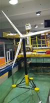 |
Fig. 1 Study of an offshore wind turbine in the experimental channels at EDF Lab Chatou. This small-scale model was used to study the motion of the floater (pitch, roll and yaw) under several sea states, as well as the behavior of the mooring lines. |
2.1.2.1 Focus on nuclear power plants
The design, safe operation (with operating margins), and long-term operation of nuclear reactors (maintenance and even replacement of equipment) depend on understanding and quantifying the physical phenomena at work during their operation, under normal or degraded conditions.
The complexity of these mechanical phenomena (turbulence, rotation, vibration, friction, contact, wear, etc.) and thermal phenomena (heat transfer, phase change, coupling with neutronics, etc.), particularly in the primary and secondary circuits of reactors, often requires them to be isolated in order to understand their effects (separate effects test), at the risk of reducing representativeness (coupled effects). However, several phenomena can be combined and one talk in this case about an “integral effects test”.
From an experimental point of view, two approaches can therefore be distinguished:
In-situ measurement in an operating reactor.
Instrumentation of reduced models representative of more or less isolated components.
In-situ measurement has the advantage of full representativeness, as long as the instrumentation does not disturb the measured phenomenon (intrusiveness). However, this measurement is limited to the data available at a given point in time (pressure, temperature, flow rate, displacement, acceleration, etc.). Examples include measurements during cold and hot tests, which are required for the Regulator to allow the start-up of new reactors, and the permanent instrumentation used to operate the reactor (monitoring) (see Fig. 2). The instrumentation that can be used is therefore constrained by the environment (pressure and temperature resistance of sensors prohibiting the use of on-board electronics in Pressurized Water Reactor conditions, complex access to the area of interest, intrusiveness depending on the number and position of sensors or the routing of sensor cables to the outlet and acquisition bays, etc.), costs (need for reliability and robustness in the case of permanent instrumentation), and time constraints (e.g., cold and hot tests on the critical path of reactor startup).
The use of reduced scale models, operating under more favorable conditions, provides access to more sophisticated instrumentation, enabling a deeper understanding of the phenomena involved. They may also allow us to validate the numerical approaches (code validation). However, the design of these scaled-down models remains a compromise between representativeness (aiming to approximate the scale and conditions of the reactor) and cost (tending to reduce the scale and approximate ambient pressure and temperature conditions to facilitate implementation).
Specifying these scaled-down models requires a PIRT (Phenomena Identification and Ranking Table) analysis, which lists the predominant phenomena to be represented. Dimensional analysis and the Vaschy-Buckingham theorem (n physical independent variables depending on k fundamental units, giving n-k dimensionless variables constructed from the original variables) lead to the identification of dimensionless numbers to be respected between the “model” and the “reactor”. These numbers often illustrate the competition between two or more phenomena, such as, for example, in thermohydraulics:
The Reynolds number (inertial force/viscosity) and Froude number (inertial force/gravity) characterizing the flow regime (turbulent/laminar or forced/mixed/natural convection);
The Prandtl number (velocity diffusion/heat diffusion) or its counterpart for species, the Schmidt number and the Nusselt number (thermal convection/thermal conduction) characterizing the heat exchange between the fluid and a solid wall.
These numbers characterize the similarity with the physics of the reactor and also quantify the deviation (also called distortion) from the latter. They guide the design choices for scale models (prototypes).
With the continuous improvement of the numerical models, these prototype tests now aim at:
Providing validation data for Computational Fluid Dynamics (CFD) codes on well-instrumented case studies with controlled and known boundary conditions (e.g., velocity and temperature profiles, Reynolds stresses, mechanical support conditions, etc.);
Observe and measure real physics, as has been done historically, to confirm or rule out the absence of unexpected phenomena not taken into account in numerical models.
As stated, the representativeness of these scale models remains a limitation. Beyond the exercise of scaling via dimensionless numbers, conservation of regimes or equivalent behaviors, and the choice of pressure and temperature conditions, there remains the risk of non-linearity (intrinsic to flows as described in the Navier-Stokes equations or due to evolving contact conditions with wear, for example). Imperfect knowledge of actual conditions and technical implementation (e.g., manufacturing tolerances not scaled) are two possible sources of this risk. Variations in test parameters (e.g., sensitivity studies to Reynolds number, boundary conditions, geometric details) attempt to mitigate the problem and seek to prove the robustness of the scale model and the results obtained. However, the approach remains limited to the technically accessible domain (e.g., pump flow range, temperature, etc.).
These non-linearities and the associated risk of bifurcation (“cliff effect”) remain the main obstacle to transpose the results from the “model” to the actual operating conditions of the reactor. This therefore justifies on-site tests, despite their intrinsic limitations. In addition, once considered validated on scale models, the confidence in the transposition is reinforced and the numerical models are used under “in-service reactor” conditions.
Despite these stated limitations in terms of representativeness, progress is continually being made on the instrumentation of scale models. In addition to proven and robust but local sensors (gauges, accelerometers, pressure sensors, thermocouples, etc.), current experimenters are seeking to acquire increasingly rich 3D data (ideally 3C, 3 vector field components such as fluid velocity) with high information density, while ideally maintaining fine temporal resolution (in order to capture the dynamics of the phenomena). Thus, non-intrusive methods (optical, acoustic, magnetic, laser, etc.), based on the evolution of wave properties in the media traversed, are deployed to meet the validation needs of 3D numerical models.
For example, time resolved 3D3C PTV measurements have been carried out simultaneously with the dynamic response of a PMMA rod under flow to characterize the Flow Induced Vibration (FIV) of a control rod in a guidance mimicking a CRGA (Control Rod Guide Assembly), equipment submitted to wear caused by the repeated impacts of vibrating rods (see [1]).
Recent Magnetic Resonance Imaging (MRI) measurements have generated 3D fields for the six components of the Reynolds tensor, a sort of “holy grail” for turbulence modeling, with a resolution of around 1 mm3 over more than 1 million points (voxels), elevating these results to “CFD-grade” (see Fig. 3, [2]).
Similarly, for two-phase flows, real-time 3D tracking of the liquid/gas interface remains an experimental challenge, as it does in digital modeling. Nevertheless, with specific tools (e.g., rapid X-ray tomography), which are mainly used in research laboratories, the technical feasibility has already been demonstrated (see Fig. 3, [3]).
These examples highlight the need for the nuclear industry to maintain close collaboration with academia in order to remain at the cutting edge of instrumentation techniques and stay ahead in terms of understanding physics, innovation, and competitiveness.
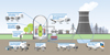 |
Fig. 2 Various sensors and acquisition systems for monitoring operations in nuclear power plants (source : Essais et surveillance des centrales nucléaires | Kistler FR). |
 |
Fig. 3 3D3C (3 Dimensions – 3 Components) fluid velocity measurements by MRI (Magnetic Resonance Imaging) scanner in a 5x5 fuel assembly model at the University of Rostock (left) [2], 3D measurements of void fraction resolved in time by fast X-ray tomography at FZD - Forschung Zentrum Dresden-Rossendorf (right) [3]. |
2.1.3 Numerical modeling
Traditional numerical methods are commonly used in Computational Fluid Dynamics (CFD) to simulate confined flows (reactors and cooling circuits) and free-surface flows (dams, coastal and river power plants, wind turbines). Their use is now common for nuclear and hydraulic safety studies: modeling thermal shocks, stress corrosion, river floods, storm waves, etc.
A wide variety of Reynolds numbers is encountered in a primary circuit of a nuclear power plant for example, going from few thousand O(103) in narrow spaces and with low velocities to tens of millions O(107) in large spaces and/or with high velocities. The low Reynolds numbers (<104) are often encountered in accidental scenarios where the forced convection is very low or even when only natural convection due to buoyancy effect drives the flow. The intermediate Reynolds numbers (104 to 106) are characteristic of the flow though the fuel assemblies or around some obstacles in the lower and upper plenums of nuclear vessels. High Reynolds numbers >106 are found in large pipes such as the cold or the hot legs of the vessels. These high Reynolds numbers are also encountered in atmospheric or fluvial/marine flows and what is stated herein concerning turbulence modeling in nuclear engineering is also valid for these fields. We can split the turbulence modeling techniques into three main approaches (see [4] for more details):
Direct Numerical Simulation (DNS) in which the smallest turbulent length scales are resolved, and no model is introduced in the Navier-Stokes equations. Although much progress has been made in this field, both in the numerical and the high-performance Computing (HPC) fields, the characteristic Reynolds numbers investigated remain low or intermediate and the geometries rather simple. This approach requires very accurate numerical models often developed in in-house codes. In addition to the fact that it allows deep physical understanding of turbulence phenomenon, it can be used for the validation of the next two approaches and feed them with valuable data that can be used to enhance modeling.
Large Eddy Simulation (LES), which allows, if the computational mesh is fine enough with grid spacings giving wave numbers in the inertial zone, resolving the large eddies while modeling the smallest ones. LES concept was launched in the 70’s but has become more popular much later at the end of the 90’s and is still very active today. It can be performed with very advanced numerical techniques allowing to increase the Reynolds number but dealing with rather simple geometries. It is also becoming widely used today in industry using rather simple numerical approaches on very complex geometries. Its current popularity is due to two main reasons: the growth of access to standard HPC facilities and the development of this approach in commercial softwares (STAR-CCM+ and Ansys Fluent for example) and open source finite volume codes and solvers (OpenFoam and Code_Saturne for example) which can handle highly complex geometries using rather simple Sub-Grid Scale viscosity models and often wall functions (so called wall-modeled Large Eddy Simulation).
Reynolds-Averaged Navier–Stokes (RANS) approach, in which the whole turbulent spectrum is modeled using one-point correlations. This approach allows handling of much larger Reynolds numbers than the two previous ones. When the unsteady term is activated and when an unsteadiness is observed, we often talk about “URANS” computations, the “U” standing for unsteady. A problem that is less encountered in LES is the wide variety of RANS turbulence models and of the related constants. The mostly used RANS models are of the family of eddy viscosity models (k-ε, k-ω without going into details) which use the Boussinesq approximation: the deviatoric parts of the Reynolds stress tensor and the mean rate of strain are proportional via the eddy viscosity. The Reynolds stress models or second moment closure models, although more precise in particular for buoyant flows or rotational ones, are still marginally utilized due to numerical instabilities or computing resources costs.
Hybrid RANS/LES models, in particular the non-zonal ones (DES family for Detached Eddy Simulation or SAS for Scale Adaptive Simulation) are more and more used in industrial applications to combine the advantages of RANS (close to the walls where performing LES is not affordable) and LES (when the mesh allows resolving turbulent vortices). While dealing with heat transfer, unfortunately, the widely used models still rely on the concept of the turbulent Prandtl number and solving the turbulent heat-fluxes (2nd order closure for the turbulent heat flux) is still scarce.
Verification and Validation (V&V) is a crucial prerequisite whatever the utilized CFD tool. Before a version release, Code_Saturne (www.code-saturne.org), EDF CFD open-source single-phase flow solver, is validated on hundreds of test-cases, going from elementary ones such as the channel flow to more elaborated ones such as the flow through a diaphragm at high Reynolds numbers. The test-cases are also run every day on few iterations to verify the current version under development.
Numerical modeling now often interacts with experimental methods: pre-dimensioning of a model by simulation, design studies, shape optimization, correction of numerical databases by data assimilation, etc.
CFD is used, for example, for model transposition issues (from experimental conditions to the real-life conditions such as the nuclear reactor one). In fact, dimensionless numbers such as the Reynolds number characterizing the flows in the primary circuit branches can reach 108, and conducting experiments under these conditions is often impossible. When scaling is performed, physical phenomena and their importance are inevitably affected, resulting in distortion. The challenge of scaling is to minimize distortions with respect to the phenomena of interest so that experimental-scale studies are relevant to the industrial system. Advanced scaling methods (H2TS – Hierarchical Two-Tiered Scaling, FSA – Full Scale Analysis and DSS – Distorsion Scaling Synthesis) enable the quantification, at a given scale, of the weight of each phenomenon in the evolution of a quantity of interest using dimensionless quantities named π-groups. Numerical simulation codes are increasingly used to evaluate π-groups, which involve local variables (velocity, temperature, pressure, etc.). The distortion of a phenomenon corresponds to the difference in value of a π-group between industrial and reduced scales. Iterating on the parameters of the reduced scale allows for the optimization of the experiment design, ensuring a reliable reproduction of the desired phenomena. In the example shown in Figure 4, the x and y parameters can be optimized to reproduce natural convection in a nuclear fuel cooling pool. Today, most thermohydraulic experiments in nuclear power have been scaled based on simple laws (for example: Power-to-Volume scaling). Advanced transposition methods have reached a sufficient level of maturity and make it possible to evaluate existing tests retrospectively and to better scale future testing resources. However, the objective quantification of distortions remains at the R&D stage and does not resolve the difficulty of finding a relevant transposition in the case of complex or strongly coupled phenomena.
CFD is also regularly used for the design of experimental devices and also models and complement experimentation when the latter does not allow certain quantities to be obtained.
More recently, AI has also been used in electricity production, for example for safety purposes: flood warning systems benefit greatly from deep learning (e.g. Fig. 5); programming itself is now aided by AI thanks to coding agents.
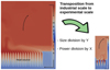 |
Fig. 4 Example of transposition from industrial to experimental scale for natural convection in a pool. EDF R&D, MFEE (Courtesy of P. Dené and A. Richard). |
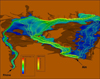 |
Fig. 5 Simulation of a hypothetical dam breach on the Rhône River (EDF). The hypothetical dam failure is supposed to occur on the river “Ain”. The colors represent the water levels and the lines are streamlines colored by the velocity magnitude. |
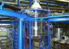 |
Fig. 6 Photograph of a hydraulic model of a reactor vessel lower internals (scale ∼1/5) upstream of the core, typical velocity in feeding pipes: 6 m/s. FRAMATOME Technical Center. |
 |
Fig. 7 Study of pressurized thermal shock on a reactor pressure vessel, Dept. MFEE, EDF R&D. |
2.1.3.1 Numerical modeling in fluid mechanics for nuclear reactor vessel
The thermohydraulic design of large components such as the reactor vessel—the only non-replaceable element at the heart of the nuclear boiler—plays a fundamental role. The flow of pressurized water must be controlled to ensure proper cooling of the core and preservation of the fuel cladding, which constitutes the first safety barrier.
While the validation of the hydraulic design of the vessel in older French reactors (900 MWe, 1300 MWe, and 1450 MWe) was based exclusively on experimental results obtained from small-scale hydraulic models, the validation of new reactors is based on a dual approach combining numerical and experimental methods.
Model tests (Figs. 6 and 7) provide essential information but remain costly, can be biased due to implementation limitations, and are sometimes difficult to transpose to the scale and operating conditions of the reactor (particularly fluid pressure and temperature).
Thus, with the rapid development of computing capabilities (HPC), combined with increasingly advanced physical and mathematical models, detailed numerical simulation of 3D flows can complement the experimental approach in justifying a design.
The strong synergy mentioned above between experimental and numerical fluid mechanics, particularly in the justification of a design, naturally relies on rigorous physical validation of the numerical models used (Fig. 8). Physical validation of numerical tools is therefore a prerequisite for the acceptance of any hydraulic design based on CFD. The aim is to demonstrate the ability of the codes to accurately reproduce the physical phenomena identified as predominant in PIRT (Phenomena Identification and Ranking Table) analyses.
This validation, known as “integral” validation, involves several combined physical phenomena and is based on the code qualification file. The latter includes, among other things, validation cases with separate effects—analytical or semi-empirical—guaranteeing the consistency of data sets (discretization, models, algorithms, etc.), in accordance with the requirements of the Regulator, particularly those of ASNR Guide 28 [5].
The combination of advanced physical and numerical models, coupled with a systematic assessment of uncertainties, has enabled CFD to establish itself as a valuable predictive and design tool in the nuclear field.
At the same time, the development of experimental methods, such as 3D particle image velocimetry (PIV), offers increasingly refined validation of CFD tools. These approaches are converging towards a level of maturity sufficient for full integration into safety demonstration, ensuring accurate modeling of hydraulic facilities while continuously improving their performance.
Passive technologies are featured in many modern reactor designs and almost systematically in Small Modular Reactor (SMR) designs. Their main goal is to simplify the overall architecture of these reactors and improve safety, notably by providing greater autonomy in cooling systems and enhancing robustness against extreme scenarios (loss of electrical power or cooling chain failure). The Passive Residual Heat Removal System (PRHS) or Safety Condenser (SACO) and the Passive Containment Cooling System (PCCS) or Containment Wall Condenser (CWC) are among the most used technologies for pressurized water reactors. These systems transfer energy via naturally circulating two-phase thermosiphons between a hot source and a cold source located at a higher elevation, driven by density differences. They can operate in a closed loop, using heat transfer mechanisms such as boiling and condensation, with the main advantage of leveraging the high latent heat of phase change compared to sensible heat. These systems provide autonomy during accident scenarios and must be sized to meet the required power extraction levels and mission duration before active intervention systems are needed. The POOL-LOOP facility (Fig. 9) is a stainless-steel pool operating at atmospheric pressure, designed for the Spent Fuel Storage Pool application. This facility is primarily dedicated to characterizing the use of Immersed Heat Exchanger (IHX) inside a pool, where a natural convection flow is expected to passively transfer heat from the hot source (the spent fuel assemblies, represented by electrical heaters) to the IHX, which functions as the cold source. The facility dimensions are 7 meters in height, 2.5 meters in length, and 1.6 meters in width. The primary objective is to demonstrate the establishment of a natural convection loop within the pool, including the IHX, and to assess the IHX's performance in passively dissipating heat. The secondary objective is to validate local Computational Fluid Dynamics models at the experimental scale of POOL-LOOP, with the intention of transposing these models to an industrial scale.
Fine computation, also called “high-fidelity” simulations (DNS or wall-resolved LES) are today affordable at reasonable Reynolds numbers. In addition to flow physics understanding, these approaches allow to compute advanced statistics allowing validating and improving RANS or hybrid RANS/LES models. Accurate flow measurement in industrial piping systems is critical for numerous applications, including Pressurized Water Reactor (PWR) nuclear power plants. Orifice flow meters [6,7] are widely used for their robustness and passive operation, providing precise flow rate measurements—provided that specific requirements are met, such as proper pipe geometry and fully developed inlet/outlet flow conditions. These meters operate based on the pressure drop caused by fluid acceleration through the orifice, converting static pressure into dynamic pressure. Standards like ISO 5167, which are grounded in extensive experimental data, define the conditions under which empirical correlations—such as the Reader-Harris/Gallagher equation—can be used to predict the discharge coefficient (Cd). The flow through an orifice plate exhibits complex behavior, including acceleration, shear layers, flow separation, and downstream reattachment. A recirculation zone forms downstream of the plate, characterized by high turbulence intensity (Fig. 10). This complexity poses significant challenges for Reynolds-Averaged Navier-Stokes turbulence models, whether using first-order or second-order closure approaches. While RANS models can predict the discharge coefficient accurately under ideal conditions, they often fail to capture detailed flow features such as the recirculation length. Large Eddy Simulation, although not yet viable for routine industrial use due to computational cost, offers deeper insight into flow structures at moderate Reynolds numbers (up to Re = 105). Note that the LES performed in [6] has been performed in 2016; a factor of 4 in the Reynolds number has been gained within roughly 10 years.
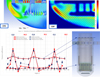 |
Fig. 8 Physical qualitative validation of a numerical model – Example of elements of qualitative validation (top, reproduction of a recirculation zone at the bottom of a plenum) and quantitative validation (bottom, comparison of pressure profiles in the annular space of a vessel – so-called downcomer) – Framatome. |
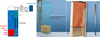 |
Fig. 9 Pool Loop facility. (Right) CFD pre-tests. |
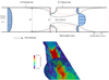 |
Fig. 10 (Top) Orifice Flow meter general configuration, (Bottom) instantaneous velocity magnitude using wall-resolved LES at Re = 105 (computation performed on several thousands of cores on Selena supercomputer in 2025). EDF R&D, MFEE Dept. Courtesy of P. Borel and S. Benhamadouche. |
2.2 Solid mechanics
2.2.1 Material behavior
2.2.1.1 Concrete
The use of concrete as a construction material is widespread at EDF, whether in nuclear power plants (containment buildings, cooling towers, reactor buildings, nuclear waste storage facilities, etc.) or dams. With a view to ensuring the long-term durability of these structures, four major areas relating to the behavior of concrete are the subject of intensive study, underpinned by a balanced compromise between physical realism and controlled usability of the models:
Water transfer through connected pores or possible cracks, due to its consequences in terms of local overpressure (dams), loss of watertightness (enclosures), etc.
Delayed deformation, an important factor in the aging of structures. This includes both shrinkage and creep phenomena.
Physicochemical reactions of internal swelling and their impact in terms of local degradation of mechanical properties and overstressing due to blocked deformation, particularly for dams.
Damage to concrete under excessive loading, which accounts for the appearance of microcracks.
These areas are most often examined from a phenomenological perspective, based on numerous analytical test campaigns on laboratory specimens and a few full-scale tests on large models, the largest being a 1/3 scale containment building (Fig. 11). To a lesser extent, work based on microstructural data and scaling methods complements the modeling, for example to access the properties of in-situ concrete.
Finally, construction techniques often combine concrete with steel, whether in the form of reinforcement, prestressing cables, or sheet metal. The latter can play a structural role, as in steel-concrete constructions (modular structures), or a non-structural role, as in liners that provide a waterproofing function. The study of the interactions between these metal components and the surrounding concrete also plays a crucial role in characterizing the properties of this composite material.
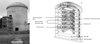 |
Fig. 11 Outer containment wall of the VERCORS mock-up and sectional schematic view : 1:3 scaled mock-up enabling accelerated ageing by a factor of 9. |
2.2.1.2 Metals
Given their large size and the performance required for energy transfer and conversion, metal structures and systems are ubiquitous in power generation facilities. At these scales, damage control issues are paramount to ensuring maintenance and operability.
In the field of nuclear power generation, there is the additional issue of risk, which is covered, among other things, by high design and manufacturing requirements: the primary circuit and the auxiliary lines connected to it constitute the second barrier for containing fission products after the fissile fuel assemblies. At temperatures (above 300°C) and under pressure, demonstrating its integrity is a prerequisite for all possible operating situations, from nominal operation to the least likely accident scenarios.
The very high level of requirements demands in-depth knowledge of materials: their behavior under the conditions of use encountered (including under irradiation) as well as their failure modes and modes of degradation over time. For metal components, this involves fatigue, fracture (in ductile and quasi-brittle domains), corrosion, creep (at temperature or under irradiation), not to mention the possible interactions between these different failure modes and possible changes over time.
These material behaviors and failure modes are mainly examined through tests on test specimens, from which characteristics are extracted to feed into phenomenological models. However, this work is also supplemented by small-scale experimental and theoretical studies (grain scale and below) on the one hand, and by structure-scale tests and analyses on the other, in order to address issues of transferability from one scale to another and representativeness regarding actual behavior and stresses.
2.2.1.3 Welding assembly
High-temperature processes at the end of manufacturing govern the main properties of products assembled by welding at the end of manufacturing: heat treatments, welding, etc.
The materials used in the nuclear industry, particularly for pressurized water reactors and second containment barrier equipment (main primary circuit), are nickel-based alloys, austenitic stainless steels, and low-alloy steels for pressure vessels coated internally with stainless steels whose required characteristics are clearly specified (construction and operating codes—RCCM and RSEM). Components assembled without welding (base metal) meet manufacturing requirements that enable the expected characteristics to be achieved (minimum yield strength, resilience, toughness, etc.). For welding, additional tests are required to characterize the base metal/deposited metal bond and to ensure the absence of defects by Non Destructive Testing. However, additional precautions may be required based on an analysis of the operating experience of these specific areas, which are essential for ensuring the mechanical continuity and tightness of Pressure Equipment.
Welded assemblies may have a residual state that distinguishes them from the base metal. The characterization of assemblies during acceptance testing is therefore subject to additional specifications to characterize the welds in relation to the control of the process used and the choice of filler materials. In addition, the residual stresses induced by welding are relieved by dedicated heat treatment, often local due to the size of the objects concerned. Here too, a multidisciplinary approach makes it possible to optimize the design of the treatment through fluid mechanics and thermal simulation, to estimate the residual stresses at the end of the treatment through thermomechanical simulation, while materials science makes it possible to set the temperature limits and holding times to be respected in order to guarantee the correct behavior of the assembly in relation to the base metal.
Being able to determine the residual manufacturing condition of welds is an important factor in resolving issues at the interface between materials and mechanics, with the aim of anticipating and controlling unforeseen events that occur in the operating fleet. In this regard, the issue of stress corrosion cracking in the Primary Circuit's auxiliary lines faced by EDF, and the studies carried out by EDF to resolve it, clearly demonstrated that the risk of SCC occurring in particular line configurations and operating conditions depends, among other things, on the welding method used. Thus, the expertise gained from feedback, numerical welding simulation, and the implementation of an extensive program of welded assembly models have contributed to demonstrating an understanding of this issue.
In this context, numerical welding simulation, commonly referred to as NWS, is a recognized approach (ISO standard, widely used for certain applications) which, when integrated into mechanical calculation chains, enables best-estimate analyses by providing a new perspective on the treatment of welding-related issues, both in terms of the choice of assembly, repair, or mitigation processes and in terms of the consideration of this residual state (stress and sensitization due to work hardening) for SCC crack propagation estimates.
2.2.2 Experimental approach
Experimentation, on different scales, remains an essential factor in dimensioning, as does the justification of components over the envisaged operating periods. Where possible, these tests are carried out on materials and under representative test conditions.
Previously separate from modeling, today's tests are closely linked to it through measurement methods, data analysis protocols, and interpretations designed to be coupled with models and simulations.
While test specimens are the norm for material characterization tests, mock-ups or quasi-components remain important and are used for reasons of representativeness, model and criteria transferability, or simply for experimental demonstration to support a justification dossier (Fig. 12).
 |
Fig. 12 Failure of a full-scale welded joint in the quasi-brittle range, in the presence of residual welding stresses. |
2.2.3 Structural analysis
At the structural level, new disciplines are being mobilized to complement those already mentioned for material modeling. They are part of an approach to informed decision-making through numerical simulation of the behavior of components and structures. In this industrial context, they aim to meet robust objectives to guarantee results, reliability and therefore credibility of these results, and finally performance to remain compatible with design deadline constraints.
The first disciplinary component concerns the modeling of structures that are slender in one direction (bars, cables, beams) or two (plates, shells) (Fig. 13). The objective here is to take advantage of this slenderness to reduce study times and facilitate the interpretation of results. Although this is a long-standing topic, its implementation in a highly non-linear context, due to the materials and the intensity of the loads, remains highly relevant, as evidenced by a steady stream of academic publications.
A second important topic concerns damage modeling, up to fracture and cracking. An initial approach, mainly reserved for metallic materials, consists of focusing on the conditions for initiating or triggering a crack, under cyclic (fatigue) or monotonic (fracture mechanics) loading, particularly in the presence of plasticity (Fig. 14). A second, more refined approach examines the evolution of local fields under the effect of mechanical degradation of materials. This problem of structural damage has specific characteristics that distinguish it from more conventional nonlinearities, justifying a significant amount of academic work (non-local models and/or phase fields). Added to this is often the issue of physical and numerical instabilities, which require special attention and numerical techniques.
Furthermore, many studies carried out at EDF require consideration of the conditions of contact between parts (Fig. 15), a phenomenon whose high degree of non-linearity can call into question the robustness of simulations when high standards are set for the quality (and therefore credibility) of the results. Added to this is the potential need to take into account friction in contact areas, which further weakens the robustness of the calculation, and even the modeling of wear (tribology). Other interface behaviors are also being studied, particularly with a view to modeling cracking (cohesive zone models).
Finally, certain applications require consideration of the dynamic behavior of structures, either from the perspective of analyzing vibrational response (modal analysis) or for describing transient regimes (impacts, earthquakes, etc.). In this regard, the interaction between structures and the ground (soil/structure interaction) and the modeling of the surrounding soil, for example at the scale of a nuclear site, are also the subject of particular attention (see focus below).
These various mechanical disciplines may also involve questions relating to applied mathematics, whether it be the examination of the fundamental properties of structural calculation problems or the numerical implementation of mechanical models. A typical example is the study of variational formulations to ensure well-posed problems, a guarantee of robustness, while preserving a regularity of solutions in line with mechanical intuition. This then leads, in the numerical field, to issues of temporal (time schemes in dynamics) and spatial (finite, hybrid, mixed elements, etc.) discretization. In addition, linear algebra issues are raised by the resolution of discretized problems, most often large ones, which raises performance issues. In another vein, branches of mathematics such as optimization, data assimilation, and Bayesian approaches make it possible to link experimentation and simulation. Finally, examining the propagation of uncertainties lends additional credibility to the results obtained, taking into account the vagaries of stresses and the variability of mechanical properties.
Generally speaking, applying these different mechanical and mathematical disciplines leads to the development of numerical models that underpin structural studies. EDF has chosen to capitalize on these models in a solid mechanics calculation code (Code_Aster and its Salomé-Méca platform) developed in-house and made available to the mechanical engineering community as open source. This choice was dictated by considerations of model control, the freedom to implement innovative choices in response to specific problems, and engineering access to these R&D innovations, considerations to which is now added the need for sovereignty in a tense geostrategic context.
As a result, the in-house development of the Code_Aster calculation code also involves computer science disciplines. This begins with software engineering, as the code capitalizes on 35 years of R&D work through 1.5 million lines of multi-language source code. Verification and validation concepts, including code coverage measurements, ensure product quality, a formal requirement of the French Nuclear Safety Regulator (ASNR). Finally, the scale of the problems addressed requires the use of massively parallel computing (HPC) strategies, in conjunction with the architecture of the high-performance machines used (Fig. 16), and raises questions about the propagation of rounding errors, which are all the more significant in this HPC context.
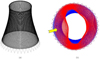 |
Fig. 13 Finite element analysis of an air cooler (a) mesh (b) effect of wind (displacement). |
 |
Fig. 14 Propagation of a semi-elliptical defect in a pipe under 4-point bending. Comparison of test and calculation [8]. |
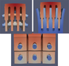 |
Fig. 15 Low pressure body of a nuclear power plant turbine: wing/body pins simulation. |
 |
Fig. 16 SELENA supercomputer (EDF & FRAMATOME – commissioned in 2025). With CRONOS (commissioned in 2021) and SELENA, the EDF Group now has more than 15 petaflops of computing capacity. |
2.2.3.1 Focus on dynamic analyses in the field of nuclear power generation
The study of dynamic phenomena in the nuclear industry is necessary:
To prevent premature wear and tear, or even fatigue failure of components, due to excessive vibration stress over too long a period of time.
To prevent damage to equipment during transients involving rapid changes of state (valve openings, isolation valve closures, etc.).
To ensure the safety of the facility during internal accidents (pipe rupture, explosion, falling loads during handling, etc.) or external accidents (earthquake, tornado, plane crash, etc.).
In all these cases, the same dynamic equations can be solved to determine the levels of stress, strain, deformation, wear, or any other relevant variable in order to enable the appropriate dimensioning of structures, systems, and components and, where necessary, the experimental qualification of the equipment they carry (typically on vibration tables).
Ultimately, the aim is to give the systems and components the necessary dimensions to meet mechanical performance criteria under the loads considered and to ensure that the onboard equipment is capable of performing its function, either during or after dynamic stress.
The codes used for the analyses are commercial or proprietary codes that solve the equations of dynamics on a modal or physical basis, either by explicit time integration algorithms (short loads, shocks, explosions, etc.) or implicit (vibration or earthquake with non-linearities), or by calculations in the frequency domain (vibrations of linear systems, load transfer), or by modal-spectral or pseudo-static analyses (particularly in earthquakes) aimed at obtaining only the maximum response of a structure to the load in question.
In this process, two fundamental difficulties stand in the way of the analyst. The first is knowledge of the actual loads that will be exerted on the components in the reality of the scenarios studied, and the second is knowledge of the actual dynamic behavior of the component, in particular its boundary conditions (the interfaces between the component and its environment) and its damping (the component's ability to dissipate the energy brought to it by the load). These two difficulties, as well as the practices put in place to address them, are discussed in the following paragraphs.
The dynamic loads to which components in a nuclear facility may be subjected can, in certain specific cases, be known in a deterministic manner, for example, the impact velocity resulting from a drop height for a suspended load. In most cases, however, the uncertainties or variations are such that the loads can only be defined probabilistically.
For vibratory stresses, a probabilistic approach is standard industry practice. Loads are defined by power spectral densities, for example pressure forces on a component, and the response is itself expressed in terms of mean value and associated variability (typically Root Mean Square value and peak factor). The great difficulty lies in the very definition of stress.
The operation of a nuclear reactor requires the movement of fluids by mechanical pumps that must ensure the required flow rates and pressures. As a result, a variety of excitation is transmitted to the systems and components:
Solid excitations, particularly due to the effects of imbalance caused by the inevitably imperfect balancing of the rotor relative to the stator, which are transmitted through the system via the metal and civil engineering structures.
Turbulent excitation, especially downstream of geometric discontinuities: reduction or increase in the cross-sectional area of a pipe or flow channel, jet burst at the inlet of a reactor vessel, passage of fuel assembly grids, etc.
Acoustic excitations in the form of compression waves in the fluid, generating dynamic stresses on the systems, particularly at each change in the direction of the fluid.
Finally, excitations due to fluid-elastic phenomena, where pressure variations in the fluid can themselves be reinforced by the vibratory movements of the structure in response to these pressure variations. In some cases, such as in heat exchanger tube bundles under transverse flow or slender components in an axial flow channel, this type of vibration can lead to rapid component failure.
Direct measurement of pressure variations in the fluid is not only difficult to implement due to the high pressures and temperatures in reactor circuits and the very high stresses on any nuclear reactor building penetration, but also impossible to generalize: the measurement is always at a single point, whereas the pressure field is three-dimensional and its effect on the structure is the integral of these local effects over the entire wetted surface. The nuclear industry therefore relies on experimental campaigns on models of structures under fluid flow to either produce equivalent loads, generally dimensionless, applicable in design, or to qualify numerical models of fluid flow, or to observe in the laboratory and on models, possibly on a reduced scale, the vibratory phenomena expected on the installation.
For external aggressions of natural origin, foremost among which is earthquakes, the load is known only probabilistically, with a high degree of associated uncertainty. Seismic risk, for example, is assessed by geologists on the basis of seismic zoning extending several hundred kilometers around the facility and listing known potential sources (active or inactive faults), the seismic history of the site, as documented in regional archives (historical seismicity), as measured by accelerometer networks set up in recent decades (instrumental seismicity), and as inferred from observations of discontinuities in geological layers (paleoseismicity). In cases where there are insufficient geological, historical, and instrumental observations, the seismicity of other regions considered geologically similar and for which more data is available is used as a reference.
On this basis, different seismic scenarios are developed, leading to an estimate of the seismic hazard at the facility site, which naturally takes the form of a probability: response spectra, expressed as amplitude as a function of frequency, with a certain probability of being exceeded over a given period (typically 10,000 years or 100,000 years). For the design of the facility, a single spectrum is selected, representing a very low probability of being exceeded over a period much longer than the lifetime of the facility. This spectrum is then used as a single, deterministic input for the seismic design of the facility.
This deterministic approach, which is the benchmark for the seismic design of the facility, has nevertheless been supplemented for several years by a probabilistic approach in which probabilistic spectra are considered, and the response of structures, systems, and components is also probabilized: median values and associated uncertainties are used instead of the envelope and penalizing values typical of a design. The results of these analyses are the probability of failure of a component or system as a function of the seismic level applied to it (fragility curve of the component or system) or the annual probability of occurrence of an accident at the level of the entire facility, the designer's objective being, of course, to minimize this value.
Finally, for industrial or human-induced hazards, as well as for transients induced by rapid state changes, the analysis is purely deterministic. Accident scenarios are established in such a way as to reasonably cover all possibilities. These scenarios are then applied to the models of structures, systems, and components, and the most penalizing of them are retained for the design of these structures, systems, and components, as well as for the qualification of the equipment they carry.
In principle, the dynamic response of a structure (or system, or component) to an excitation is essentially dependent on the ability of this excitation to excite or not excite the natural modes of the structure, the distances between the natural frequencies of the structure and the frequency range(s) of the excitation, as well as the ability of the structure to dissipate the energy applied to it.
Knowledge of the excitation capacity is closely linked to knowledge of the loading, as mentioned above. For fluid excitation, it is the admittance between the applied force field and the modal deformation that expresses this capacity. For seismic excitation, it is the participation coefficient or the participating mass of the mode that expresses its excitability by the stress.
Knowledge of the natural frequencies of the structure, if it can be considered linear, i.e., if its mass and stiffness characteristics do not vary with the amplitude of deformation during its dynamic response or with time, is fairly simple to obtain numerically if its boundary conditions are known. However, knowing these boundary conditions is a real challenge in practice because:
Many metal structures are assembled using bolted connections and fixed to civil engineering structures using anchors. Depending on the design of these connections, they are similar to either fixed or ball-and-socket joints. In reality, their stiffness is more complex, often falling between these two ideal theoretical cases. In addition, the dynamic characteristics of some connections depend on the load applied to them.
Components and systems are fixed to civil engineering structures by supports designed to provide certain types of connections: fixed point, slide, bearing, or other. These supports have a certain rigidity, the interfaces connecting these supports to the equipment (ears, collars, caps, etc.) also have a certain rigidity and, in the case of massive components, the civil engineering to which the supports are anchored may also have significant flexibility.
Non-linearities in the supports exist for many types of equipment: variation in stiffness depending on the loads applied (typically in shock absorbers and self-locking devices, etc.), play in slides and ball joints making it difficult to assess their vibratory behavior (in tie rods, struts, etc.), play in the passage of tubes between spacer plates or between spacer plates and support collars (inside steam generators, instrumentation, etc.).
The use of simple analysis methods therefore requires a simplification of the boundary conditions compared to reality and the “linearization” of most structures, systems, and components during dynamic analyses. For transient and accident analyses, this difficulty can be overcome by choosing conservative (penalizing) models or by studying different cases, selected in such a way as to reasonably limit the different possible behaviors. For vibration studies, on the other hand, a precise description of the structure's behavior is necessary. In this case, an approach based on on-site measurements or laboratory tests can be used to feed the models.
For systems and components whose dynamic response induces sliding, impacts between structures, or tilting (typically handling equipment, storage racks, etc.), the very notion of natural frequency may no longer be appropriate. In these cases, too, the parameters defining the interface conditions are paramount:
Coefficients of friction.
Type of surface coming into contact (location and spread of contact areas).
Deformability of contact areas, where applicable, contact “stiffness” (stops, etc.).
These parameters are defined either conservatively, in order to limit the possibilities, or through on-site testing and measurements.
Once the boundary conditions and interface conditions of a model have been established, the main remaining difficulty is the estimation and modeling of damping. While some energy dissipation can be represented explicitly in a numerical model (energy dissipated by friction, plasticization, viscous dampers), it is generally impossible to represent all of them in detail. In particular, local plasticization, friction within bolted connections or between the structure under study and its immediate environment, interactions with small, supported components, and energy radiated outside the model are almost never represented.
On-site measurements, either under operational vibrations (due to reactor operation), imposed vibrations (vibration pots), or impact hammers, sometimes make it possible to recover damping values in situ to feed into vibration analyses. Site experience shows that these values can vary greatly between equipment that is relatively similar at first glance. This is often due to details in the design or installation of the interfaces. It is also common to observe a dependence of damping on the amplitude of the applied load, all other things being equal, reflecting the fact that a higher load tends to activate more local nonlinearities.
For accident scenario analyses, the damping values to be applied are described in the codes and design standards or in national regulations. This is advantageous in that it is generally not possible to test structures, systems, and components of very large dimensions at the levels of deformation they will reach during such accidents. In specific cases, however, tests on models, up to 1:1 scale, have been carried out on vibration tables to determine realistic damping levels for certain strategic components, particularly under seismic loading (fuel assemblies, steams generators internals, etc.).
Finally, in certain cases of submerged structures, it is possible to estimate the damping that can be provided by the presence of fluid using couplings or chains between structural calculation codes and fluid calculation codes. The implementation of effective coupling between codes also makes it possible, for problems of vibration induced by fluid flow to explicitly represent the phenomena of turbulent, acoustic, and elastic fluid excitation on the structure and to take into account the feedback of the structure's movement on the fluid flow. This aspect is the subject of intensive R&D to bring the tools to a level suitable for industrial use.
Once the damping value(s) to be applied to the model are known, the final challenge is to effectively implement them in the analysis. Starting with modal damping models (modal-based resolution), hysteretic models (frequency domain resolution), or Rayleigh damping models (usually for time domain resolution), which are standard in all industries, variants of damping models are used on a case-by-case basis to improve the consistency of the results with the target values or to eliminate the undesirable side effects of certain damping models (e.g., the damping of rigid body modes when a Rayleigh model is used).
2.3 Fluid-structure interactions
Scientific literature offers several classifications of fluid-structure interaction phenomena. For illustrative purposes, we propose here one that is adapted to energy production activities. It does not claim to be exhaustive; for example, activities related to installation noise are not included. Depending on the nature of the mechanism stressing the structures and the physical quantity of interest, several categories can be distinguished.
Flow-induced vibrations (FIV) constitute a separate field within industrial studies involving fluid-structure interactions. They originate from turbulent or even two-phase flows present in certain components. These flows generate random pressure fluctuations that act on structures and cause them to vibrate. Studies are often undertaken following the observation of unexpected vibrations at production sites and require an analysis of measurements combined with a model of understanding in order to diagnose the condition of the installation and, if necessary, propose remedial measures.
Accident studies, in particular seismic calculations for installations and Loss of Coolant Accident (LOCA) studies, are hypothetical accident scenarios provided for in safety studies, which require the response of the structure to a transient stress to be determined by calculation. In the case of seismic studies, this involves a displacement imposed simultaneously on all the support points of the facility. In the case of LOCA, it involves a depressurization wave that propagates within the primary circuit. The dynamic response of the facility to these stresses generates stresses, the safety of which must be guaranteed.
The vibrations of rotating machines, particularly centrifugal pumps, include a portion of random vibrations under flow, as well as a portion of harmonic vibrations at the pump's rotation frequency and its multiples, or even its sub-multiples.
The disciplines of solid mechanics and fluid mechanics are necessary to study these phenomena. They also have specific characteristics in terms of taking into account the interactions between fluid and solid, as well as the variety of phenomena observed, which make them a discipline in their own right. By way of illustration, the study of the vibrational response of a structure to turbulent flow can be carried out on the basis of a representation of the loading according to the independence hypothesis, i.e., assuming that the turbulent flow is only marginally disturbed by the movements of the structure and can be studied as if the structure were fixed. It is then possible to represent the structural vibration response by adding a simplified fluid model, for example by introducing added masses or representing it with a potential acoustic model. In this case, the fluid is represented very differently at the local scale where the turbulent forces are produced and at the larger scale of the structure.
A specific skill associated with all of these activities concerns the performance of measurements on industrial sites, whether to validate models or to record vibrations and fluctuating pressures during operation. This is a highly specialized experimental skill, requiring the ability to adapt the measurement system in real time to the conditions of the installation, including in the event of unexpected behavior. This skill can even enable real-time “modal expansion” to be performed, allowing the best possible estimate of deformation during operation and the most accurate state-of-the-art refinement of the level of stress it undergoes.
3 An integrated approach of the lifecycle of a component
As mentioned above, the integrated approach to a component's lifecycle makes it possible to take into account, from the design stage onwards, all the stresses, whatever their nature, to which it will be subjected during its lifetime. A non-exhaustive series of examples is used to describe how mechanical engineering disciplines are involved in the major stages of a component's lifecycle, from its design to its end of life, including the crucial stage of its manufacture.
3.1 Fluid mechanics
3.1.1 Thermohydraulic studies for extending the operating life of nuclear reactors (long term operation or LTO)
One of the factors limiting the lifespan of nuclear reactors is related to thermal loads induced by normal or incidental reactor operation, mainly due to two phenomena:
Fatigue. Thermal transients associated with the cooling and reheating cycles of components due to normal operation (power variations) or incidental operation (e.g., injection of cold fluid into a hot reactor) generate mechanical stresses in the equipment. These stresses alternate between heating and cooling, creating a cycle that gradually damages the equipment.
Brittle failure. Materials may have defects, either from the manufacturing process or due to progressive irradiation. It is necessary to demonstrate that the thermal stresses associated with thermal transients during the life of the unit do not present a risk of equipment brittle failure.
The usual practice is to describe the various thermal transients experienced by the equipment either by simplified methods (engineering analysis based on an analysis of the unit's operation) or by simulations performed using “system” codes, i.e., codes that represent the entire unit as a set of pipes and volumes.
These approaches are generally quite limited because they do not take into account mixing zones, which have essentially 3D flows, nor, in most cases, the inertia of structures, which tends to smooth out thermal transients.
In recent years, methods have emerged that allow for the integration of detailed 3D analyses. These methods generally represent the three-dimensional flows present in the equipment in detail and use the overall behavior of the unit modeled at the system level as a boundary condition. It is therefore, in a way, a complementary refinement of the analysis at specific locations.
The advantages of these analyses are the following:
They take into account the three-dimensional nature of the flows. This avoids “piston” type flows that propagate sudden temperature change fronts, in favor of a more realistic and often smoother representation of temperature variations.
It takes into account the locality of temperature gradients. A more detailed representation of actual temperature fields avoids discontinuity effects at the interfaces between different study areas, where temperature changes are often uncorrelated in so-called “envelope” analyses.
Consideration of combined heat transfer and the inertia effect of structures on loads. The idea behind this phenomenon is simple: if a structure is cooled with cold fluid that is in motion, the downstream areas will see water that has warmed up on contact with the metal in the upstream areas. This dampens the cooling in the downstream areas.
Taking these phenomena into account, provided that the codes are correctly validated (see Sect. 2.1.3), makes it possible to limit thermal loads on structures based on a more detailed consideration of the physics of flows, which contributes to extending the service life of units.
3.1.2 Core studies
Among the components of power plants that are the subject of research in thermohydraulics and fluid-structure interaction, it is impossible not to mention the core of nuclear reactors. In PWR (Pressurized Water Reactor) technology, fuel assemblies consist of bundles of fuel rods several meters high, held in place by grids, which provide mechanical support and also promote mixing to facilitate heat exchange. These assemblies are arranged in close proximity to each other in a core and undergo mainly vertical flow, as well as partially transverse flow due to the shape of the incoming flow layer, as illustrated in the Figure 17. Predicting the distribution of these flows and their effects on the assemblies is an ongoing research topic, one of the difficulties being the practical impossibility of creating a fully representative study model that respects the number of assemblies present in the core or the Reynolds number.
On a slightly larger scale, vibrations in large components of a primary circuit continue to be the subject of research. Figure 18 shows a design study for a four-jet impact model, which simplifies the geometry of a PWR vessel. The model will be equipped with pressure sensors to reconstruct the temporal and spatial loading of an inner cylinder, similar to the shell of a core.
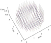 |
Fig. 17 Opening of fuel assemblies in the reactor core under the effect of a hump-shaped incoming wave (amplitudes adjusted for visualization) – EDF. |
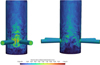 |
Fig. 18 CFD using wall-modeled Large Eddy Simulation to assist in the design of a reactor core model with a study of the turbulent loading exerted by four lateral jets and a vertical evacuation (courtesy of O. Tazi Labzour). |
3.1.2.1 Corium in severe accident scenarios
Safety studies related to severe accident (SA) scenarios often involve assessing phenomena related to corium, a material formed from the core melting which can reach temperatures of 3000 K, during the different phases of a severe accident (core degradation, in-vessel, ex-vessel, and long-term management). The development of phenomena-specific codes, or the use of general-purpose codes, which can model these phenomena at different scales are important to correctly assess the risk of containment failure associated with a SA scenario, its long-term management, and mitigation strategies for operating or future nuclear power plants.
Two examples of corium-related phenomena are described here: corium spreading, and steam explosions (SE) resulting from corium-water interactions:
Corium spreading is generally studied with specific, 1D/2D, shallow water equations codes. One of the main current challenges is the coupling of spreading with solidification, especially the mechanical effects of the top crust (in case of underwater, but also dry spreading). Future research may therefore focus on improving associated models (or testing alternate tools, e.g., Method of Particular Solution codes) and experimental validation databases for underwater spreading.
Steam explosion (SE) is generally studied using specific multiphase 1D/2D/3D CFD codes. Among several challenges are the modelling of some of its key mechanisms, such as the fragmentation of very high temperature corium drops by high speed and pressure (∼ 10 - 1000 bars) water flows, with solidification and oxidation, and the assessment of SE mitigation using water additives. Future research may therefore focus on improving the modelling of SE key mechanisms using both CFD (e.g., CFD codes with adaptative mesh refinement such as Basilisk) and experiments (no available data for single-drop fragmentation in reactor conditions), and testing new mitigation strategies (surfactants, super-absorbing polymers, etc . . .).
Finally, a common challenge when modelling corium-related phenomena is the assessment of the corium physical properties and rheology due to its complex composition, which is a mixture of oxidic (UO2, ZrO2), metallic (U, Zr, steel), and concrete elements.
3.1.2.2 Steam turbines
Approximately 70% of the world’s electricity is generated by thermal power plants relying on steam turbines to convert the heat into mechanical energy. Their efficiency is affected by several types of losses, which come mainly from aerodynamic phenomena, leakages and wetness. High temperatures and pressures, and water droplets present in condensing turbines cause material degradation by creep, fatigue, corrosion and erosion, thus reducing turbine’s life and increasing the maintenance costs. The key challenges in managing steam turbine performance and aerothermodynamic behavior are the prediction of complex multiphase phenomena in rotating machineries:
Unsteady flows from rotor-stator blade rows interactions, separations, recirculations, turbulence,
Wetness effects such as nucleation and growth of small water droplets, deposition on blades, water films formation, atomization of large droplets, impacts on blades.
Accurate modeling of steam flow and turbine performance prediction require using and combining different types of steady and unsteady rotor-stator models, mono- and poly-dispersed condensation models, and additional models describing other wetness features. High-quality numerical models and measurement techniques are widely used by the scientific and industrial communities for rotating flows. Wetness modeling still needs improvement: increased accuracy for all features, covering a larger range of configurations and flow regimes, considering interactions between them, leading to a global representation of the complete chain of phenomena. Today’s experimental data, mostly based on optical methods, needs further development for industrial reliability and will be essential to have a better physical understanding of wetness and to validate the numerical models.
The steam turbines performance will remain a key topic in the future, and will benefit by improved thermodynamic conditions, advanced blade aerodynamics, better wetness effects management, more accurate prediction of off-design flows or aeroelastic behaviors during flexible operation of powerplants.
3.1.3.3 Wind energy
The need of CO2 emission reduction has led to a strong development of offshore wind energy worldwide, which is expected to be amplified during the next years. This development is characterised by a rapidly increasing size of both wind turbines and wind farms.
The LCOE (Levelized Cost Of Energy) of wind energy is strongly impacted by the uncertainty on the estimation of the expected annual energy yield. This estimation is based both on in-situ wind measurements and flow numerical modelling. The first step is an assessment of the gross production representative of long-term meteorological conditions (about 20 years, corresponding roughly to the lifetime of wind turbines). A mesoscale meteorological model is generally used, allowing the computation of the 3D temperature, density and wind fields over domains covering some hundreds of km with a horizontal resolution of about 1 to 3 km. These model outputs are generally calibrated using wind measurements obtained on site with a mast or a lidar.
One of the challenges is then to accurately estimate the internal wakes effects (at the wind farm scale) which represent the largest contribution to the power losses for an offshore wind farm. Another more recent question is related to the consideration of the global blockage effect as a part of the impact of interactions between turbines. CFD models are more and more commonly used for the estimation of wake and blockage effects. One key point, especially considering the increasing size of the wind turbines, is the correct modelling of the interaction between the turbines and the atmospheric boundary layer (ABL). The ABL height and the temperature vertical profile up to the free troposphere appear as key parameters and an improvement of their characterization is of primary importance for the future. The ability to model correctly phenomena like low level jets and gravity waves is also required.
Due to the increasing density of wind farms in some areas, the estimation of the far wake effect (between wind farms) appears now as an important step of the energy yield assessment as well. Wind farm parameterizations have been developed in some mesoscale meteorological models, but these parameterizations need to be more extensively validated.
The characterization of offshore turbulence is another current hot research topic. It has a strong influence on the production (both on the turbines power curve and on the above-mentioned effects), and on the turbines mechanical loads which impact the maintenance costs and the components lifespan.
Doppler lidars have proved during the last decade to be powerful and accurate instruments for the wind field measurements and current research on turbulence measurement and scanning capabilities will even increase their added value.
Combining on-site measurements, numerical simulations from weather models, and CFD simulations (Reynolds-Averaged Navier-Stokes or Large Eddy Simulation) will provide a better understanding of the physical phenomena observed, with the goal of improving their modeling in an operational context. Better modeling will benefit predictions at various stages of a wind farm’s lifecycle—for example, during the pre-construction phase to optimize turbine placement and reduce wake effects (Fig. 19), or during the operational phase for short-term forecasting of energy yield and fatigue on components exposed to aerodynamic loads.
 |
Fig. 19 Simulation of the flow through an idealized offshore wind farm with Code_Saturne showing the wind speed reduction due to the wake effect (EDF R&D, MFEE Dept.). |
3.1.3.3 Free surface hydraulics
Sea and river levels. Sea levels, which are necessary for the design of offshore and coastal structures such as those that protect nuclear power plants from external flooding, are determined first by tides and then by storm surges: these are local (in time and space) rises in sea level caused by a significant meteorological event. To this must be added the slow but steady upward trend in climate change. Two-dimensional models (Saint-Venant equations) are very often used to calculate sea levels. In rivers, floods are the primary hazard for assessing the risk of external flooding of river-based nuclear power plants and for designing dam spillways. 1D and 2D models are used depending on the circumstances. Studies enabling the calculation of these design events are crucial for the design and safety monitoring of production facilities.
Currentology. Current assessment is also necessary for calculating water structures, for example for designing fish passes, for calculating the dilution of thermal discharges from nuclear power plants, etc. Numerically, we work in 2D or 3D depending on the phenomena under consideration and the spatial scales. It is in this field, when spatial scales are modest, that mockup-based modeling most often dominates or supports numerical simulation.
Ocean and coastal waves, and even river waves in strong winds over floodplains. These are necessary for designing structures to protect nuclear power plants against the risk of external flooding, offshore wind farms, etc. Numerically, 2D models are often used (Fig. 20). For maritime climatology, on the other hand, the use of spectral wave theories results in four-dimensional modeling (4D, i.e., longitude-latitude-frequency-direction). It is noteworthy that in this case, the models use meteorological input data, which itself is the result of models (often supplemented by data assimilation) and is often coupled with statistical processing, as in the calculation of water levels.
Transient flows in open channels and conduits. The operation of conduits that may be partially filled (structures adjacent to dams and nuclear power plants) is central to nuclear and hydroelectric power generation. They are often modeled in three dimensions (3D), but for analytical calculations of head loss or simulations of long-distance networks, one-dimensional models (1D, i.e., integrated over the pipe cross-section) are used. Channel and river intumescence, which are surface waves resulting from the closure of low-head dam gates, can be classified in the same category. They propagate over long distances, requiring 1D or even locally two-dimensional (2D, i.e., integrated over a water column) simulations.
Sedimentology. Sedimentology is important for managing intake channels and water discharge structures at nuclear power plants, for managing dam reservoirs and their emptying, for assessing the risk of scouring at the base of offshore wind turbines, etc.
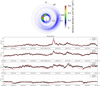 |
Fig. 20 Top: simulation example of the angle-frequency spectrum of wave action at a point in a coastal area, extracted from a two-dimensional geographic model [9]. Such predictions allow calculating the wave statistics for engineering purposes like the design of coastal defense waterworks, e.g. the significant wave height Hm0, the Tm02, the peak period Tp and the mean direction of propagation. Anexample of timeseries of these quantities is displayed on the bottom, for a point located near Brest where buoy data are available for comparison during October 2023; the main peak of Hm0 is the Ciaran storm. |
3.2 Solid mechanics
3.2.1 The containment building of nuclear reactors
The containment building of a reactor building is a prestressed reinforced concrete wall that houses the nuclear facility and must ensure the containment of radioactive substances in the event of an accident. This structure is approximately 50 m high and 40 m in diameter and is characterized by walls that are much thicker than those of a standard building (between 90 cm and 1.20 m). Some of these enclosures are lined on the inside with a metal skin, known as a liner. Regulations require EDF to carry out ten-yearly hydraulic tests (pressurization) to ensure the actual strength of the enclosure.
Given the pressure that the enclosure must be able to withstand in the event of an accident, the level of concrete prestressing is a key factor. However, concrete deforms over time under the effect of various physical phenomena related to water transfer and the current stress state. To monitor the evolution of these deformations over time and during the ten-year tests, the containment structures are equipped with numerous sensors, some embedded in the concrete and others not.
In order to guarantee the enclosure's ability to perform its function for more than 60 years of operation, it is necessary to use numerical simulation to predict the future evolution of these delayed deformations and their impact on the residual compression level of the concrete. This requires modeling that represents the multiple physical phenomena at work, followed by the application of these models in finite element calculations at the scale of the entire structure. Of course, these models are based on a number of parameters that will need to be identified using data assimilation techniques (a task that is all the easier to master as the parameters remain limited in number, the result of a compromise with the fineness of the physical description). All the measurements available on the past behavior of the enclosure are a major asset in this respect. They also make it possible to dispense with a detailed representation of the early years of the concrete (including the construction phase), as knowledge of the initial state of the structure is implicitly obtained during the recalibration phase. We also understand the importance of the wealth of these measurements, which motivate research dedicated to the implementation and use of new types of sensors (optical fibers, in particular). The relevance of this approach has been demonstrated on the VERCORS model that EDF built in 2014-2015. This is a 1/3 scale model of an enclosure, which allows accelerated aging to be observed by a factor of 9, meaning that it is now “older” than any of the enclosures in operation in France.
In addition to aging calculations, EDF also performs damage calculations to more accurately assess the condition of the structure in the event of an accident. This not only results in a rise in pressure but also a sudden increase in temperature in the reactor building, of around 100 degrees. The latter can cause partial cracking of the wall due to thermal deformation. The aim is to predict the thickness of compressed concrete through the wall throughout the pressure and temperature history characteristic of an accident. These finite element calculations, also on the scale of the entire structure, are based on state-of-the-art robust damage models and a representation of the possible plasticization of the reinforcing steel and liner, if applicable.
Finally, for levels equipped with a liner, a final type of simulation can be performed to ensure that the liner itself does not tear in an accident situation. These simulations are based on the previously calculated concrete deformation levels and focus on the liner panels using structural zoom techniques, taking into account in particular the liner anchoring devices in the concrete and the contact between the liner and the concrete. The nonlinearities selected for steel—plasticity and large deformations—then make it possible to evaluate the behavior of the liner, particularly in the vicinity of a possible initial manufacturing defect.
3.2.2 The nuclear reactor vessel
The reactor vessel, together with the reactor building containment, is considered to be the irreplaceable component of a nuclear power plant. Under pressure (155 bar) and at high temperatures (above 300 °C), it contains the fuel assemblies and all the core control mechanisms (the vessel internals, which are replaceable).
The reactor vessel is a large component (3 to almost 5 m in diameter depending on its generation) with a thick wall (200 to 250 mm) made of low-alloy ferritic steel, coated on the inside. Due to the presence of the core, it suffers radiation damage which hardens the material and shifts the brittle-ductile transition of ferritic steel to higher temperatures: the absence of any risk of brittle fracture must therefore be explicitly demonstrated.
This demonstration, scrutinized by the safety authority, is an ongoing task, as it must be updated every 10 years to take into account functional or regulatory changes, as well as the aging of materials. It is a multidisciplinary exercise that combines:
Non-destructive testing (the inner wall of the core cladding is 100% inspected to detect the presence of possible defects);
Neutronics defining the neutron flux received by the vessel (the driver of material degradation);
The study of irradiated material to characterize its behavior and the degradation of its resistance to cracking (or fracture toughness);
Thermohydraulics, which defines the possible transients imposed on the vessel (given its thickness, cold shock situations in the inner wall induced by a safety injection are the most severe loading situations for the vessel);
Structural mechanics, translating thermohydraulic stress into thermomechanical stress.
Mechanical analysis is therefore an essential part of justifying the integrity of the vessel through fracture mechanics (material toughness), fluid mechanics, and solid and structural mechanics. However, given the criticality of the component, this analysis, which must be deterministic, involves significant margins at all levels, whether in terms of material toughness, the definition of thermohydraulic loading, or thermomechanical analysis. In the context of extending the operating life beyond 60 years, these margins may prove prohibitive, hence the R&D work motivated by a better understanding of how the component works and increased modeling capabilities. This is the case, for example, with thermohydraulic transients, which we are seeking to define in a more realistic way (and therefore less severe for the structure), and with failure criteria, which we are seeking to make more physical (and therefore closer to reality). This type of methodological development is obviously discussed with the Regulator and is subject to validation and robustness demonstrations before being included in the justification assessments.
3.2.3 Nuclear reactor fuel assemblies
The various phases of the fuel assembly lifecycle (manufacturing, transport, handling, operation), including those postulated as part of the safety approach (earthquake, loss-of-coolant accident), are analyzed to demonstrate the mechanical integrity of the structure and its components. These analyses also have a performance aspect, in that they aim to ensure that design changes introduced to optimize heat exchange with the coolant (such as intermediate mixture grids), as well as management changes intended to increase the profitability of the units (e.g., extended cycles for the 900 MWe stage), are not likely to adversely affect the mechanical strength of the assemblies.
Leaving aside the effects of irradiation and the primary environment on material performance, the main challenge in analyzing the structural behavior of fuel assemblies lies in the large number of contacts involved, at different and interconnected scales. The contact between the pellets and the rod cladding is a major factor in the local distribution of stresses, which must be taken into account when verifying the mechanical integrity of the first containment barrier; but it also contributes to the damping of the structure and, as a result, to the overall vibration response of the bundle as well as that of the individual rods [10]. The friction between the cladding and the support elements in the grids (around 10,000 contact points per assembly) controls the mechanical hysteresis of the assembly subjected to lateral bending or axial compression stresses. In the reactor core, the clearances between neighboring assemblies and with the partitioning are a major source of nonlinearities due to their number (several thousand) and their small amplitude (on the order of one to two millimeters), particularly in the case of external dynamic stresses such as earthquakes or Loss of Coolant Accidents, which in some extreme cases can cause small-amplitude plastic deformations of the grids. Advances in modeling (see Fig. 21) and the development of new testing methods [12] now make it possible to explicitly describe these nonlinearities, some of which previously had to be addressed using simplifying assumptions that could lead to excessive conservatism in design methods. Since explicit modeling of all these contact nonlinearities at the scale of a complete core is still beyond the capabilities of commercially available computers, a graduated approach can be implemented by combining detailed models representing a portion of an assembly with simplified models whose parameters are adjusted based on the former [13].
The other major contributor to the mechanical response of fuel assemblies in operation is the surrounding coolant. It can act as a driver of mechanical deformation, as in the case of turbulence-induced vibrations or assembly buckling, or intervene as a simple “corrective” term, through inertial effects or induced dissipation, in the case of accident scenarios for which an external dynamic excitation source is postulated. The industrialization of CFD calculation codes has been accompanied by the development of coupling methods that allow the interaction between the fluid and the structure to be modeled explicitly. Here again, several modeling scales can be combined. The explicit representation of turbulent structures (including in unsteady conditions, using methods such as Large Eddy Simulation) is generally limited to small-scale domains, such as the immediate vicinity of the jets at the outlet of the lower core plate, and to specific applications, such as the analysis of the individual vibrational response of fuel rods, for which the feedback effect of the structure on the fluid is most often neglected [14]. These “explicit” models can nevertheless be used to calibrate simplified models based on equivalent pressure drops, which are better suited for integration into core-scale calculation codes to simulate the coupling between the lateral bending of assemblies and transverse redistribution flows (see Fig. 22).
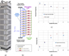 |
Fig. 21 Fuel assembly (a) Nonlinear assembly model (b), natural frequency (c), and structural damping (d) [11]. |
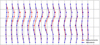 |
Fig. 22 Simulation of assembly arches – comparison between on-site measurements and coupled fluid-structure calculation results [15]. |
3.2.4 Nuclear reactor piping
The various circuits and piping lines in nuclear reactors constitute an extremely complex set of welded piping components, supports, penetrations, etc., of different sizes and diameters. All elements containing primary coolant, like the reactor vessel, form part of the second containment barrier for fission products and are therefore subject to detailed monitoring.
The possible stress modes for such systems are also varied and complex: pressure, of course, but also earthquakes, differential expansion and thermal stratification, mixing/vortex zones between hot and cold fluids, thermal shocks, residual stresses, etc. can all place stress on the piping. In the vast majority of cases, as these modes of stress are difficult to observe or quantify, modeling is used extensively to define the resulting stresses on the piping components (Fig. 23). This is the case at the design stage, and it is also the case for the analysis of operating experience feedback.
 |
Fig. 23 Stress Corrosion Cracking in PWR auxiliary lines: diagram of the R&D strategy in the field of mechanics. |
3.2.5 Dams
EDF operates and maintains a fleet of hydroelectric facilities in France with an average age of around 80 years, the vast majority of which were built between the late 1940s and the mid-1980s. The challenges involved in justifying the mechanical integrity of dams mainly focus on (i) predicting their long-term behavior and (ii) justifying the safety of the facility in relation to flooding and other external stresses (earthquakes, wind, rockfalls, etc.), in order to support the regulatory risk analyses of hazard studies.
Each dam is unique in terms of its dimensions, the materials used in its construction, the construction methods employed, and its geological environment. Numerical modeling is used to determine the mechanical condition of the structure in its environment, taking into account the aging mechanisms of the materials, the historical behavior of the structure, and thermal, hydraulic, and mechanical loads. The mechanical study of dams also draws on monitoring data (displacements, water pressures) recorded since the structure was filled with water, and on laboratory and in-situ tests to determine the behavior of the materials used in its construction.
For concrete dams, behavior models are developed and implemented to take into account: (i) areas with high localized non-linearities known in advance (e.g., interfaces between the dam and the rock, pad joints) and (ii) loss of concrete stiffness due to damage, mainly in the case of structures with swelling pathologies. The same models are also used to justify potential reinforcement solutions.
In addition to very good international feedback on earthquake resistance, where necessary, the demonstration of the structures' seismic performance is based on the implementation of numerical models integrating: (i) modeling of the seismic wave, its radiation and attenuation around the structure, (ii) the dynamic behavior of the structure and its interaction with the foundation and the dam, incorporating the specific characteristics of the cyclic behavior of the materials of which it is composed. For concrete arch dams, fluid-structure interaction with the reservoir is a key aspect of their dynamic behavior and seismic response; specific developments have been implemented in Code_Aster to increase its numerical efficiency. An embankment dam, on the other hand, may be sensitive to the gradual increase in water pressure within it during the cycles imposed by seismic loading; it is therefore necessary to take this into account through hydro-mechanical modeling and behavior models adapted to this phenomenology of liquefaction of the dam and/or its foundation.
4 Ongoing scientific challenges
Even though the field of electricity generation benefits from continuous advances in research in various mechanical engineering disciplines, the requirements of industrial integration impose specific constraints on these disciplines, which translate into challenges that must be overcome. Some examples are given below.
4.1 Fluid mechanics
4.1.1 Experimental field
Experimental fluid mechanics is an incredibly vast field, encompassing everything from turbulent velocity measurements using Time-Resolved Particle Image Velocimetry (TR-PIV), to temperature sensing in cryogenic environments with compensated micrometric thermocouples, and two-phase flow analysis with high-speed cameras—and much more. Often, the first and most powerful tool of the experimentalist is simply the naked eye—used to observe, interpret, and choose the most appropriate measurement technique for the flow studied. Note that experiments in cryogenic environments, although expensive, are a serious candidate to perform experiments close to the real conditions in terms of non-dimensional numbers such as the Reynolds or the Grashof numbers.
Once a technique is selected and properly calibrated, it can reveal new insights into the behavior of the fluid. Today, artificial intelligence is pushing the boundaries of data analysis, opening new possibilities for interpreting complex flow phenomena.
Let’s consider two-phase flow measurements with high-speed camera in Figure 24a. The camera captured a thousand bubbles with varying shapes and volume. Traditional tracking algorithms can, usually, track a bubble until it collides with or is obscured by another, often losing track for several frames. Reconnecting trajectories becomes a major challenge. With AI-enhanced segmentation tools like SAM2 (Segment Anything Model 2, [6]), we can now track individual bubbles continuously, even through complex interaction (see Fig. 24b).
However, while segmentation and tracking have improved, current tools still struggle with physical constraints like conservation of volume. This can lead to abrupt changes in estimated surface area and center of gravity over time, introducing uncertainty.
AI in general could be seen as the next revolution in research and especially in experimental fluid mechanics in its capabilities to uncover patterns in massive datasets. However, a key challenge remains interpreting AI-generated results with scientific rigor, understanding their relevance, and quantifying their uncertainty, all while considering the environmental cost of these powerful computational resources.
 |
Fig. 24 Two phase flow captured with high-speed camera (a) and bubble segmentation with AI-improved tool -SAM2 (Segment Anything Model 2) (b). |
4.1.2 Turbulence and heat transfer modeling
On area where progress is needed is that of the modeling of the Reynold stresses. Second order moment closures have been derived but the corresponding “Reynolds stress models” are not as robust as the more standard eddy viscosity models, their numerical implementation is less easy and there are questions about solution realizability. An increase in maturity is needed if one wishes to use such models in place of the common eddy viscosity models.
One topic that is less well covered is that of the modeling of turbulent heat-fluxes which are quite important in heat transfer applications. This is so for several reasons, one of them being a lack of experimental or numerical data (originating from Direct Numerical Simulation or from fine Large Eddy Simulation) compared to the much larger databases available for momentum tranfer in constant temperature flows. The lack of experimental data is probably to the more difficult and more costly experimentation required. More developments are needed to improve turbulent heat fluxes modeling in mixed and natural convection regimes [16].
Finally, the widely used “standard” wall functions that are used at the boundaries also constitute a weak point in the modeling and deserve further attention and might perhaps be improved by making use of AI machine learning methodologies.
4.1.3 Friction modeling
Contrary to popular belief, the Navier–Stokes equations (for 3D models) are imperfect. This is mainly because they represent shear stresses using an elliptical model (the viscous model), thereby transmitting these stresses instantaneously, contrary to the physical principles of propagation and causality. Establishing a system of hyperbolic (i.e., propagative) equations for shear flows is a still underestimated need and a major scientific challenge. This is particularly important for transient flows, such as the dynamics of fast surface waves (dam breaches, waves, intumescent waves). More generally, the usual formulas for wall friction in analytical and numerical models fail in transient regimes, regardless of the spatial dimension of the work. This results in poor estimates of head loss calculations in transient regimes.
4.1.4 Free surface hydraulics
Because it is the mobile location of a boundary condition, a free surface is coupled non-linearly to the mass of water it contains. For 3D models, the difficulty lies in accurately capturing its position. For 1D and 2D models, where water height is an explicit variable, the problem is to correctly represent the distribution of the variables of interest in the water column (2D models) or in the channel or river section (1D models). The Saint-Venant equations, for example, which are available in 1D and 2D versions, are based on the assumption of hydrostatic pressure, which limits them to represent very long waves (typically more than 25 times the depth). One of the main questions still open is how to improve this type of model by using more realistic assumptions without ending up with overly complex equations (Serre–Green–Naghdi equations, for example). For modeling, the mathematical and numerical treatment of these families of equations is also a challenge.
Beyond sedimentology, other types of “inclusions” in natural fluids are of interest for the management of power generation facilities, such as frazil ice (risk of ice formation in the water intake channels of nuclear power plants, for example) and air bubbles (modeling of white water downstream of large dam spillways). 1D, 2D, or 3D models can be used depending on the conditions. This is the most complex physics that hydraulic engineers have to deal with, apart from turbulence and interactions with living organisms, which are discussed below.
4.1.5 Interactions with living organisms
The phenomena mentioned above often interact with vegetation and wildlife: clogging of filtration screens at nuclear power plant water intakes due to the massive influx of floating vegetation, modeling of water friction on a floodplain with complex and flexible vegetation, taking into account the presence of microorganisms in the aquatic environment near nuclear power plants (amoeba, Legionella), modeling the hydro-ecological status of lakes and reservoirs (the case of the Etang de Berre is emblematic), etc. In particular, understanding microbial populations and representing aquatic photosynthesis are increasingly being coupled with the study of water quality.
4.1.6 Two-phase fluid mechanics
Water/steam flows are particularly important in the nuclear industry. They occur in many situations during normal operation (pressurizers, steam generator, etc.), incidents (in primary pumps), and accidents (depressurization of the primary circuit).
Understanding two-phase water/steam flows is therefore a major challenge. This challenge has led to the creation of dedicated system codes during reactor design. These codes provide valuable insights into the overall behavior of reactors, enabling their safety to be demonstrated.
Today, it is becoming increasingly important to go beyond this “large-scale” description of two-phase flows in order to represent the details of the flows. Indeed, on a local scale, two-phase flows have a significant impact on:
The intensity of heat transfer and therefore the power that can be removed from the core or the cooling power that can be removed from a given piece of equipment.
Pressure drops.
Pressures in enclosures where steam may be present (including the reactor pressurizer).
Two-phase flows are characterized by the presence of a liquid/vapor interface, the shape of which can be extremely complex. Precise knowledge of this interface is important because it governs heat and mass transfer in the flow. However, its shape varies greatly depending on the relative quantities of liquid and gas, temperatures, geometries, etc.
Current research in fluid mechanics aims to provide solutions for studying these flows in all their complexity within a reasonable time frame in order to:
Correctly evaluate the performance of equipment involving two-phase flows by limiting the number of costly tests required for their design
Correctly evaluate the thermal loads on equipment in these situations
Enable fine design optimizations
These code developments, such as Neptune_cfd, require dedicated experimental data.
4.1.7 Multiphysics and multiscale challenges
The French nuclear industry is committed to the continued development and improvement of thermohydraulic tools used for the design and safety demonstration of power plants. One example is the CATHARE and Neptune_cfd codes developed jointly by EDF, CEA, Framatome and ASNR. The CATHARE code [17] is the French benchmark for safety analyses of pressurised water reactors. Complementing this system approach, the Neptune_cfd multiphase CFD code [18] can simulate flows on a local 3D scale, thereby enhancing understanding of the physical phenomena involved in more complex flows.
These tools will ultimately contribute to the implementation of digital twins, enabling multiphysics and multiscale simulation of industrial systems; they will be gradually introduced during the commissioning and operation phases of future power plants. These advances in numerical tools are closely linked with the implementation of new calibrated experimental bench for validating physical models. Current efforts on scaling methods aim to maximise the representativeness of these facilities with regard to key thermohydraulic phenomena and to quantify distortions, where applicable.
Passive systems involve physical behaviors that require further expertise and analysis: natural circulation driven by generally weak and time-variable forces, heat transfer in large volumes, boiling and condensation mechanisms, potential dynamic and oscillatory instabilities, etc. Moreover, questions remain about the actual energy extraction performance of passive systems due to strong couplings between complex physical phenomena and a lack of experimental references to validate initial estimates.
Fire is one of the most important risks at nuclear power plants, as highlighted by safety assessments across many plants [19]. Traditionally, fire safety in nuclear power plants relied on a prescriptive approach, following strict, pre-defined rules and regulations. However, the need for a more flexible approach during modifications and innovative nuclear plant argues for a shift toward a more effective risk-informed and performance-based (RIPB) approach because a blend of theoretical, computational and experimental methods address tomorrow's risk challenges. A fire scenario is a specific chain of events that starts with the ignition of a fire and ends either with plant shutdown or core damage. Consequently, it's difficult to predict how a fire will spread and what its severity will be within the complex environment of a nuclear power plant. This includes understanding the inherent complexity of the phenomenological behaviour of fire in confined spaces and the impact on a wide variety of materials and components. This is quite challenging as a fire is a complex multi-physics and multi-scale problem involving buoyancy-controlled flows, buoyancy-induced turbulence, turbulent combustion, thermal radiation, soot production, burning rate, and heat feedback.
Last but not least, coupling the neutronics with the thermohydraulics is essential in the future. Fission probabilities, known as fission cross-sections, are highly dependent on thermohydraulics. Neutronic calculation is a system made up of neutronic, thermal-hydraulic and thermal solvers, which are interdependent at each step. A neutronic calculation requires solving multiple physics which needs strong coupling (Fig. 25).
 |
Fig. 25 Diffusion equations and calculation scheme for neutronics computations. |
4.1.8 Computational resources
This document presents numerous examples of the usefulness of fluid mechanics calculations.
However, in order to benefit from these advantages, it is necessary to use validated methods and appropriate models. These methods and models in turn require modeling and, in particular, time and space discretization that is fine enough to represent the phenomena in all their complexity.
These fine discretizations require significant computing resources. Hundreds of millions of hours of computing time are consumed annually on dedicated clusters to process these phenomena.
Three factors exacerbate this situation:
The search for robustness in demonstrations. This robustness is achieved at the cost of simulating multiple variants of the problem in order to quantify its potential variability and demonstrate the stability of the solution (absence of a “cliff” effect capable of radically changing the conclusions of a study if the assumptions change in a limited way).
The extension of calculation domains. One of the frequent causes of representativeness flaws in numerical analyses is the presence of (imperfect) boundary conditions too close to the areas of interest. Increases in available computing power make it possible to represent larger domains and to avoid boundary conditions that are too close or destructive margin decouplings.
Finally, the representation of more complex phenomena can drastically change the scale of available computing power. For example, subjects such as two-phase or unsteady fluid mechanics require computing power two orders of magnitude greater than that of “standard” single-phase analyses.
Faced with the challenge posed by the available computing power, several solutions are being explored:
Improvement of algorithms: However, these are already highly optimized.
Improvement of models: In recent years, the scientific community has worked extensively on new-generation turbulence models that can produce high-quality results more quickly.
Solving different physical equations to represent phenomena (“Lattice Boltzman Methods” analyses that statistically describe particle collisions or “Smoothed Particles Hydrodynamics” that represent fluid as a set of “fluid particles” governed by interactions). While these approaches yield real gains in some cases, they are still limited in many “classical” applications.
Hardware improvements: many software publishers are porting CFD codes to GPGPU, with substantial performance gains (a factor of more than 10). However, the price of hardware still limits the scope of these solutions for economic reasons.
Artificial intelligence, with its advanced interpolation capabilities, is also being studied both to interpolate result databases (a posteriori approach) and to aid code convergence (a “hybrid” approach).
Depending on the numerical scheme’s stability constraints, time steps are limited, requiring many such steps in a simulation. Also, many models used in CFD do not fit on a single computational node, so all relevant codes distribute their computation on multiple nodes of a cluster with a high-speed network, usually through the Message Passing Interface (MPI) approach.
Running large models in practice greatly benefits from “in situ” and parallel pre and post processing, as simulations can produce much more raw data than can physically be moved. HPC involves a whole tool chain, not just computation.
Numerical methods with explicit time stepping are easier to parallelize but often require many very small-time steps. Implicit or semi-implicit methods can enable larger time steps but are more dependent on linear algebra solvers. Higher order methods such as spectral elements, Discontinuous Galerkin (DG), or Hybrid High-Order (HHO) can also put a lot of strain on linear algebra solvers. Methods such as LBM can make very good use of current computing resources for some flow types but have limited accuracy (and thus relevance) for many others.
As hardware trends are driven by a combination of market demand and attainable “operations per Watt”, there is a strong trend towards use of general-purpose GPU, whose development today is driven mainly by AI requirements. To exploit the higher throughput of those architectures, CFD codes must adapt to a lower level of support for cross-vendor standards and languages and exploit a finer degree of parallelism. As moving data requires more energy than computation, schemes with a high computational intensity (such as using dense matrix-matrix multiplications) can make better use of current and future hardware. Making good use of the available low-precision arithmetic units is also a challenge.
Significant progress has been made recently updating major codes to these architectures, and development in a heterogeneous hardware landscape needs to be made sustainable through improved programming techniques. This also involves training both new and current developers in some HPC fundamentals. Continued academic research in numerical methods and linear algebra is also needed.
4.1.9 Mesh generation
Mesh generation is the first step to carry out a computation. While finite volume techniques are commonly used in CFD, the superiority of hexahedra compared to other kinds of elements is undoubtedly. However, the domains are more and more complex (the vanes, dimples and springs of a mixing grid of a fuel assembly is a perfect example of complexity) and the use of polyhedral or tetrahedral elements becomes mandatory as producing fully hexahedral meshes for very complex geometries is time consuming if not impossible. The commercial mesh generators such as the ones available in StarCCM+ or Ansys platform have made a lot of progress for these two kinds of elements, but more research should be performed to create quasi-hexa meshes to decrease the errors due to cell volumes jumps or non-orthogonalities at the face separating two elements.
Note that the evolution of code capabilities seems to be faster than those of the mesh generator. Today, tens of billions of computational cells can be used with supercomputers and a “reasonable” number of cores (few thousands) but the meshes are usually generated for simple geometries having patterns such as tube bundles.
Finally, the use of refinements in the real configurations comparable to those of the validation usually at a lower scale is still marginal as the mesh would require much more computational cells. The use of wall-resolved turbulence models in the near-wall region is also limited, even in experimental configurations, because of the required refinements.
Adaptive mesh refinement (AMR) is a solution to optimize the computational mesh, and a lot of work is ongoing today to refine the solutions where the velocity or the temperature gradients are important. Immersed boundary method (IBM) is also a solution in which a computational cell is “simply” cut by the wall surface. This solution is straightforward with a finite volume solver which deals with cells of any shape. However, the low discretization order utilized in widely used commercial or open-source CFD tools might be a limitation for this approach and more investigation and research is needed.
4.1.10 Uncertainties
The use of 3D fluid mechanics codes to support safety analyses requires:
The validation of a calculation code as described in Section 2.1.3. This operation essentially consists of demonstrating that, if the boundary conditions (operating conditions, geometry, etc.) of a problem are well known, the code is capable of predictively providing the evolution of the quantities of interest.
The validation of a calculation method. The objective is to demonstrate that the uncertain or poorly known parameters of the problem are treated in such a way as to guarantee that the result provided by the code is penalizing with respect to the safety issue under study. In the real world, the parameters of the problems studied are rarely known perfectly, so the problem must be handled in such a way as to ensure that the demonstration covers all possible situations.
This demonstration can be carried out by identifying a so-called “bounding” set of parameters, which penalize the result with respect to the safety objective (maximum temperature, maximum pressure, maximum loading, etc.). However, there are situations in which several physical phenomena compete with one another, making it difficult—if not impossible—to define a priori a bounding set of parameters.
When this occurs, an analysis is performed by adopting penalizing assumptions for the parameters for which this is possible, and by conducting an uncertainty analysis around a reference solution in order to demonstrate that the probability of exceeding a given criterion remains low and controlled, or preferably null.
In the case of three-dimensional Computational Fluid Dynamics (3D CFD) analyses, this uncertainty analysis is particularly challenging. Indeed, estimating the uncertainty of the solution requires performing numerous variations of the analysis by modifying uncertain parameters, and each computation may be very costly (see the section on “computational time”).
For this reason, the nuclear industry has invested in uncertainty quantification methods. These methods consist in carefully selecting sensitivity calculations so as to ensure, with a high level of confidence, that an accurate representation of the probability distribution of the output quantity has been obtained, thereby enabling probabilistic reasoning. This informed sampling approach is the subject of a dedicated OECD position paper [20].
4.2 Solid mechanics
4.2.1 Methodology and cross-cutting issues
The challenges can be summarized in three key areas: robustness, performance, and reliability. All relevant studies aim to facilitate informed decision-making, and scientific obstacles and challenges are therefore addressed using this approach, based on these three criteria.
Firstly, the reliability of numerical models depends on taking into account the close link between physical phenomenology, the underlying mathematical model, and its transformation into problems that can be solved by computer. The first challenge concerns the consideration of phenomena with discontinuities, i.e., the modeling of damage, fracture mechanics (incorporating local (visco)plasticity phenomena), the modeling of contact and friction, and calculations in non-regular dynamics (shocks, impacts). The scientific obstacles relate as much to the consideration of physical phenomena: specific constitutive equations in fracture and damage mechanics, restitution of the complexity of contact/friction interaction on interfaces (digital tribology, wear), or conservation of fundamental quantities in physics such as energy in dynamics.
Even for physical models with well-established mathematical formalism (such as Coulomb friction contact), the scientific challenges are linked to fundamental mathematical problems such as proving the existence and uniqueness of solutions, the regularity of solutions, and mathematical properties in general (coercivity, symmetry, etc.). In addition, the transition from the continuous model to the discrete model (the only one accessible to practical numerical resolution) brings numerical specificities such as the consistency and stability of solutions.
Problems of non-regular dynamics and Coulomb friction, for example, present open questions from a mathematical point of view, and their translation into discrete problems can also present specific numerical pathologies (parasitic oscillations, dependencies on parameters such as meshing, difficulty in establishing conservation laws). Methods for discretizing partial differential equations or ordinary differential equations (finite difference, finite element, or finite volume methods) are well established and widely used in industrial practice. However, they have intrinsic limitations such as the limited choice of geometric supports (meshing), the choice of low-order polynomial functions, the continuity requirements of certain quantities, the approximation methods of weak formulations (numerical quadrature), and the stability problems associated with mixed approaches (known as the inf-sup condition).
It is becoming increasingly apparent that, even for problems that are well solved by these classical discretization methods and well developed industrially, the limitations they entail require the development of new approaches based on overcoming the underlying assumptions, such as not limiting oneself to a conforming and regular mesh or low order of convergence.
Discretization methods have therefore been developed to overcome these assumptions, almost all of which are based on approaches from the Discontinuous Galerkine family, for which the best one must be chosen, taking into account the problems and limitations of conventional software architecture (so-called “legacy” calculation codes) in order not to lose the benefit of decades of development of these solutions and the heritage associated with the concrete resolution of industrial problems.
This last point gives us access to the first aspect of ensuring the credibility of the solutions provided by numerical approaches and their robustness in a real industrial context. From a scientific point of view, this involves developing methods that take into account the variability of input data, which stems either from imperfect knowledge of the data (calculation of uncertainty propagation) or from the need to ensure reliable limits for the results obtained, in order, for example, to limit “cliff” effects.
Massive parametric calculation is, in general, a challenge for the future when it has to solve large-scale problems (in space and/or time) for parameters that are often difficult to identify or even take into account. Dimensional reduction techniques need to be developed, always with a view to avoiding the curse of dimensionality and dealing with difficult, highly non-linear problems.
In the latter case, we can cite ill-posed problems (multiple solutions, for example) resulting from the loss of ellipticity of equations and using variational inequalities such as contact/friction or damage modeling, or hyperbolic propagation problems. The other difficulty concerns problems that are not naturally parametric, such as those with geometric variability and those with parameters that are not identified a priori and/or are too numerous.
In general, fundamental mathematical work is still underway to develop reduction techniques for nonlinear problems. In this category of problems, we also consider the modeling of slender structures classically used in structural mechanics (beams, plates, shells) and their extension to nonlinear problems (large deformations, structural instabilities, nonlinear behavior laws).
Finally, from an industrial perspective, there are two key themes: the interaction between measured data and simulated data (data assimilation and recalibration methods) in the context of “digital twin” and hybrid approaches, which are necessary for the operation of very long-life structures such as those found in the energy production domain, but also the quality of the solutions obtained from an engineering point of view, i.e., methods for error estimation and results certification, which are closely intertwined with industrial practices, the deployment of strategies developed by methods departments, and the training of design engineers in the broadest sense. Finally, the reliability and robustness of solutions obtained using software tools cannot be achieved without developing techniques to ensure the quality of V&V (verification and validation) files. These techniques are both deeply digital in nature (propagation of rounding errors, reliability of parallel computer architectures) and methodological in nature (intertwining of measured data and large-scale experimental campaigns).
The question of using artificial intelligence methods remains to be addressed in a field (digital modeling) whose reliability and results are well established from a formal standpoint and regarding industrial practice. The successful hybridization of the best of these two worlds remains to be built.
The other side of solving discrete problems concerns the issue of their compatibility with new computer architectures, both in terms of the nature of the computing units (CPU, GPU) and the limitations associated with memory and massive parallelism. We are talking here, for example, about high-performance computing (HPC) on thousands of parallel cores, which require approaches that are radically different from conventional ones, not to mention the need for an efficient (and energy-efficient) approach. Among the obstacles identified from this point of view is the lack of solutions in terms of linear algebra on these architectures for “saddle point” problems, which are widely used to overcome numerical locking problems and the extension of methods to new discretization techniques producing discrete systems of a different nature (matrix filling, loss of symmetry, the need for higher precision, or the consideration of complex algebra).
Finally, still from the perspective of solving large-scale industrial problems, the issue of storage, the durability of the data produced, and its efficient processing remains a challenge.
4.2.2 Flow induced vibration in nuclear power plants
Experience has shown that scale testing, when effectively coupled with simulation, offers the most reliable design strategy in vibration-sensitive systems. This hybrid approach enables engineers to validate numerical models against observed physical behavior, mitigate uncertainties linked to boundary conditions, and gain deeper insight into the phenomena occurring at the scale of actual facilities. By combining the strengths of both methods, this mixed methodology enhances confidence in design decisions and significantly reduces the risk of unwanted resonances and instabilities. The remaining challenge lies in extending traditional component-level tests to include their operational surroundings, in order to better predict real-site behavior and interactions.
Another challenge consists in properly describing flow-induced wear in flexible structures with gap supports. Configurations where fretting wear significantly alters the structure are particularly sensitive to localized flow effects and contact dynamics. A key long-term concern is whether this wear accelerates spontaneously. In certain cases, minor initial damage can modify the local geometry or stiffness, amplifying flow-induced forces and triggering a self-reinforcing degradation process. Capturing this evolution requires advanced modeling approaches that integrate fluid dynamics, contact mechanics, and material response, supported by targeted experiments to validate wear progression under representative operating conditions.
A final challenge consists in defining vibrational acceptance criteria for valves and rotating machinery. These components often operate under complex flow conditions and may generate significant pressure fluctuations and transient loads, potentially exposing parts of the facility to fatigue failure. The difficulty lies in establishing criteria that are both conservative enough to prevent damage and practical enough to guide design and diagnostics. Moreover, these criteria must remain effective when transposed from controlled test rigs to real operating environments, where installation conditions and flow regimes can vary significantly. Achieving this requires a robust framework that combines experimental data, simulation insights, and field experience.
4.2.3 Welding and residual stresses
The industrialization of digital simulation tools for welding and related processes (finishing, post-welding heat treatment, mitigation, etc.) continues, building on the progress made in this field during the SCC issue that has affected the main primary system auxiliary piping made of austenitic stainless steel since the end of 2021, as well as on solid knowledge bases and validated modeling principles that have been the subject of research since the mid-1980s.
The main principles of Computational Welding Mechanics (CWM) consist of managing the input of material and heat while respecting the real time of welding as closely as possible (thermal aspect - knowledge of the process) and describing the non-linear behavior of the materials in the assembly over a wide temperature range up to the solidus temperature (mechanical aspect - materials) in a transient resolution process that integrates the local effects of material history and structural effects. These models are based on the use of thermomechanical calculation codes such as Code-Aster, some of whose features are specific to high-temperature processes, such as the application of equivalent heat sources and the use of nonlinear constitutive equations that take microstructural effects into account. With the aim of predicting residual welding stresses, a PIRT-type analysis confirms that modeling the distribution of heat source power per unit volume has a significant impact on the level of residual stresses (thermal aspect – knowledge of the process). This analysis also shows that an adequate level of knowledge of the mechanical behavior of the material as a function of temperature is necessary to obtain the best estimates of stresses through numerical simulation of welding.
To illustrate the nature of the CWM problem on the material aspect with a view to predicting residual stresses, a blocked dilatometry test can be performed numerically to represent the fact that, during welding, the area close to the weld bead is said to be self-clamped. This term refers to the blocking effect exerted by the colder parts of the workpiece around the hot zone of the weld being made. To explain the mechanisms that lead to the appearance of residual stresses in this region, the blocked dilatometry test consists of heating and then cooling the useful area of a cylindrical test piece whose axial movements are blocked in a uniform manner. This test, now used to understand the appearance of residual stresses and quantify the weight of the various phenomena observed during a welding operation, was first implemented by K. Satoh [21], hence the common name for this family of tests, “Satoh tests” (Fig. 26). For this last test, in the absence of metallurgical transformation and in the case of elastoplasticity, the material which is initially free of any stress, is first subjected to compression because thermal expansion is prevented by clamping. This compressive stress increases until it reaches the yield stress and then decreases with temperature in conjunction with the yield stress of the material. The level of axial stress, also limited by the yield stress of the material, whose evolution with temperature is shown in dotted lines, follows the evolution of the latter, except for work hardening, to reach an extremely low level at very high temperatures. Upon cooling, thermal shrinkage is prevented and this time causes the representative elementary volume of the test piece to be placed under tension. After returning to room temperature, the level of residual tensile stress depends on the expansion of the elastic range at high temperatures and the thermal path traveled.
EDF's interest in maintaining and developing experimental and numerical expertise in the sub-field of welding, which belongs to the broader field of mechanics for Nuclear Pressure Equipment, is crucial in manufacturing and operation in order to understand the issues that can affect welded assemblies, while proposing ways to remedy them through mechanical justifications for continued service, desensitization to certain failure modes through mitigation, repairs using optimized processes, or partial replacement of equipment. In this regard, we can mention the activities of the European NeT network [22] (Fig. 27), which aim to industrialize, through benchmarking campaigns targeting representative models of material/process combinations in the nuclear industry, experimental and numerical methods for estimating the material behavior of welded assemblies and residual stresses. We can also mention the work [23] on estimating residual stresses on real components (ESPN tube-elbow assemblies) in support of the SCC issue (Fig. 28).
Addressing issues related to the mechanics of welded assemblies requires broadening and deepening our understanding of the physical mechanisms generated by welding and, at the same time, ensuring the ability to reproduce this physics through modeling and simulation in order to predict the mechanical consequences of welding depending on the type of process, operating conditions, materials, and configuration. These scientific and technical objectives present challenges to be overcome and obstacles to be removed.
The mechanical properties of welded assemblies can play an important role in the degradation mechanisms that impact operating facilities. Experimental and numerical approaches deployed on instrumented physical models provide insights into the role of welding in sensitizing assemblies to phenomena such as stress corrosion cracking. Deepening our knowledge and thus better protecting ourselves from degradation mechanisms is an important objective that will require overcoming several obstacles to be achieved:
Enriching numerical models by taking the physics of welding into account in a more realistic way. Certain modeling assumptions used in standard simulation methods must be removed and replaced with modeling ingredients that better represent physical phenomena. This includes, in particular, multi-scale approaches that make it possible to transcribe phenomena operating at the microstructure scale to the structure scale. Approaches exist in the literature but implementing them in industrial welding applications and providing validation elements is a challenge.
Develop and deploy measurement techniques to (1) feed models with more realistic data in order to characterize welding operating conditions and various in-service stresses, and (2) evaluate quantities of interest such as residual stresses, which to date can only be measured using destructive methods.
Develop innovative measurement methods, in particular for in-situ observation of the mechanisms at work during welding at the microstructure level (hot cracking).
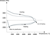 |
Fig. 26 Principle of a blocked dilatometry test, Satoh test, which reports on the behavior of the material and provides insight into the processes involved in the generation of residual welding stresses. |
 |
Fig. 27 NeT Network Task Group TG4: Results of benchmarking on the estimation of residual stresses (CWM and neutron diffraction) on models that can be transposed to actual components. |
 |
Fig. 28 Stress corrosion cracking of PWR auxiliary lines: Measurement of residual stresses using the deep hole drilling (DHD) method (left) and comparisons after weld desensitization by mitigating residual stresses using a post-weld mechanical process (compression of the inner half of the assembly demonstrated by CWM and measurements). |
5 Conclusion
The work presented highlights the fundamental contribution of mechanical sciences to the design, understanding, and safety justification of energy-generation systems operating in complex and strongly coupled physical environments. The wide range of phenomena involved—turbulent flows, heat transfer, material ageing, nonlinear structural behavior, fluid–structure interactions, and accident-induced transients—requires an integrated approach combining advanced modelling, multi-scale experimentation, and uncertainty quantification. The parallel development of modern instrumentation, three-dimensional imaging techniques, high-performance computing capabilities, and multiphysics models significantly enhances the predictive accuracy of simulation tools and strengthens their relevance for safety demonstrations.
In a context marked by lifetime extension of existing facilities, rapid expansion of renewable energy systems, and increasing requirements for robustness, numerous scientific challenges remain: refinement of physical models, improved representation of nonlinear transient behaviors, mitigation of scale-model distortions, accurate modelling of fluid–structure coupling and multiphase flows, and rigorous integration of uncertainties. Addressing these challenges requires a tight interplay between academic research, industrial feedback, and methodological innovation.
Thus, mechanics—encompassing fluid mechanics, solid mechanics (including mechanics of materials), structural analysis, and numerical modelling—remains a scientific cornerstone for ensuring the safety, performance, and long-term durability of electricity-generation systems. By strengthening the synergy between experimental and numerical approaches and advancing validated, robust methodologies, the scientific and industrial communities are equipped to support the evolution of the energy mix and meet strategic objectives of sovereignty, efficiency, and resilience.
Funding
This research received no external funding
Conflicts of interest
The authors have nothing to disclose
Data availability statement
This article has no associated data generated and/or analyzed.
Author contribution statement
Writing – Original Draft preparation, S.L., M.A., V.A.F., S.B., S.C., S.H., E.L., S.M.P., P.M., V.R., D.V., V.F., N.G., J.P., N.M., P.M., G.P.
References
- V. Fichet, M. Daoudi, L. Zimmer, Simultaneous control rod 3D displacement and 3D ow measurements via time resolved 3D3C PTV with one camera only, in Proceedings of the 12th International Conference on Flow-Induced Vibration, Saclay (2022) [Google Scholar]
- M. Bruschewski, K. John, C. Wüstenhagen, M. Rehm, H. Hadžić, P. Pohl, S. Grundmann, Commissioning of an MRI test facility for CFD-grade flow experiments in replicas of nuclear fuel assemblies and other reactor components, Nucl. Eng. Des. 375, 111080 (2021) [Google Scholar]
- M. Neumann-Kipping, A. Bieberle, U. Hampel, Investigations on bubbly two-phase flow in a constricted vertical pipe, Int. J. Multiph. Flow 130, 103340 (2020) [Google Scholar]
- S. Benhamadouche, On the use of (U)RANS and LES approaches for turbulent incompressible single phase flows in nuclear engineering applications, Nucl. Eng. Des. 312, 2–11 (2017) [Google Scholar]
- https://reglementation-controle.asnr.fr/reglementation/guides-de-l-asnr/guide-de-l-asn-n-28-qualification-des-outils-de-calcul-scientifique-utilises-dans-la-demonstration-de-surete-nucleaire [Google Scholar]
- N. G.-T.-Y. Ravi, SAM 2: Segment anything in images and videos. From Computer Science - Arxiv: https://arxiv.org/abs/2408.0071 (2024) [Google Scholar]
- S. Benhamadouche, M. Arenas, W.J. Malouf, Wall-resolved Large Eddy Simulation of a flow through a square-edged orifice in a round pipe at Re = 25,000, Nucl. Eng. Des. 312, 128–136 (2017) [Google Scholar]
- E. Catel, E. Lorentz, A. Dahl, J. Besson, A gradient-enhanced GTN model with Lode-dependent nucleation for ductile fracture in ferritic steels: From specimens to structural components, Eng. Fracture Mech. 331, 111703, (2026) [Google Scholar]
- A. Villefer, Étude des processus de submersion de protections côtières par LES vagues pour des états de mer complexes, Mécanique des fluides [physics.class-ph]. École des Ponts ParisTech, Français. ⟨NNT : 2022ENPC0029⟩. ⟨tel-04076455⟩ (2022) [Google Scholar]
- G. Ferrari, P. Balasubramanian, S. Le Guisquet, L. Piccagli, K. Karazis, B. Painter, M. Amabili, Non-linear vibrations of nuclear fuel rods, Nucl. Eng. Des. 338, 269–283 (2018) [Google Scholar]
- J. Pacull, G. Deuilhé, F. Errico, Non-linear modeling of PWR fuel assembly dynamic behavior in earthquake and local, Transactions, SMiRT-26, Berlin/Potsdam, Germany, July 10–15 (2022) [Google Scholar]
- V. Hatman, E. Bourdais, B. Matthews, A. Poulat, J. Pacull, Method Advancements for Fuel Assembly Spacer Grid Dynamic Characterization for Seismic and LOCA Events, TopFuel 2025, Nashville, Tennessee (2025) [Google Scholar]
- B. Leturcq, P. Le Tallec, S. Pascal, O. Fandeur, N. Lamorte, A new reduced order model to represent the creep induced fuel assembly bow in PWR cores, Nucl. Eng. Des. 394 (2022) [Google Scholar]
- D. Tumbajoy-Spinel, J. Pacull, M. Quenehen, H. Hadzic, B. Painter, H. Marr, E. Rigaud, Simulation of nuclear fuel rod vibration and analysis of grid-to-rod wear fretting risk, FIV 2024 proceedings, Iguaçu Falls, Brazil (2024) [Google Scholar]
- N. Lamorte, E. Méry de Montigny, N. Goreaud, B. Chazot, V. Marx, Advanced predictive tool for fuel assembly bow design performance evaluations, TopFuel 2021 Proceedings, Santander, Spain (2021) [Google Scholar]
- F. Dehoux, S. Benhamadouche, R. Manceau, An elliptic blending differential flux model for natural, mixed and forced convection, Int. J. Heat Fluid Flow 63, 190-204 (2017) [Google Scholar]
- R. Préa, P. Fillion, L. Matteo, G. Mauger, A. Mekkas, CATHARE-3 V2.1: The New Industrial Version of the CATHARE Code (2020) [Google Scholar]
- A. Guelfi, D. Bestion, M. Boucker, P. Boudier, P. Fillion, M. Grandotto, J.-M. Hérard, E. Hervieu, P. Péturaud, NEPTUNE: a new software platform for advanced nuclear thermohydraulics, Nucl. Sci. Eng. 156, 281–324 (2007) [CrossRef] [Google Scholar]
- Experience Gained from Fires in Nuclear power Plants, IAEA-TECDOC-1421. IAEA, Vienna, Austria (2024) [Google Scholar]
- P. Ruyer, B. Ioss, J. Baccou, L. Sargentini, A. Ghione, N. Goreaud, E. Fekhari, N. Merigoux, J.-F. Wald, R. Ji, S. Kelm, R. Underhill, C. Viron, J. Roy, Uncertainty quantifications for CFD, a review of issues and proposals, CFD4NRS Proceedings, Mito, Japan, Upcoming OCDE position paper (2025) [Google Scholar]
- K. Satoh, Transient thermal stresses of weld heat-affected zone by both-ends fixed bar analogy and thermal stresses developed in high-strength steels subjected to thermal cycles simulating weld heat-affected zone, Trans. Jpn. Weld. Soc. 3, 125–142 (1972) [Google Scholar]
- Network on Neutron Techniques Standardization for Structural Integrity, https://www.net-network.eu/ [Google Scholar]
- V. Robin, S. Hendili, J. Delmas, S. Hilal, D. Iampietro, M. Abbas, S. Jutteau, Modelling of residual stresses in multi-pass pipe circumferential butt welds made of austenitic stainless steel to provide indicators for SCC risk classification, in Proceedings of the ASME 2023 Pressure Vessels and Piping Conference, Atlanta, GA (2023) [Google Scholar]
Cite this article as: S. Leclercq, M. Abbas, V. Alves Fernandes, S. Benhamadouche, S. Chapuliot, S. Hendili, E. Lorentz, S. Michel Ponnelle, P. Moussou, V. Robin, D. Violeau, V. Fichet, N. Goreaud, J. Pacull, N. Moussallam, P. Martinez, G. Perrin, Mechanics in the service of electricity generation, Mechanics & Industry 27, 31 (2026), https://doi.org/10.1051/meca/2026025
All Figures
|
Fig. 1 Study of an offshore wind turbine in the experimental channels at EDF Lab Chatou. This small-scale model was used to study the motion of the floater (pitch, roll and yaw) under several sea states, as well as the behavior of the mooring lines. |
| In the text | |
|
Fig. 2 Various sensors and acquisition systems for monitoring operations in nuclear power plants (source : Essais et surveillance des centrales nucléaires | Kistler FR). |
| In the text | |
|
Fig. 3 3D3C (3 Dimensions – 3 Components) fluid velocity measurements by MRI (Magnetic Resonance Imaging) scanner in a 5x5 fuel assembly model at the University of Rostock (left) [2], 3D measurements of void fraction resolved in time by fast X-ray tomography at FZD - Forschung Zentrum Dresden-Rossendorf (right) [3]. |
| In the text | |
|
Fig. 4 Example of transposition from industrial to experimental scale for natural convection in a pool. EDF R&D, MFEE (Courtesy of P. Dené and A. Richard). |
| In the text | |
|
Fig. 5 Simulation of a hypothetical dam breach on the Rhône River (EDF). The hypothetical dam failure is supposed to occur on the river “Ain”. The colors represent the water levels and the lines are streamlines colored by the velocity magnitude. |
| In the text | |
|
Fig. 6 Photograph of a hydraulic model of a reactor vessel lower internals (scale ∼1/5) upstream of the core, typical velocity in feeding pipes: 6 m/s. FRAMATOME Technical Center. |
| In the text | |
|
Fig. 7 Study of pressurized thermal shock on a reactor pressure vessel, Dept. MFEE, EDF R&D. |
| In the text | |
|
Fig. 8 Physical qualitative validation of a numerical model – Example of elements of qualitative validation (top, reproduction of a recirculation zone at the bottom of a plenum) and quantitative validation (bottom, comparison of pressure profiles in the annular space of a vessel – so-called downcomer) – Framatome. |
| In the text | |
|
Fig. 9 Pool Loop facility. (Right) CFD pre-tests. |
| In the text | |
|
Fig. 10 (Top) Orifice Flow meter general configuration, (Bottom) instantaneous velocity magnitude using wall-resolved LES at Re = 105 (computation performed on several thousands of cores on Selena supercomputer in 2025). EDF R&D, MFEE Dept. Courtesy of P. Borel and S. Benhamadouche. |
| In the text | |
|
Fig. 11 Outer containment wall of the VERCORS mock-up and sectional schematic view : 1:3 scaled mock-up enabling accelerated ageing by a factor of 9. |
| In the text | |
|
Fig. 12 Failure of a full-scale welded joint in the quasi-brittle range, in the presence of residual welding stresses. |
| In the text | |
|
Fig. 13 Finite element analysis of an air cooler (a) mesh (b) effect of wind (displacement). |
| In the text | |
|
Fig. 14 Propagation of a semi-elliptical defect in a pipe under 4-point bending. Comparison of test and calculation [8]. |
| In the text | |
|
Fig. 15 Low pressure body of a nuclear power plant turbine: wing/body pins simulation. |
| In the text | |
|
Fig. 16 SELENA supercomputer (EDF & FRAMATOME – commissioned in 2025). With CRONOS (commissioned in 2021) and SELENA, the EDF Group now has more than 15 petaflops of computing capacity. |
| In the text | |
|
Fig. 17 Opening of fuel assemblies in the reactor core under the effect of a hump-shaped incoming wave (amplitudes adjusted for visualization) – EDF. |
| In the text | |
|
Fig. 18 CFD using wall-modeled Large Eddy Simulation to assist in the design of a reactor core model with a study of the turbulent loading exerted by four lateral jets and a vertical evacuation (courtesy of O. Tazi Labzour). |
| In the text | |
|
Fig. 19 Simulation of the flow through an idealized offshore wind farm with Code_Saturne showing the wind speed reduction due to the wake effect (EDF R&D, MFEE Dept.). |
| In the text | |
|
Fig. 20 Top: simulation example of the angle-frequency spectrum of wave action at a point in a coastal area, extracted from a two-dimensional geographic model [9]. Such predictions allow calculating the wave statistics for engineering purposes like the design of coastal defense waterworks, e.g. the significant wave height Hm0, the Tm02, the peak period Tp and the mean direction of propagation. Anexample of timeseries of these quantities is displayed on the bottom, for a point located near Brest where buoy data are available for comparison during October 2023; the main peak of Hm0 is the Ciaran storm. |
| In the text | |
|
Fig. 21 Fuel assembly (a) Nonlinear assembly model (b), natural frequency (c), and structural damping (d) [11]. |
| In the text | |
|
Fig. 22 Simulation of assembly arches – comparison between on-site measurements and coupled fluid-structure calculation results [15]. |
| In the text | |
|
Fig. 23 Stress Corrosion Cracking in PWR auxiliary lines: diagram of the R&D strategy in the field of mechanics. |
| In the text | |
|
Fig. 24 Two phase flow captured with high-speed camera (a) and bubble segmentation with AI-improved tool -SAM2 (Segment Anything Model 2) (b). |
| In the text | |
|
Fig. 25 Diffusion equations and calculation scheme for neutronics computations. |
| In the text | |
|
Fig. 26 Principle of a blocked dilatometry test, Satoh test, which reports on the behavior of the material and provides insight into the processes involved in the generation of residual welding stresses. |
| In the text | |
|
Fig. 27 NeT Network Task Group TG4: Results of benchmarking on the estimation of residual stresses (CWM and neutron diffraction) on models that can be transposed to actual components. |
| In the text | |
|
Fig. 28 Stress corrosion cracking of PWR auxiliary lines: Measurement of residual stresses using the deep hole drilling (DHD) method (left) and comparisons after weld desensitization by mitigating residual stresses using a post-weld mechanical process (compression of the inner half of the assembly demonstrated by CWM and measurements). |
| In the text | |
Current usage metrics show cumulative count of Article Views (full-text article views including HTML views, PDF and ePub downloads, according to the available data) and Abstracts Views on Vision4Press platform.
Data correspond to usage on the plateform after 2015. The current usage metrics is available 48-96 hours after online publication and is updated daily on week days.
Initial download of the metrics may take a while.