| Issue |
Mechanics & Industry
Volume 22, 2021
|
|
|---|---|---|
| Article Number | 37 | |
| Number of page(s) | 15 | |
| DOI | https://doi.org/10.1051/meca/2021035 | |
| Published online | 01 June 2021 | |
Regular Article
Mechanical characteristic and analytical model of novel air spring for ergonomic mattress
1
College of Furnishings and Industrial Design, Nanjing Forestry University, Nanjing 210037, PR China
2
Jiangsu Co-Innovation Center of Efficient Processing and Utilization of Forest Resources, Nanjing Forestry University, Nanjing 210037, PR China
* e-mail: This email address is being protected from spambots. You need JavaScript enabled to view it.
Received:
17
January
2021
Accepted:
7
May
2021
Abstract
Conventional mattresses can not adjust precisely according to the individualized spinal alignment. In addition, there is no theoretical basis for quantitative design and adjustment of mattresses firmness. The purpose of this paper is to overcome deficiency of traditional air chambers for research of ergonomic mattresses in accordance with spinal alignment. A novel variable stiffness air spring was designed and static experiments were conducted to analyze its mechanical properties and its influence factors. An analytical model based on geometric parameters and initial internal pressure was established. The results showed that the air spring has nonlinear stiffness during the working process. Furthermore, the model can predict the load of the air spring accurately at any equilibrium position with an average error of 6.96%. The initial stiffness, volume and assembly height could be predicted by means of geometric parameters and initial internal pressure. The conclusions are that the novel air spring can obtain predictable stiffness compared with cubic and the rod-shaped air chambers, which provides a theoretical basis and possible solution for the study of stiffness adaptive ergonomic mattress according to spinal alignment.
Key words: Air spring / variable stiffness / parametric design / analytical model / ergonomic mattress
© Y. Chao et al., Published by EDP Sciences 2021
 This is an Open Access article distributed under the terms of the Creative Commons Attribution License (https://creativecommons.org/licenses/by/4.0), which permits unrestricted use, distribution, and reproduction in any medium, provided the original work is properly cited.
1 Introduction
It is generally accepted that there are many effects of mattresses on sleep comfort and health, such as thermal comfort [1,2] and supportive comfort that directly affect sleep quality, physiological and mental health. The main function of mattresses is to support human body, allowing muscles and spinal discs to recover from sustained loading by providing reasonable pressure distribution in human-mattress interface and spinal alignment [3], which is greatly influenced by the firmness of mattresses [4,5], individual anthropometric parameters [6,7]. Therefore, depending on spinal alignment and pressure distribution of human-mattress interface [8], the ideal mattress should be positively adapted to the changes in lying postures and human dimensions. This is an urgent need, but still a challenge. At present, the main firmness adjustment of mattresses is based on pressure distribution of human-mattress interface, however, it is sufficient to avoid the peak of concentrated pressure for healthy people during sleep [9].
The variable firmness adjustment has been a hot area of the mattress during the past two decades [10], in particular, the Alternating Pressure Mattress (APM) adjusts distribution of firmness by regulating inside air pressure, providing personalized support to various parts of human body. A great deal of effort has been devoted to both variable firmness air mattress and non-air mattress. Among representative results, the main principle of air mattress is to change the stiffness of the air chamber by periodically inflating and deflating, so that human body tissues are not compressed for long time [11]. Furthermore, several studies [12,13] have shown that there is an advantage of APM over static pressure ulcer prevention and management, but some researchers believe that alternating pressure mattresses are worse than static ones [14]. Moreover, Tsuda [15] found that air mattresses was sensitive to changes in postures, indicating the possibility of self-adjustment depending on postures. Above analysis is mainly about passively adjustment of air mattresses, and the active depressurization mattress is much more significant. For example, an active depressurization air mattress quantitatively measured body pressure distribution of human-mattress interface and successfully adjusted firmness of mattress by means of Time-of-Flight optical pressure sensors, providing a relatively ideal body pressure distribution [16], however, spinal alignment was still not taken into consideration. Verhaert [17,18], had studied spinal alignment in lying position further, including identifying spinal morphology by indentation on mattress surface and adjusting it by alternating stiffness of a specially designed mattress, which is an important step towards regulating spinal alignment. In addition to air mattresses, artificial composite characterized by nonlinear stiffness is used in mattress to provide ideal pressure distribution of human-mattress interface [19]. Previous studies, however, were mainly limited to prevention of pressure ulcers [20–22]. Mattresses with variable stiffness are usually made of cubic and rod-shaped air chambers. Due to their bulky size, it is almost impossible to accurately predict and adjust their stiffness to a certain level to maintain natural spinal alignment, which is another limitation of air mattresses. Although the hybrid spiral steel spring used in ergonomic mattresses overcome the limitations of air chambers to some extent by providing predictable and variable stiffness [23,24], they also fail to accommodate personalized lying postures and body dimensions. On the basis of previous studies, a novel spring characterized by variable and predictable stiffness needs to be explored. The research questions are: How to design an air spring for mattresses? What are the influence factors of stiffness? How to predict and adjust the stiffness by relevant parameters?
To answer these questions, the first aim of this study is to explore a novel air spring for ergonomic mattresses and analyze its mechanical properties and its influence factors. The second aim is to establish an analytical model for predicting and adjusting the vertical stiffness of air springs. Compared with previous studies, this research has made breakthroughs in the following aspects: (1) A variable stiffness air spring was proposed to replace the traditional air chamber. (2) The mechanical properties of the air spring and its influence factors were analyzed. (3) A universal analytical model was established to predict the vertical stiffness of any equilibrium position. The study may provide a potential solution for stiffness adaptive mattresses to maintain natural spinal alignment during sleep.
2 Materials and methods
2.1 Materials and experiments
The composite is a combination of Thermoplastic Polyurethane (TPU) elastomeric film and chemical fabric film. Information on materials and specimens is shown in Table 1 and Figure 1. The air spring consists of multiple air chambers connected with each other by an outlet in center of each surface, and the bottom of the chamber is communicated to the air pump. When the air spring does not expand, all surfaces are flat, and when it expands, all surfaces are cambered. Information on equipment, instruments and major working conditions is given in Table 2. The metal compression plate is 100 mm in diameter and is mounted horizontally on the machine fixture. The air spring is placed on a metal bench with a hole punched in the middle and placed horizontally below the compression plate. The speed of loading and unloading is 25mm/min. The schematic diagram of experimental connections is shown in Figure 2.
Information of material and specimen.
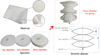 |
Fig. 1 Material and air spring. |
Working information of equipment and instruments.
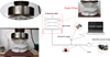 |
Fig. 2 Connection diagram of experiment. |
2.2 Experimental procedure
As depicted in Figure 3, three kinds of air springs were tested in uniaxial compression under nine initial pressure conditions ranging from 0.01 to 0.026 MPa at intervals of 0.002 MPa.
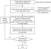 |
Fig. 3 Experimental procedure. |
2.3 Data processing and analytical model
In order to analyze the mechanical properties of air springs and their influence factors, experimental data of various working conditions were processed as follows:
The effect of initial internal pressure on vertical stiffness was compared.
The effect of radius on vertical stiffness was compared.
A universal analytical model for variable vertical stiffness based on geometric parameters and initial internal pressure was established and verified according to the mechanical properties and influence factors of the air spring.
3 Results and discussion
3.1 Mechanical performance under compression
3.1.1 Analysis of influence factors
The results of all experimental conditions show a consistent trend, so a three-chamber air spring working at an initial pressure of 0.010 MPa is taken as an example, as shown in Figure 4. With the increase of displacement, the load, internal pressure and stiffness increase nonlinearly, which shows that there is a positive correlation between the loading and initial pressure.
Number of stack chambers indicates initial volumes of air spring is different, and its effect on mechanical properties is shown in Figure 5. The initial volume, load and stiffness of the air spring are negatively correlated. When initial internal pressure and displacement are constant, the load and stiffness decrease with the increase of initial volume
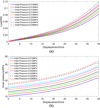 |
Fig. 4 Load and internal pressure during compression. (a) Load curve, (b) internal pressure curve. |
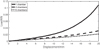 |
Fig. 5 Curves of force and displacement for different air spring. |
3.1.2 Characteristic of loading and unloading processes
Take the three-chamber air spring as an example. The loading and unloading curve with an initial pressure of 0.026 MPa is shown in Figure 6. The physical significance of the area between the curve and the horizontal axis is the energy needed for the air spring to work. Hysteresis in unloading curve may be due to heat exchange, indicating heat flow into the atmosphere, however, the temperature inside the air spring remains constant because of slow compression. During loading, mechanical energy is converted to internal energy of gas, and heat exchange takes place, that is, energy loss. Therefore, the energy during unloading is less than loading. In other words, the vertical stiffness of the air spring decreases slightly during unloading. In this experiment, the enclosed area between the two curves showed an energy loss of 0.1497 KJ.
It can be ascertained that there is a quantitative relationship between vertical stiffness and height, initial pressure and initial volume of air spring. Therefore, in order to describe the variable stiffness of various air springs in general, an analytical model based on geometric parameters and initial pressure is needed to predict the stiffness of any position.
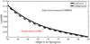 |
Fig. 6 Curves of loading and unloading. |
3.2 Analytical model
3.2.1 General expression of vertical stiffness
A universal analytical model is established based on the Ideal Gas Law [25] expressed as equation (1), referring to the modeling method of automobile suspension air spring [26,27]. When compressed slowly, the air temperature inside the spring can be considered constant. Therefore, the thermodynamic parameter λ is equal to one. The Ideal Gas Law is expressed as equations (1) and (2): (1)
(1)
 (2)
(2)
where v0, v, p0 and p are volume and internal pressure of initial and arbitrary position respectively.
The load of any equilibrium position can be expressed as (3)
(3)
where F, p and Ae are load, internal pressure and effective area.
Combing equations (2) and (3), the equation of load is given: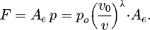 (4)
(4)
Differentiating equation (4) yield universal vertical stiffness of air spring: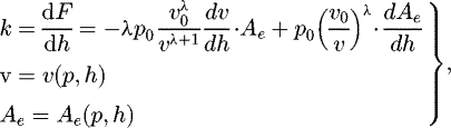 (5)
(5)
where k, h are the vertical stiffness and height of arbitrary equilibrium position.
Volume and effective areas are functions of internal pressure and height of air springs. Through analysis of equation (5), the universal vertical stiffness consists of two items, namely, the volume stiffness and the area stiffness caused by the change of volume and area respectively. From equation (5) it can be seen that the effective area, effective volume and their change rate are the key factors affecting vertical stiffness.
3.2.2 Vertical initial stiffness
Vertical initial stiffness of the air spring implies inherent rigidity, with no load balancing balancing due to the tension between atmospheric pressure, internal pressure and the air-spring chamber. When installed in a mattress system, the air spring slightly compressed due to the gravity of the cushion, there approximately is an equation as v0 = v, the load of air spring at the initial equilibrium position is expressed as equation (6):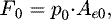 (6)
(6)
where F0, Ae0 are load and effective area of initial equilibrium position.
The radius of the uninflated air spring is expressed in R0, after extended, the surface is curved, as shown in Figure 7a. The key parameters are initial radius R0, assembly height h, and count of chambers n. Each surface in its natural state is a spherical cap surface, as shown in Figure 7b. The volume loss due to welding is negligible. The differences between the air springs in the mattress and the automotive suspensions given in Table 3 indicate that vehicle suspension models are not applicable to a mattress.
The upper surface is approximately spherical cap, the area is expressed as (7)
(7)
where Aa0, Ra, h0 are initial area, radius and height of spherical cap.
Assuming that the material is close to incompressible and the surface of the air spring is unstretchable. When the air spring is not inflated, its surface area is the area of the plane: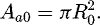 (8)
(8)
Combing equations (7) and (8), the radius of spherical cap is expressed as (9)
(9)
It can be found in equation (9) that the radius of spherical cap is an implicit function of height, satisfying equation  , which indicates there is no one-to-one correspondence between independent variable and dependent variable. Therefore, arbitrary assembly height does not determine the radius of a spherical cap, the volume of chamber should be the function of h0. The volume of the air spring is approximately equal to the sum of volumes of all the air chambers. The volume of half a chamber is expressed as
 (10)
(10)
Combing equations (8) and (10), the volume of air spring can be easily obtained: (11)
(11)
where v0, n are initial volume and sum of chamber of air spring.
At the initial equilibrium position, the equivalent diagram of the force is shown in Figure 8, where T is the tension of the expanded spherical cap. It should be emphasized that Figure 8 shows a two-dimensional ideal force diagram, a cross section through the vertical axis, and all the tensions of all cross sections are distributed relative to the vertical axial symmetrically. In the ideal state, the three-dimensional graph consists of innumerable identical two-dimensional graphs. In addition to that, the tension is only a variable in the process and does not involved in final computation. Therefore, two-dimensional ideal force diagram is used as an analysis object in this paper. The air spring is balanced by tension, atmosphere pressure and internal air pressure. The equilibrium equation is expressed as (12)
(12)
where θ is the angle between the tension and the horizontal line.
Through analysis of geometry, combing equations (9) and (12), θ can be easily calculated: (13)
(13)
Consider two extreme cases:
When the air spring is not inflated, there are two equations: h0 = 0, θ = a cos(1 − 0) = 0.
When the air spring is inflated fully, θ can be calculated by h0 and R0. Through analysis of geometry, the maximum value of 2θ is equal to π and the spherical cap is exactly hemisphere with Ra = h0, substituting that into equation (9) yield the height of spherical cap:
 .
.
Neither of the two extremes is actually possible, consequently, the range of θ and h0 are  ,
,  .
.
Hereto, the parameters of the initial state, R0, h0, n, v0 and Ae0, all can be calculated. When air spring slightly deformed at initial state, there are following equations:  ,
,  , v = v0, Ae = Aeo, p = p0, substituting that into equation (5) and simplifying obtain vertical initial stiffness:
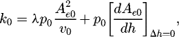 (14)
(14)
where  is rate of change of effective area.
Combing equations (11), (12) and (14), the vertical initial stiffness is given by the equation (15):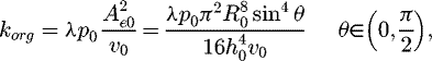 (15)
(15)
where korg, p0, R0, v0 are vertical initial stiffness, initial internal pressure, radius of plane and initial volume of air spring.
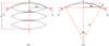 |
Fig. 7 Air spring curved spherical cap (a) Diagram of air spring structure; (b) Force diagram of single curved surface. |
Compare with air spring in automotive suspension.
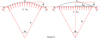 |
Fig. 8 The force diagram of the spherical cap. |
3.2.3 Vertical stiffness of arbitrary equilibrium position
According to equation (5), vertical stiffness of of arbitrary equilibrium position is determined by effective area Ae, effective volume V and their rate of change with height.
(1) Effective area and its rate of change.
The contact surface between the compression plate and the upper surface of the air spring forms a circular plate whose radius increases with the increase of axial displacement. For ease of calculation and analysis, the deformed air spring is roughly seen as a geometry similar to the combination of a cylinder and a volume encased on a curved surface, in which the diameter of the cylinder is the diameter of the contact surface. In order to establish a constant equation, the following assumptions are made:
TPU thin film fabric composite material is nearly in-compressible.
-
Under axial vertical deformation, the surface area of the air spring is invariable and the geometry shape is only changed. Figure 9 shows the approximate shape and force.
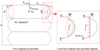
Fig. 9 Diagram of air spring structure and force.
Based on the analysis of Figure 9, the height of spherical cap of n-chamber air spring is expressed as (16)
(16)
where lB, n and h are half height of the chamber, the sum of chambers and the height of air spring at arbitrary equilibrium positions.
According to geometrical axiom, the arc length of each chamber edge is expressed as (17)
(17)
where sa, ra and ψ are arc length, radius of arc and angle between the tension at the edge of and plumb line.
On the basis of the above assumption, the following equation were derived: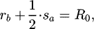 (18)
(18)
where rb, R0 are the radius of contact surface and circular plate of air spring without inflating respectively.
Combing Figures 8 and 9, the equilibrium equations are given: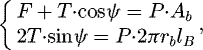 (19)
(19)
where F, T and P are load, tension and internal pressure of air chamber.
The contact area of chamber is calculated by (20)
(20)
Through analytic geometry, yield the following equation: (21)
(21)
Combing equations (19)–(21), the effective area can be easily calculated: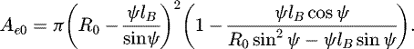 (22)
(22)
The half height of the chamber is obtained by geometric relations: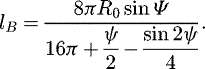 (23)
(23)
Rearrange the equation (23), the mixed trigonometric formula is given: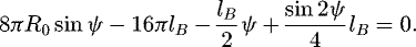 (24)
(24)
Solving formula (24) yield the angle ψ. Differentiating equation (22) and combing equation (16), the rate of change in effective area can be calculated: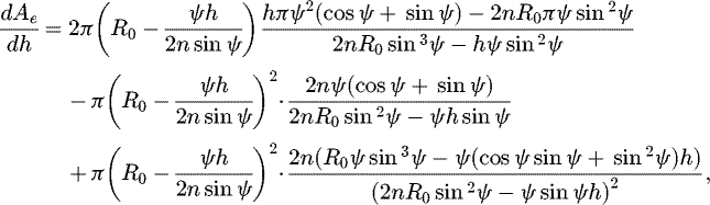 (25)
(25)
where ψ is determined by formula (24).
(2) Effective volume and its rate of change
The effective volume of the approximate geometry consists of two parts, a cylinder below the contact surface, defined as vc, and the volume enclosed by the approximate cambered surface, defined as varc. A single air chamber is shown in Figure 10.
According to the axiom of superficial area of approximate cambered surface, the following equations are obtained: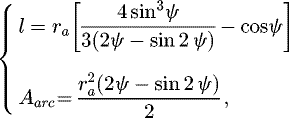 (26)
(26)
where l, Aarc are the distance between the center of approximate cambered surface of air chamber and the plumb line at the edge of the contact surface and the area of the approximate cambered surface of chamber during work.
Combing equations (16) and (26), the effective volume of the air spring is given by equation (27):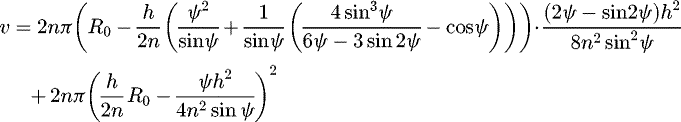 (27)
(27)
Differentiating equation (27), the rate of change of effective volume can be easily obtained: (28)
(28)
Hereto, the vertical stiffness of air spring at any equilibrium position can be calculated by formula in Table 4.
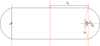 |
Fig. 10 Approximate geometry of single air chamber depressed. |
Calculation formula of variables.
3.3 Verification and modification of the model
3.3.1 Performance of model for initial geometric
The geometric parameters of air spring in the experiment are given in Table 5. To obtain a better understanding of the influence of parameters on vertical initial stiffness, set n = 3, λ = 1 and other initial parameters for equation (15) are respectively shown in Table 6. Vertical initial stiffness values at different values of initial pressure and radius are shown in Figure 11a, b, and the values of initial volume and assembly height for different radii are shown in Figure 11c and d.
According to the analysis of Figure 11a, there is a positive linear correlation between initial vertical stiffness and initial internal pressure when geometric parameters are constant, which means that reducing initial inner pressure can reduce the stiffness of air spring. Through the analysis of Figure 11b, there is a negative non-linear correlation between initial vertical stiffness and radius of plate, which means the increase of radius can decrease stiffness of air spring, consistent with equation (15). Figure 11c indicates that initial volume increases with the increase of radius. Figure 11d demonstrates that the assembly height of an air spring increases proportionally with the increase in radius.
When R0 is equal to 4 cm, the difference between the calculated values and measured values for the height, initial volume and assembly height of the spherical cap are shown in Table 7. The error between them is due to the height assignment of the spherical cap (1.886 cm), which is smaller than the measured values (2 cm), but the error is relatively minor and acceptable.
In order to validate the accuracy of equation (11), set R0 = 4 cm, n = 3, h0 = 2 cm then calculated the initial volume and compared it with the measured value. The results are shown in Table 8, which indicates that the analytical model is quite precise.
Geometric parameters of air spring.
Variable parameter setting.
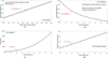 |
Fig. 11 Influence of parameters on stiffness (a) Initial stiffness and initial pressure, (b) Initial stiffness and radius, (c) Initial volume and initial radius, (d) Height and initial radius. |
Calculated and measured values of air spring geometric parameters.
Difference between calculated and measured values of volume.
3.3.2 Performance of model for any equilibrium position
Table 9 shows the predicted loads and intermediate variables for the four height values, as well as the measured loads, and Figure 12 illustrates the difference between the load predictions and the measurements. As can be seen from Table 9 and Figure 12, the error between the calculated and the experimental measurements decreases with the increase of the vertical depressions, and all the calculated values are larger than the measured values, probably due to the approximate geometry, which differs considerably from the actual geometry in small depression but is closer to real geometry when the compression is larger. On this basis, the error is assumed to be a function of height, and a correction function is proposed to modify the model.
Calculation results of arbitrary height of air spring.
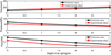 |
Fig. 12 Predicted and experimental values. |
3.3.3 Performance of modified model
As indicated in equation (5) and Figure 12, the load required for compression is a function of the height and initial internal pressure, so the relative error of these two parameters should also be related to the height of air spring. According to experimental data, the error function of initial internal pressure and height can be established by polynomial fitting. The general approach is as follows:
Firstly, the polynomial function of load and height is fitted under nine initial internal pressures, and then the coefficients of the multivariate function are represented by matrix a respectively.
Secondly, the polynomial function between the polynomial coefficients and corresponding nine initial internal pressures is fitted, and then coefficients of polynomial function are represented by matrix b respectively.
Thirdly, matrix a times matrix b and obtain vector c. The elements of vector c are coefficients of the power terms of a polynomial from the highest to the lowest power respectively.
The error function is described as equation (29), and the modification function after twice fitting is presented as equation (30):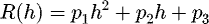 (29)
(29)
 (30)
(30)
where C(r), R(h), Fcor are modifying function, error function and load modified by correction function respectively.
Finally, the modification function is expressed as (31)
(31)
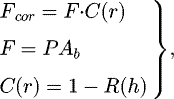
Table 10 shows the fitting results of the correction function, and Figure 13 gives the predicted and measured values for initial internal pressure of 0.020 MPa.
The model for calculation modified by twice fitting can predict load more accurately, and the predicted load and height change trend are in good agreement with the experimental results, which shows that the model is credible in general. There are still some errors in the revised model, and possible sources of error are:
The angle of a transcendental equation can only find the approximate root, not the exact root.
The correction function can not completely eliminate the error after fitting twice, but can only reduce the errors. In the second fitting, the maximum fitting power in this example is 3. The accuracy can be improved by improving fitting ability, but not by much.
Results of modified function fitting.
 |
Fig. 13 Measured values and predicted values with modifying function. |
3.4 The application prospect in mattress
In previous studies, ergonomic mattresses were designed primarily on the basis of body pressure distribution (BPD) at human-mattress interface, which is an indirect indicator of comfort. In addition to BPD, many direct physiological indicators are related to sleep comfort and health, such as oxygen content in blood, heart rate, respiration and spinal alignment, which should be used to help improve mattress comfort. Spinal alignment is an important factor in sleep comfort and health, and abnormal spinal alignment can lead to muscle fatigue and even damage the musculoskeletal system. Conventional mattress support is constant in strength, but sleep behavior is a dynamic processes. Therefore, the mattress can not adjust the support performance according to the sleep posture, which means that the spine is not adequately supported for different sleep behaviors. Although some mattresses with conventional air bags can provide variable stiffness, which is enough to improve the BPD at the human-mattress interface, they fail to enhance spinal alignment during sleep due to the unpredictable deformation.
The application of this novel air spring to ergonomic mattress will provide the possibility to improve spinal alignment. The results of Section 3.1 indicate that this novel air spring with the same geometry size can obtain different stiffness by adjusting initial air pressure, thus satisfying different requirements of different human body parts and different user groups. The method of adjusting the stiffness of air spring is convenient, which provides the possibility for the design of the variable rigidity of mattress. The results of Sections 3.2 and 3.3 indicate that any air springs with different vertical stiffness can be designed and the vertical stiffness at an arbitrary equilibrium position is predictable. Theoretically, the height of this novel air spring subjected to the gravity of the human body can be calculated when installed in a mattress, so the height of air spring below the spine is used to describe the spinal alignment. When spinal alignment needs to be improved, adjust internal pressure of the corresponding air springs below spine and change its vertical stiffness to obtain new height required for normal spinal alignment.
4 Conclusion
In this work, the mechanical properties of air spring and its influence factors were studied, and a general analytical model of variable stiffness has been established according to the Ideal Gas Law and the approximate geometrical parameters of the air chamber. Finally, the analytical models of initial geometry, initial vertical stiffness and the stiffness of arbitrary equilibrium positions were verified and modified. Some valuable conclusions are as follows:
The vertical stiffness of air spring is negatively related to the volume and positively related to initial pressure. The vertical stiffness decreases nonlinearly with the increase of volume and increases linearly with increase of initial pressures.
The calculating model of initial vertical stiffness is established and modified, which provides theoretical guidance for designing air spring by using critical geometric parameters.
In this work, an analytical model of polynomial fitting error is adopted, with an average error of 6.96%.
Research has shown that the air springs have potential applications in providing personalized support and maintaining normal spinal alignment.
The study has two limitations. On the one hand, the density of the material is not taken into account, especially in the analytical model, which may affect the stiffness of air springs when they are made from different materials. On the other hand, only the vertical stiffness of the air spring is studied, and the lateral stiffness may affect its properties during the working process. Therefore, the effect of material density on vertical and lateral stiffness needs further study. Even though, the experimental results and the universal analytical model of variable stiffness air spring still have important theoretical significance for design and engineering application. To sum up, the vertical stiffness model can predict the mechanical properties of the air spring accurately at any height, and provides theoretical guidance for designing the air springs with special stiffness
Conflict of Interest
The authors certify that there is no conflict of interest.
List of symbols
P0: Internal pressure of air spring of initial position (MPa)
p: Internal pressure of air spring of arbitrary position during the working process (MPa)
vo: Volume of air spring of initial position (cm3)
v: Volume of air spring of arbitrary position during the working process (cm3)
h: Height of air spring of arbitrary position during the working process (cm)
Ae: The equivalent support area of the air spring of arbitrary position during the working process (cm2)
Ae0: The equivalent support area of the air spring of initial position (cm2)
R0: The radius of plate of air spring not inflated (cm)
Aa0: The area of plate of air spring not inflated, which is a constant (cm2)
Ra: The radius of spherical cap of air spring (cm)
h0: The height of spherical cap of air spring (cm)
h: The height of air spring of arbitrary position during the working process (cm)
lB: The height of single air chamber of arbitrary position during the working process (cm)
θ: The angle between the tension of the air spring and the horizontal plane in the initial state (rad)
korg: Vertical initial stiffness of air spring of initial position (KN · m−1)
Sa: The arc length of the spherical cap surface through the axis (cm)
ra: The radius of approximate cambered surface of chambers during the working process (cm)
rb: The radius of contact surface (cm)
Ab: The area of contact surface of air spring during the working process (cm2)
l: The distance between the center of approximate cambered surface of air chamber and the plumb line at the edge of the contact surface (cm)
Aarc: The area of the approximate cambered surface of chamber during the working process (cm2)
Ψ: The angle between tension of chamber and plumb line during the working process (rad)
Acknowledgments
Supported by the Postgraduate Research & Practice Innovation Program of Jiangsu Province (KYCX20_0859) and the Project funded by the National First-class Disciplines (PNFD), China.
Author contribution statement
The first author performed the experiment and wrote the article. The second author made an important suggestion on the analysis of experimental data and made important improvements to this study. The third author assisted with the experiments and made the instrument needed for the experiment.
References
- X. Li, B. Zhou, L. Shen et al., Exploring the effect of mattress cushion materials on human-mattress interface temperatures, pre-sleep thermal state and sleep quality, Indoor and Built Environment 1–15 (2020) [Google Scholar]
- X. Li, L. Shen, R. Califano, The comparative study of thermal comfort and sleep quality for innovative designed mattress in hot weather, Science Technology for the Built Environment 26, 1–15 (2010) [Google Scholar]
- V. Verhaert, B. Haex, T. De Wilde et al., Ergonomics in bed design: the effect of spinal alignment on sleep parameters, Ergonomics 54, 169–178 (2011) [Google Scholar]
- Y. Chen, Y. Guo, L. Shen et al., The quantitative effects of mattress and sleep postures on sleep quality, in: International Asia Conference on Industrial Engineering and Management Innovation (IEMI2012) Proceedings: Core Areas of Industrial Engineering, pp. 107–115 (2012) [Google Scholar]
- H. Lee, S. Park, Quantitative effects of mattress types (comfor Table vs. uncomfor Table) on sleep quality through polysomnography and skin temperature, International Journal of Industrial Ergonomics 36, 943–949 (2006) [Google Scholar]
- V. Verhaert, H. Druyts, D. Van Deun et al., Model human-bed interaction:the predictive value of anthropometric models in choosing the correct bed suppor, Work 41, 2268–2273 (2012) [Google Scholar]
- T. Huysmans, B. Haex, T.D. Wilde et al., A 3D active shape model for the evaluation of the alignment of the spine during sleeping, Gait Posture 24, 54–61 (2006) [Google Scholar]
- K. Leilnahari, N. Fatouraee, M. Khodalotfi et al., Spine alignment in men during lateral sleep position: experimental study and model, BioMedical Engineering Online 10, 103 (2011) [Google Scholar]
- S. Rithalia, Assessment of patient support surfaces: principle, practice and limitations, Journal of Medical Engineering Technology 29, 163–169 (2005) [Google Scholar]
- V. Verhaert, D. Van Deun, J. Verbraecken et al., Smart control of spinal alignment through active adjustment of mechanical bed properties during sleep, Journal of Ambient Intelligence and Smart Environments 5, 369–380 (2013) [Google Scholar]
- M. Saegusa, H. Noguchi, G. Nakagami et al., Evaluation of comfort associated with the use of a robotic mattress with an interface pressure mapping system and automatic internal air-cell pressure adjustment function in healthy volunteers, Journal of Tissue Viability 27, 146–152 (2018) [Google Scholar]
- M. Malbrain, B. Hendriks, P. Wijnands et al., A pilot randomised controlled trial comparing reactive air and active alternating pressure mattresses in the prevention and treatment of pressure ulcers among medical ICU patients, Journal of Tissue Viability 19, 7–15 (2010) [Google Scholar]
- O. Ezeamuzie, V. Darian, U. Katiyar et al., Intraoperative use of low-profile alternating pressure mattress for prevention of hospital acquired pressure injury, Perioperative Care and Operating Room Management 17, 100080 (2019) [Google Scholar]
- D. Beeckman, B. Serraes, C. Anrys et al., A multicentre prospective randomised controlled clinical trial comparing the effectiveness and cost of a static air mattress and alternating air pressure mattress to prevent pressure ulcers in nursing home residents, International Journal of Nursing Studies 97, 105–113 (2019) [Google Scholar]
- S. Tsuchiya, A. Sato, E. Azuma et al., The effectiveness of small changes for pressure redistribution; using the air mattress for small changes, Journal of Tissue Viability 25, 135–142 (2016) [Google Scholar]
- K.H. Lee, Y.E. Kwon, H. Lee et al., Active body pressure relief system with time-of-flight optical pressure sensors for pressure ulcer prevention, Sensors (Basel) 19 (2019) [Google Scholar]
- V. Verhaert, H. Druyts, D. Van Deun et al., Model human-bed interaction: the predictive value of anthropometric models in choosing the correct bed suppor, Work 41, 2268–2273 (2012) [Google Scholar]
- V. Verhaert, H. Druyts, D. Van Deun et al., Estimating spine shape in lateral sleep positions using silhouette-derived body shape models, International Journal of Industrial Ergonomics 42, 489–498 (2012) [Google Scholar]
- R. Xie, C. Ulven, B. Khoda, Design and manufacturing of variable stiffness mattress, Procedia Manufacturing 26, 132–139 (2018) [Google Scholar]
- C. Dealey, Pressure-relieving devices: the use of pressurerelieving devices (beds, mattresses and overlays) for the prevention of pressure ulcers, Journal of Tissue Viability 13, 186–187 (2003) [Google Scholar]
- C.Y. Chai, O. Sadou, P.R. Worsley et al., Pressure signatures can influence tissue response for individuals supported on an alternating pressure mattress, Journal of Tissue Viability 26, 180–188 (2017) [Google Scholar]
- J.M. Still, J. Wilson, C. Rinker et al., A retrospective study to determine the incidence of pressure ulcers in burn patients using an alternating pressure mattress, Burns 29, 505–507 (2003) [Google Scholar]
- J. Smardzewski, New construction of mattress springs, Materials Design 49, 318–322 (2013) [Google Scholar]
- J. Smardzewski, Models of hybrid springs for ergonomic seats and mattresses, Drvna industrija 64, 9–18 (2013) [Google Scholar]
- L. Xu, Mathematical modeling and characteristic analysis of the vertical stiffness for railway vehicle air spring system, Mathematical Problems in Engineering 2020, 1–12 (2020) [Google Scholar]
- L. Xu, Research on nonlinear model and dynamic characteristics of lateral stiffness of vehicle air spring system, Advances in Mechanical Engineering 12, 2072262133 (2020) [Google Scholar]
- X. Chen, S. Han, T. Luo, D. Guo, Investigation of sliding mode control for nonlinear suspension systems with state estimation, Mechanics Industry 21, 611 (2020) [Google Scholar]
Cite this article as: Y. Chao, L.M. Shen, M.P. Liu, Mechanical characteristic and analytical model of novel air spring for ergonomic mattress, Mechanics & Industry 22, 37 (2021)
All Tables
All Figures
|
Fig. 1 Material and air spring. |
| In the text | |
|
Fig. 2 Connection diagram of experiment. |
| In the text | |
|
Fig. 3 Experimental procedure. |
| In the text | |
|
Fig. 4 Load and internal pressure during compression. (a) Load curve, (b) internal pressure curve. |
| In the text | |
|
Fig. 5 Curves of force and displacement for different air spring. |
| In the text | |
|
Fig. 6 Curves of loading and unloading. |
| In the text | |
|
Fig. 7 Air spring curved spherical cap (a) Diagram of air spring structure; (b) Force diagram of single curved surface. |
| In the text | |
|
Fig. 8 The force diagram of the spherical cap. |
| In the text | |
|
Fig. 9 Diagram of air spring structure and force. |
| In the text | |
|
Fig. 10 Approximate geometry of single air chamber depressed. |
| In the text | |
|
Fig. 11 Influence of parameters on stiffness (a) Initial stiffness and initial pressure, (b) Initial stiffness and radius, (c) Initial volume and initial radius, (d) Height and initial radius. |
| In the text | |
|
Fig. 12 Predicted and experimental values. |
| In the text | |
|
Fig. 13 Measured values and predicted values with modifying function. |
| In the text | |
Current usage metrics show cumulative count of Article Views (full-text article views including HTML views, PDF and ePub downloads, according to the available data) and Abstracts Views on Vision4Press platform.
Data correspond to usage on the plateform after 2015. The current usage metrics is available 48-96 hours after online publication and is updated daily on week days.
Initial download of the metrics may take a while.