| Issue |
Mechanics & Industry
Volume 25, 2024
Advanced Approaches in Manufacturing Engineering and Technologies Design
|
|
|---|---|---|
| Article Number | 24 | |
| Number of page(s) | 11 | |
| DOI | https://doi.org/10.1051/meca/2024017 | |
| Published online | 04 October 2024 | |
Regular Article
Mechanical behavior of macroscopic interfaces for 3D printed multi-material samples made of dissimilar materials
1
“Gheorghe Asachi” Technical University of Iasi, Department of Machine Manufacturing Technology, Blvd. Dimitrie Mangeron 59A, Iasi, 700050, Romania
2
Ansbach University of Applied Science, Faculty of Technology, Residenzstraße 8, Ansbach, 91522, Germany
* e-mail: This email address is being protected from spambots. You need JavaScript enabled to view it.
Received:
11
August
2023
Accepted:
31
May
2024
Abstract
The development of 3D printing technologies has introduced new possibilities in producing multi-material parts, and Fused Filament Fabrication (FFF) is one of these technologies. Typically, multi-material parts are made of different blends of the same material, also known as multi-color 3D printing, or from materials with good chemical compatibility. Conventionally, a simple face-to-face bonding interface between part components and chemical bonding between thermoplastics define the mechanical performance of multi-material components. In this regard, the paper aimed to investigate the contact interface strength of multi-material specimens using a geometric approach. Therefore, several geometrical interfaces, such as dovetail, omega, T-shape, and others, were used to interlock pars of low-compatibility thermoplastic polymers, styrene-acrylonitrile acrylic (ASA), and thermoplastic polyurethane (TPU). In the case of one of these interfaces, modeling by the finite element method was resorted to obtain additional information regarding the processes that develop at the interface level between the two components of the joint during the tensile loading. The results showed that the macroscopic interlocking interfaces significantly improved the mechanical properties of the multi-material specimens.
Key words: Fused filament fabrication / multi-material / interlocking geometry / contact interface / heterogeneous materials
© V. Ermolai et al., Published by EDP Sciences 2024
 This is an Open Access article distributed under the terms of the Creative Commons Attribution License (https://creativecommons.org/licenses/by/4.0), which permits unrestricted use, distribution, and reproduction in any medium, provided the original work is properly cited.
1 Introduction
Fused Filament Fabrication (FFF) is a material extrusion technology that uses molten thermoplastic forced through a nozzle to build parts additively. First, a three-dimensional mesh is needed, then processed in the machine's software (the slicing tool) and sliced in layers with a defined thickness. Multiple parameters must be adjusted based on the part's requirements (e.g., material, use), such as filament width and thickness, infill pattern and degree, deposition speed, and extrusion temperature [1].
Due to the good dimensional accuracy and material sourcing, FFF has become one of the most used 3D printing technologies. FFF can use standard materials (polylactic acid), engineering-grade (e.g., ASA), and high-performance polymers (e.g., polyetherimide) [2].
Multi-extrusion 3D printers allow more freedom in designing complex models and building orientation during printing by using soluble or low-compatibility materials for support structures. They offered new opportunities to manufacture multi-color and multi-material components. A multi-material part requires a distinct mesh for each material and preferably chemically compatible polymers (e.g., ABS-ASA) with similar melting ranges. Depending on the part's design, the materials can be deposited side by side, layered, or both [3].
Lopes et al. proposed a methodology to evaluate the chemical affinity of PLA, TPU, and PET samples by implementing multiple transitions between materials through a zebra cross-sample design [3]. They showed that conventional but joint multi-material interfaces are not enough to provide good mechanical properties.
Ribeiro et al. evaluated the performance of contact interfaces for multi-material samples with high-compatibility, PLA-PLA, and low-compatibility materials, PLA-TPU, for tensile strength [4]. They concluded that macroscopic interfaces are needed to achieve good mechanical properties.
Lumpe et al. researched the tensile strength of specimens made from combinations of materials that presented different contact interfaces. They appreciated that the tensile strength is dependent both on the geometric parameters of the interface and on the nature of the materials in the specimens' components [5].
Experimental research on the joint quality between additively manufactured samples made of two materials was performed by Kluczyński et al. [6]. Experimental results revealed that test samples with an overlapping interface have higher strength than the ones without.
Charlon et al. have appreciated that the properties of the adhesion strength between filaments depend significantly on the temperature of the polypropylene beads [7]. They found that an increase in the nozzle temperature from 170 °C to 180 °C leads to a 145% increase in adhesion strength.
Lepoivre et al. considered that the microporosities resulting from the reduced coalescence between filaments contribute to the deterioration of the mechanical properties of the parts made by FFF [8]. Coalescence depends on the molten polymer's viscosity and surface tension. It was proposed that a coupling of a semi-analytical model with a 2D heat transfer finite element be used to simulate the coalescence of the molten material.
A study of the influence of contact interface geometry on the mechanical properties of multi-material samples made of two PLA blends was carried out by Ermolai et al. [9]. The results showed that the contact interface with an overlap degree between the mating bodies influences the tensile properties. Later, some research on the tensile strength of omega and dovetail joints was carried out by Mihalache et al. [10]. The results of the experimental tests were used to establish empirical mathematical models capable of highlighting the influence exerted by the interface dimensional features on the magnitude of the maximum braking force for samples made of low-compatibility polymers. In another work, the problem of characterizing multi-material samples from the point of view of tensile and impact behavior was addressed, the samples being made of two dissimilar materials [11].
Chen et al. [12] analyzed some recent advances in the 3D printing of functional ceramic devices. They appreciated that the so-called xenogeneic materials, which include ceramics and metals, should be compatible with multi-material 3D printing technologies.
Nazir et al. analyzed multi-material additive manufacturing, considering the design, properties, and applications of 3D printing of polymers and metal materials [13]. They found there are limitations in software packages, processes, and joining mechanisms, especially at the level of multi-material interfaces.
The problem of modeling using the finite element method of the crashworthiness behavior of some multi-layered multi-materials was addressed by Rozycki et al. [14]. In this sense, they proposed a new methodology for characterizing the bi-phase model. Later, finite element modeling of the behavior of multi-layered multi-materials was also used by Coutellier and Rozycki [15] to show that in the case of composite materials, an asymmetrical tension/compression behavior of the plies can be highlighted.
Cao et al. [16] found that using multiple materials in a part's structure could reduce its manufacturing cost or weight. They proposed an optimization method that uses mathematical modeling to consider the inter-material boundaries.
Merklein et al. have appreciated that joining dissimilar high-strength materials is a problem that must be addressed when manufacturing multi-material lightweight structures [17]. They analyzed different procedures that can be used in this sense.
Benarbia et al. proposed a multi-physics model to predict the adhesion degree using semi-crystalline polymers (i.e., poly-aryl-ether-ketone) for the FFF process [18]. He considered it possible to improve the adhesion degree between the deposited filaments by using the model.
The examination of some articles published in recent years about the manufacturing of multi-material parts using 3D printing processes has highlighted the fact that there is, first of all, a tendency to diversify solutions for joining the components of multi-material parts by taking into account the fields in which such parts will be used. On the other hand, investigations have also been undertaken concerning the mechanical properties of multi-material parts, aiming to improve the behavior of multi-material components when subjected to different mechanical stresses.
This paper aims to present the results of tensile and impact resistance tests in the case of samples made of dissimilar materials, considering a geometric perspective. An approach to the problem through the finite element method allowed information on the behavior of a multi-material specimen in tension to be obtained. The experimental research used six macroscopic contact interfaces and three interlocking ways of the multi-material samples' components. The resulting geometries were subjected to a systematic analysis using the Taguchi method.
2 Material and methods
2.1 Samples' preparation
In the context of this article, the research focused on the strength of the adhesion mechanism at the interface level for parts made of low-compatibility polymers. The research carried out so far found that due to the heterogeneity of the ASA and TPU polymers, the regular butt joint interfaces (Fig. 1a) cannot be used. An overlap between the mating bodies and an alternated deposition, like a woven structure (Fig. 1b), is necessary to ensure the integrity and strength of the resulting interfaces. However, due to the lack of affinity between materials, the overall interface strength is given by the fiction forces resulting from the intimate contact of the stacked layers. Such structures were considered benchmark interfaces for the macroscopic interfaces and had a 0.4 mm overlap (Fig. 1b) between the samples' mating bodies.
For this research, the multi-material samples were printed using a black ASA produced by the Dutch company FormFutura, Apollo X, and a natural TPU Hardeness+ material from the Spanish company Smart Materials 3D. Before printing, the filaments were dried in a Memmert Model 500 oven at temperatures of 75 °C for ASA and 65 °C for TPU for 4 h without the introduction of outside air. Since both polymers are hydrophobic, the filament spools were kept in an enclosure (i.e., a PolyBox) to maintain constant humidity throughout printing.
A geometrical joining approach can compensate for the poor adhesion between ASA and TPU. Thus, instead of coalescence (i.e., the interpenetration of polymer chains) resulting from the intimate contact between the extruded filaments during healing (Charlon et al., 2021; Lepoivre et al., 2021; Benarbia et al., 2023), a macroscopic, physical interface holds the parts' components together. However, the dimensions of the macroscopic contact interfaces were limited by the specimen format for the tensile and impact tests (see Fig. 2). A constraint on the contact geometries was used to ensure that a minimum of four perimeters (i.e., 1.6 mm) were printed for each component of the 3D-printed part. The dimensions and the way of joining the surfaces of the two components corresponding to the number of six distinct geometries of contact between the two material components can be seen in Figure 2.
The samples were printed with the same values of the input factors in the printing process using an Ultimaker 3 printer (manufactured by the Dutch company Ultimaker). Since the two materials are sensitive to temperature variations, the printing was done in a closed environment. The glass bed was coated with a thermally activated DimaFix adhesive (manufactured by the Dutch company FormFutura) to prevent the parts from detaching or warping due to thermal shrinkage. The specimens were removed from the enclosure after the deposition plate had cooled to a temperature of 40 °C (Tab. 1).
The specimens' macroscopic interfaces were designed based on specimen 1B of ISO 257:2 for the tensile test and 1 of ISO 179:1 for the impact test. The interfaces have a 4 mm base and height for the male body and a 1.6 mm sidewall thickness (i.e., four perimeters) for the female body. The other dimensions of the interlocking geometries were constrained based on the profile specifics. Figure 2 presents a preview of the resulting design of the interfaces based on Contact geometry, Interlocking side, and Overlap.
Tensile tests were performed with a universal testing machine, Instron 4411, with a 5kN load cell at a speed of 5 mm/s in a laboratory environment with a temperature of 23 °C and 55% humidity. The impact strength was determined using a Zwick 5102.21 Charpy impact test machine using a 2J pendulum. The impact tests were performed for unnotched samples with the pendulum striking in the flatwise orientation, according to the ISO 179-12010 standard. All samples were manufactured using an Ultimaker 3 printer in a closed environment after reaching 40 °C. Five replicates were printed for each run covered in the experimental plan (see Tab. 2) for the tensile test and ten samples for the impact test.
 |
Fig. 1 Multimaterial bond preview: (a) Regular interface vs. (b) 0.4 mm Overlapped interface. |
 |
Fig. 2 Macroscopic interfaces resulted from the Taguchi L18 design matrix used for the samples of the tensile (1B of ISO 527-2:2012) and Charpy impact (1 of ISO 179-1:2010). |
Constant and variable parameters of the multi-material specimens.
The Taguchi L18 (61 & 32) mixed experimental matrix and the values of the average results of the tensile and Charpy impact tests (σ represents the normal stress, ε, the specific strain, and acU, the impact resistance).
2.2 Finite element modeling of interface behavior in the tensile test
After the experimental runs, the finite element method was used to simulate the fracture of one of the macroscopic interfaces. The aim was to highlight the stress distribution as the samples' components moved along the load direction, achieving a similar shape after the fracture. It was chosen Ansys's explicit dynamics module for our analyses.
The materials properties were available via the Total Materia database for TPU graded according to ASTM standard (U.S.A.) [19] and introduced in the Engineering Data materials library. Experimental tests recorded the following for our chosen sample, namely R3_OA_Pyz&yz: 8.05 MPa for tensile stress at break, 1.48% for elongation at break, and 1.19 mm for tensile deformation at break. This information was added for TPU in Engineering Data.
The contacts section received two frictional contacts with an average of 1 [20] of the friction coefficient, as presented in Figure 3. No joint and body interaction was added.
Mesh-wise, a 1 mm element size was chosen for each contact with a multizone method applied to both samples, which imposes hexagonal elements for the mapped mesh type. Free mesh type inside multizone was not allowed. It resulted in 1149 nodes and 3891 elements (Fig. 4a). Conditions-wise, it was applied for fixed support at one of the sample's ends and a force of 0.42 kN according to experimental tests at the opposite face of the second sample (Fig. 4b).
Analysis settings include explicit dynamics integration, which uses diagonals for its characteristic dimensions. Euler domain definition is program controlled and scoped to all bodies. Tracking is available by the body. Erosion controls stop the analysis when a geometric strain limit of 100% is met.
Results are similar to those recorded after experimental tests (Fig. 5b for sample 3.2). It was chosen to highlight the equivalent elastic strain, which peaks at 0.016 mm (Fig. 5a). As soon as the fracture occurs, the strain dissipates along the entire length of both samples. Probes can be used to capture each stage of the process, thus giving valuable insight into it. More refinement may be necessary before using the results the authors acknowledge.
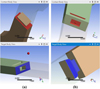 |
Fig. 3 FEM-related graphical representations of contacts: (a) frictional contact between horizontal faces for both samples, (b) frictional contact between linkage faces for both samples. |
 |
Fig. 4 FEM setup: (a) graphical representation of mesh; (b) graphical representation of used conditions. |
 |
Fig. 5 FEM results: (a) Graphical representation of equivalent elastic strain distribution, (b) image of samples after experimental tests. |
2.3 Design of experiments
The resulting samples' multi-material interfaces corresponded to a mixed Taguchi L18 type experimental design matrix, with three independent variables, one variable on six levels, and two variables with three levels of variation. The selected independent variables were the Contact geometry, the Interlocking side, and the Overlap of the sample components (Tab. 1).
The geometric interface profile variable considers the shape of the interlocking profiles. The considered geometrical profiles were named omega adapted (OA), dovetail (DT), dovetail adapted (DTA), T shape (TS), T shape adapted (TSA), and arrow shape (AS). The upper part of the circular profile was removed for the omega profile to ensure the same height of 4 mm for all profiles (Fig. 2). Compared to the original ones, the other adapted profiles added a shoulder for the DTA and a connection radius for the TSA profile. These adaptations were intended to increase the parts' elongation capacity.
The interlocking side parameter has three levels and controls the coupling method of the specimens' components. The first level, Full yz (Fyz), corresponds to contact over the entire thickness of the sample (i.e., 4 mm). In this way, the interlocking profile of the ASA component is contained by the TPU component only on the side surfaces. The second level, Partial yz (Pyz), provides conditions for the interlock geometry to include contact only at the core of the specimen (i.e., 2 mm of the 4 mm total thickness). This way, the ASA component is enveloped by the TPU body. The last level, Partial yz and xz (Pyz&xz), gives an interlock similar to the previous level's (the profile's base is wrapped around the TPU component); however, the last 2 mm of the profile's height intersects with the mating body throughout the thickness of the specimen of 4 mm.
The last considered variable was the overlap degree between the samples' components, set at 0.0-0.2 mm. Since ASA and TPU polymers will not fuse, the maximum level of 0.2 mm is expected to improve the strength and elongation capacity due to the frictional force generated between the alternated layers (Fig. 1b). Theoretically, the frictional force has an opposite direction to the load force.
A total of 18 macroscopic geometrical interfaces resulted based on the considered variables levels and the Taguchi experimental matrix (see Fig. 2). For each parameter's configuration (see Tab. 2), five replicates were printed for tensile and ten for the Charpy impact tests. In total, 285 samples were printed and tested.
3 Results
Following tensile and impact testing of the specimens, average values and standard deviations for normal stress, specific strain, and impact resistance were calculated. The resulting values are presented in Table 2. A preview of normal stress (σ)-specific strain (ε) diagrams corresponding to some samples tested following the experimental plan can be seen in Figure 6.
The clustered column chards describe the average values for tensile stress, strain at peak, impact resistance of the 18 experimental runs, and standard deviations referred to the benchmark interface (see Fig. 1b). On the one hand, the best results regarding the tensile properties were obtained by the R10, described by an FT interface with Fyz interlocking and 0.2 mm overlap. The R10 interface configuration showed an average tensile stress of 10.22 ± 1.11 MPa and 1.77 ± 0.57% of strain. On the other hand, the best results for the impact energy absorption were recorded for the R16 joint, printed with an AS interface in a Fyz interlocking and 0.2 mm overlap. The R16 interface configuration showed an average impact resistance of 4.91 ± 1.52 kJ/m2. However, by analyzing the same plots, we can observe that the macroscopic interfaces are improving the mechanical properties compared to the simple overlapped interface.
Regarding the samples' behavior during testing, they presented a similar failure mode in each group (e.g., OA, DT). Furthermore, breaking behavior was also comparable between the interfaces' interlocking sides. However, four breaking patterns were observed during the testing. In the first scenario, the parts break in the ASA side before the mid-plane (Figs. 8a, Figs. 8b). In the second scenario, the fracture occurs in the TPU printed component (Figs. 8d, Figs.8f). These fracture mechanisms show that the resulting macroscopic interfaces are more robust than the TPU component filament bonds (i.e., between perimeters and rasters). The third failure mode shows a combined behavior, summarizing the first two scenarios above. Thus, the fracture of the components occurs in the interlocking area of the geometric interface where both materials fail (Fig. 8c). The last scenario was observed only for parts printed with parameterization R13 (with T-shaped interface, Fyz interlock, and 0.1 mm overlap). They show a visible deformation of geometrical interface features. The part's bodies slide to the point where the lateral geometries of the TPU component deform, grip, and compress the wide area of the ASA T-profile (Fig. 8e). This interface failure behavior was recorded for three of the five tested specimens. In the Charpy impact tests, the samples' geometric interfaces failed according to the first three modes obtained in the tensile tests.
As presented above, an optimal geometric interface must be chosen according to the type of mechanical loading the part is subjected to. Thus, T-shaped (TS) and adapted T (TSA) interfaces are preferable for increased stress or strain capacity. As for the impact energy absorption, the most resistant is the arrow-shaped (AS) profile.
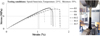 |
Fig. 6 Stress-strain curves of R3, R6, R8, R12, R14, and R18. |
 |
Fig. 7 The average tensile stress, strain at peak, and impact strength of the 18 interface configurations refer to a regular contact interface with a 0.4 mm overlap. |
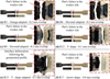 |
Fig. 8 Preview of the failure mode of the macroscopic contact interfaces. |
4 Discussion
After the mechanical tests, the raw data was used to determine the average stress and strain at peak and impact strength for each group of specimens, including the benchmark samples. The average results were analyzed graphically using clustered column charts (Fig. 7). The results are relevant, presenting minor standard deviations. Overall, stress averages display a standard deviation in the range (0.31, 1.69 MPa) and the strain within the interval (0.02, 0.61%). As for the impact strength, the standard deviation is in the (0.35, 1.92 kJ/m2) range.
All six macroscopic interlocking geometries registered increased load capacity and maximum yield during the tensile tests. Based on the tensile properties presented in Figure 7, the weakest of the considered designs was the arrow shape with Pyz interlocking. The average results show a relatively small variation between the studied interface geometries and the interlocking sides for the rest of the specimens. Overall, the best results for the tensile strength were obtained by the R10 configuration with TS profile, Fyz interlocking, and 0.2 mm overlap between mating bodies. As for the yield, the TS and TSA interfaces with Fyz interlocking showed the best results.
The macroscopic interfaces showed increased energy absorption capacity compared to the benchmark samples, and the best results were obtained for the Fyz interlocking side for most of the interface shapes (except DTA). A possible reason for these results is the larger cross-section area of the interface in the sample's male body (i.e., ASA). Analyzing the main effects plots (Fig. 9) shows that the highest energy absorption is achieved by the AS interface, followed by OA with Fyz interlocking and a reduced influence of the overlap factor.
Statistical processing of the mechanical test results was carried out using Minitab 21 software. The influence of the main factors was analyzed using factorial plots and the Pareto charts of the standardized effects (Fig. 9). Further, the significance of the factors was appreciated based on the analysis of the variance of the results (F-Values and P-Values from Tab. 3). The analysis was performed with a risk factor α of 0.05 (Fig. 9).
Table 3 and Figure 9 show that the significance of the main factors differs depending on the response variable. The most important factor for stress is the overlap between mating bodies, followed by the interlocking side and the contact geometry. As for strain and impact strength, the most significant factors are the interlocking side, the contact geometry, and a statistically insignificant overlap contribution. Overall, the contact geometry and the interlocking side have the most significant influence on the mechanical properties of the ASA-TPU samples.
The Ovp factor has the highest influence on the stress response and the lowest on the strain and impact strength. The overlap between the mating bodies increases the areas of horizontal contact by alternating the two materials at the level of the boundaries. The resulting woven structure increases the maximum load capacity even if the materials are dissimilar.
Ribeiro et al. studied the mechanical performance of multi-material 3D printed samples made of PLA and TPU with three macroscopic interfaces, U-shape, Dovetail, and T-shape, the latest showing the best results [4]. Similar results were obtained in this study, proving that macroscopic interfaces are a feasible solution for multi-material printing with dissimilar polymers. FFF can produce multi-material parts in a single run. However, the combinations of polymeric materials are limited to chemical compatibility, and identifying an adequate macroscopic interface depends on the mechanical load.
 |
Fig. 9 Main effects plots of tensile stress, strain, impact strength, and Pareto charts of the standardized effects for the ABS-TPU samples (α-level risk). |
F-value and P-value for the main factors are based on the ASA-TPU specimens' analyzed responses.
5 Conclusion
The literature review highlighted the importance of identifying suitable macroscopic interface designs when 3D printing multi-material parts of various categories of thermoplastic polymers.
By defining a macroscopic interface between parts' mating bodies, the limitations of materials' compatibility are reduced. The influence of six macroscopic interfaces was studied with three interlocking solutions. An overlap degree between the three levels was also considered between the mating bodies.
Tensile and impact test results show that the mechanical properties are significantly improved by the macroscopic interfaces regardless of their shape when compared to the benchmark samples. All three considered variables are significant, but the overall significance depends on the analyzed response variable. The contact geometry and overlap are the most beneficial for tensile strength. As for the tensile strain and impact resistance, the contact geometry and interlocking side are more significant.
The experimental research results showed that the highest tensile strength values were obtained in the case of a T-shaped interface (10.22 MPa). In contrast, the maximum values of average specific strain corresponded to T-shaped and T-shaped-adapted interfaces (1.77%). The maximum impact resistance was obtained for the arrow-shaped interface (4.91 kJ/m2).
The use of macroscopic contact interfaces provides new possibilities regarding multi-material part manufacturing. However, further research should be done to explore new interface shapes and simplify their design process to extend their implementation on complex parts.
Acknowledgments
The authors thank the Plastic Processing Laboratory of the Ansbach University of Applied Science for providing their research facilities.
Funding
The Article Processing Charges for this article are taken in charge by the French Association of Mechanics (AFM).
Conflicts of interest
The authors declare no conflicts of interest.
Data availability statement
The data presented in this study are available on request from the corresponding author.
Author contribution statement
Conceptualization, V. Ermolai; methodology, L. Slătineanu; statistical analysis, V. Ermolai, A.I.I. and G. Nagîț; formal analysis, A. Hrițuc and R.C. Stavarache; investigation, V. Ermolai and M.A. Boca; FEM analysis, A.M. Mihalache; resources, A. Sover; writing—initial draft preparation, V. Ermolai; writing—review and editing, A.M. Mihalache and L. Slătineanu; visualization, M.A. Boca.; supervision, A. Sover, G.Nagîț and L. Slătineanu. All authors have read and agreed to the published version of the manuscript.
References
- S.S. Krishnanand, A. Nayak, M. Taufik, Generation of tool path in fused filament fabrication, in: R. Agrawal, J.K. Jain, V.S. Yadav, V.K. Manupati, L. Varela (Eds.), Recent Advances in Smart Manufacturing and Materials. Lect. Notes in Mech. Eng. Springer, Singapore, 2021 [Google Scholar]
- A. Dey, I.N. Roan Eagle, N. Yodo, A review on filament materials for fused filament fabrication, J. Manuf. Mat. Process. 5, 69 (2021) [Google Scholar]
- L.R. Lopes, A.F. Silva, O.S. Carneiro, Multi-material 3D printing: the relevance of materials affinity on the boundary interface performance, Addit. Manuf. 23, 45–52 (2018) [Google Scholar]
- M. Ribeiro, O. Sousa Carneiro, A. Ferreira da Silva, Interface geometries in 3D multi-material prints by fused filament fabrication, Rapid Prototyp. J. 25, 38–46 (2019) [CrossRef] [Google Scholar]
- T.S. Lumpe, J. Mueller, K. Shea, Tensile properties of multi-material interfaces in 3D printed parts, Mater. Des. 162, 1–9 (2019) [CrossRef] [Google Scholar]
- J. Kluczyński, L. Śnieżek, A. Kravcov, K. Grzelak, P. Svoboda, I. Szachogłuchowicz, O. Franek, N. Morozov, J. Torzewski, P. Kubeček, The examination of restrained joints created in the process of multi-material FFF additive manufacturing technology, Materials 13, 903 (2020) [CrossRef] [Google Scholar]
- S. Charlon, J. Le Boterff, J. Soulestin, Fused filament fabrication of polypropylene: influence of the bead temperature on adhesion and porosity, Addit. Manuf. 38, 101838 (2021) [Google Scholar]
- A. Lepoivre, A. Levy, N. Boyard, V. Gaudefroy, V. Sobotka, Coalescence in fused filament fabrication process: thermo-dependent characterization of high-performance polymer properties, Polym. Test. 98, 107096 (2021) [CrossRef] [Google Scholar]
- V. Ermolai, A. Sover, G. Nagîț, Influence of contact geometry over the filament bond of polylactic acid blends, Conf. Ser.: Mater. Sci. Eng. 1235, 012004 (2021) [Google Scholar]
- A.M. Mihalache, V. Ermolai, A. Sover, G. Nagit, M.A. Boca, L. Slatineanu, A. Hrituc, O. Dodun, M.I. Ripanu, Tensile behavior of joints of strip ends made of polymeric materials, Polymers 14, 4990 (2022) [CrossRef] [PubMed] [Google Scholar]
- V. Ermolai, A. Sover, M.-A. Boca, A. Hrițuc, L. Slătineanu, G. Nagîț, R.-C. Stavarache, Mechanical behaviour of macroscopic interfaces for 3D printed multi-material samples, MATEC Web Conf. 368, 3 (2022) [Google Scholar]
- H. Chen, L. Guo, W. Zhu, C. Li, Recent advances in multi-material 3D printing of functional ceramic devices, Polymers 14, 4635 (2022) [CrossRef] [PubMed] [Google Scholar]
- A. Nazir, O. Gokcekaya, K.M. Masum Billah, O. Ertugrul, J. Jiang, J. Sun, S. Hussain, Multi-material additive manufacturing: a systematic review of design, properties, applications, challenges, and 3D printing of materials and cellular metamaterials, Mater. Des. 226, 11166 (2023) [Google Scholar]
- P. Rozycki, D. Coutellier, X. Ni, E. Haug, New functionnalities for pam crash™ multi-layered multimaterial element, Proceedings of the Euro-PAM'98 Conference, Tours, France, October 1998 [Google Scholar]
- D. Coutellier, P. Rozycki, Multi-layered multi-material finite element for crashworthiness studies, Compos. − A: Appl. Sci. 31, 841–851 (2000) [CrossRef] [Google Scholar]
- J. Cao, K. Cai, P.F. Wang, D. Yan, J. Shi, Multiple materials layout optimization in a layered structure, Mech. Ind. 17, 404 (2016) [CrossRef] [EDP Sciences] [Google Scholar]
- M. Merklein, M. Jäckisch, C.-M. Kuball, D. Römisch, S. Wiesenmayer, S. Witusche, Mechanical joining of high-strength multi-material systems − trends and innovations, Mech. Ind. 24, 16 (2023) [CrossRef] [EDP Sciences] [Google Scholar]
- A. Benarbia, V. Sobotka, N. Boyard, C. Roua, Fused filament fabrication: Numerical adhesion modeling suitable for semicrystalline polymers, Material Forming − ESAFORM 2023, Mater. Res Proc. 28, 139–142 (2023) [Google Scholar]
- Total materia,available: xx https://www.totalmateria.com/TM_materials.aspx?st=ASTM&gr=1&ty=640&cl=1159 &sc=744&db=2&LN=VN,accessed: 27.07.2023 [Google Scholar]
- C. Wang, A. Hausberger, M. Berer, G. Pinter, F. Grün, T. Schwarz, Fretting behavior of thermoplastic polyurethanes, Lubricants 7, 73 (2019) [CrossRef] [Google Scholar]
Cite this article as: V. Ermolai, A. Sover, M. Andrei Boca, A. M. Mihalache, A. I. Irimia, Ad. Hrițuc, L. Slătineanu, G. Nagîț, R. C. Stavarache, Mechanical behavior of macroscopic interfaces for 3D printed multi-material samples made of dissimilar materials, Mechanics & Industry 25, 24 (2024)
All Tables
The Taguchi L18 (61 & 32) mixed experimental matrix and the values of the average results of the tensile and Charpy impact tests (σ represents the normal stress, ε, the specific strain, and acU, the impact resistance).
F-value and P-value for the main factors are based on the ASA-TPU specimens' analyzed responses.
All Figures
|
Fig. 1 Multimaterial bond preview: (a) Regular interface vs. (b) 0.4 mm Overlapped interface. |
| In the text | |
|
Fig. 2 Macroscopic interfaces resulted from the Taguchi L18 design matrix used for the samples of the tensile (1B of ISO 527-2:2012) and Charpy impact (1 of ISO 179-1:2010). |
| In the text | |
|
Fig. 3 FEM-related graphical representations of contacts: (a) frictional contact between horizontal faces for both samples, (b) frictional contact between linkage faces for both samples. |
| In the text | |
|
Fig. 4 FEM setup: (a) graphical representation of mesh; (b) graphical representation of used conditions. |
| In the text | |
|
Fig. 5 FEM results: (a) Graphical representation of equivalent elastic strain distribution, (b) image of samples after experimental tests. |
| In the text | |
|
Fig. 6 Stress-strain curves of R3, R6, R8, R12, R14, and R18. |
| In the text | |
|
Fig. 7 The average tensile stress, strain at peak, and impact strength of the 18 interface configurations refer to a regular contact interface with a 0.4 mm overlap. |
| In the text | |
|
Fig. 8 Preview of the failure mode of the macroscopic contact interfaces. |
| In the text | |
|
Fig. 9 Main effects plots of tensile stress, strain, impact strength, and Pareto charts of the standardized effects for the ABS-TPU samples (α-level risk). |
| In the text | |
Current usage metrics show cumulative count of Article Views (full-text article views including HTML views, PDF and ePub downloads, according to the available data) and Abstracts Views on Vision4Press platform.
Data correspond to usage on the plateform after 2015. The current usage metrics is available 48-96 hours after online publication and is updated daily on week days.
Initial download of the metrics may take a while.