| Issue |
Mechanics & Industry
Volume 25, 2024
|
|
|---|---|---|
| Article Number | 33 | |
| Number of page(s) | 11 | |
| DOI | https://doi.org/10.1051/meca/2024032 | |
| Published online | 16 December 2024 | |
Original Article
Correlation analysis between coiling tension and the sleeve's hoop stress
Department of Mechanical Engineering, Sunmoon University, Asan, Chungnam, Republic of Korea
* e-mail: This email address is being protected from spambots. You need JavaScript enabled to view it.
Received:
6
July
2024
Accepted:
6
November
2024
Abstract
The coiling process, crucial for winding long sheets of consistent thickness, often encounters challenges due to deformation induced by pressure and frictional forces on the inner mandrel and sleeve. This necessitates precise stress calculations to ensure operational safety within elastic deformation limits. This study proposes a novel mathematical model to accurately predict stress distribution in the sleeve's hoop direction. The mathematical model is modified by applying a correction factor, derived from an enhanced analytical solution based on the Lame equation, specifically tailored to address coiling stress during prior elastic deformation. Validation of the proposed analytical solution was carried out using finite element analysis through the ABAQUS model. This validation process revealed variations in stress within the sleeve's hoop direction corresponding to different coiling tensions. Furthermore, parametric analysis highlighted a correlation between increased coiling tension and higher frictional forces exerted by the first layer of the steel coil on the sleeve, resulting in discernible variations in hoop stress based on sleeve radius and coiling tension. The key innovation lies in the application of the correction factor to the Lame equation, enabling the derivation of stress results consistent with finite element analysis, even under arbitrary coiling tension and sleeve radius inputs. This analytical solution not only holds promise for predicting the behavior of various thick-walled cylinders produced through different manufacturing processes involving coiling but also facilitates integration with monitoring systems to mitigate slumping during steel rolling operations, all while minimizing computational burden.
Key words: Coiling / stress analysis / lame equation / analytical solution / finite element analysis / least-squares method
© Y. Park, Published by EDP Sciences 2024
 This is an Open Access article distributed under the terms of the Creative Commons Attribution License (https://creativecommons.org/licenses/by/4.0), which permits unrestricted use, distribution, and reproduction in any medium, provided the original work is properly cited.
Glossary
i (=1 to N): The current coiling layer
r: The radial position from the sleeve to the coil
σT: Coiling tension
t: Strip's thickness
µ: Frictional coefficient
Ri,man: The inner radius of the mandrel
Ro,man: The outer radius of the mandrel
Ri,sleeve: The inner radius of the sleeve
Ro,sleeve: The outer radius of the sleeve
Ri,coil: The inner radius of the coil including 1st to i-1th coiling layer
Ro,coil: The outer radius of the coil including 1st to i-1th coiling layer
pi,man: The pressure on the inner radius of the mandrel
po,man (=pi,sleeve): The pressure on the outer radius of the mandrel(=the inner radius of the sleeve)
po,sleeve (=pi,coil): The pressure on the outer radius of the sleeve(=the inner radius of the coil including 1st to i-1th coiling layer)
po,coil: The pressure caused by the i th coiling, on the outer radius of the coil including 1st to
i-1th: coiling layer
σr,sleeve: The radial stress of the sleeve
σθ,sleeve: The hoop stress of the sleeve
σr,coil: The radial stress of the coil
σθ,coil: The hoop stress of the coil
A, C: The unknown factors in the Lame equation calculated by the outer and inner pressure
α: The correction factor in the modified Lame equation
pii: The coefficients in the surface function of the correction factor α
g(θT,i, αj): The stress result of the analytical solution
gi: The stress result of the finite element analysis model
1 Introduction
Coiling process is wound in a state where coiling tension is forced on the steel sheet to make a uniform spiral coil. Coiling tension is a primary factor determining the shape and deformation of the coil. When the coiling tension is excessive, excessive radial stress is generated inside the sleeve and strip coil, resulting in the slumping of the material's coil and severe deformations [1]. Conversely, insufficient coiling tension can lead to failure in coil formation due to the uncoiling phenomenon of the strip coil and slippage between the strip layers. In the case of thin steel sheets, coiling conditions significantly affect the coil's status, necessitating additional measures to prevent excessive deformations. For instance, in thin steel sheets, the steel sheet is wound while the sleeve is inserted on the mandrel. This is because as the thickness of the steel sheet decreases, the reaction force of the radial direction of the coil to maintain the shape against the external pressure caused by coiling decreases. Severe deformation occurs in the steel sheet where the mandrel and the steel sheet are not in direct contact locally. Accurate prediction of the stress distribution occurring in the sleeve and coil according to the coiling process conditions is directly related to more coil stacking and equipment lifespan, and various predictive studies have been conducted. To predict these deformations, previous studies have suggested analytical solutions based on cylinder theory, solving equations with boundary conditions under certain assumptions, without the need for numerical iteration to verify the stress distribution. With the development of computational technology, finite element analysis has started to replace analytical solutions due to its higher accuracy. However, solving numerical iterations in non-linear contact problems using implicit methods takes longer compared to analytical solutions. This is the reason why I aimed to develop the analytical solution.
Firstly, a coiling process, where a steel sheet is wound directly onto a mandrel, was studied assuming a two-dimensional plane stress problem [2]. The study suggested the formula for radial and hoop stress calculations using the pressure values applied to the inside and outside of the hollow cylinder, and the formula was verified by estimating the strain of the coil with a strain gauge. The stress calculation analytical solution was developed by previous work [3,4]. The N-1th steel sheet is laminated on the mandrel, the pressure value from the coiling tension is applied to the Nth steel sheet when the Nth steel sheet is wound, and the hollow structure formed by the mandrel and the N-1th steel sheet is wound accordingly. This lamination calculates and accumulates pressure between cylinders through force fitting. This basic model is developed by analysing the coil's internal stress distribution through the coupling between thick and thin cylinders [5]. The elastic stress model is expanded to three dimensions to calculate the stress distribution according to the flatness [6]. Applied studies such as model improvement for stress calculation have been carried out [7]. A stress analysis in conjunction with multicylinder interference fitting [8–10] was also conducted to calculate the stress for mandrel-sleeve-coil coiling introduced for coiling thin steel sheets, and a finite element analysis model for the structure was developed [11]. Especially considering that experimental approaches are impractical for acquiring stress distributions among inter-layers of coils due to high pressure accumulation during coiling, the finite element analysis model, verified by comparing theoretical analysis results from the Lame equation [12], can be applied to various engineering problems. In the previous work, a parametric study, such as the stress-concentrated area change by changing the coiling conditions was performed [13]. By improving the assumptions of the bending and coiling pressure of the steel sheet applied to the developed analytical solution, it was enhanced to an analytical solution that can accurately express the stress within the range of elastic deformation [14]. It was confirmed that the hoop stress applied to the sleeve is a friction force caused by the coiling tension, and there is a limitation in calculating it with the existing Lame equation. It was confirmed that the correction factor that can compensate for this should be reflected in the stress calculation equation. This calculation is important to specify coiling conditions, such as the number of coiling layers and coiling tension, to ensure that the sleeve remains within elastic deformation.
In this study, a correction factor function for coiling tension was derived to enhance the accuracy of calculating hoop stress in the sleeve. Using the previous finite element analysis model, a parametric study was conducted by changing coiling conditions and arranging stress distributions of the sleeve and the coil. Especially when various coiling tensions were applied, the same analysis as that used in the finite element analysis model was employed to derive the correction factor in the Lame equation for each coiling tension and stress result. Finally, the correction factor was improved to enhance the accuracy of the analytical solution, thereby increasing its calculation accuracy through functionalization.
2 Computational modeling
2.1 Analytical solution of the coiling stress distributions with a mandrel and sleeve
Figure 1 is a flow chart for calculating the analytical stress solution's coiling stress based on elastic deformation proposed in the previous study. By using the pressure by the coiling tension applied to the stacked Nth coil, the problem of the simultaneous equations of the interlayer pressure based on the theory of force fit between the cylindrical mandrel, the sleeve, and the 1st to N-1th coils is solved as well as the problem between each cylindrical part (Fig. 2). After calculating the applied pressure, it is added to the existing accumulated pressure and applied to the Lame's equation to calculate the internal part's stress. The Nth coil is used to calculate the coiling tension and bending stress to calculate the radial and hoop stresses. When the N+1th coil is stacked, it is reflected in the 1st to Nth coil cylinders, the same as the previous step. The interlayer pressure and stress is then iteratively calculated. This rule repeats until the coiling finishes.
To derive the calculation formula in the third step of Figure 1, “Calculate coiling pressures among the boundary layers”, based on the current i-th coil being stacked, pressure is applied to the boundaries between three different material layers: the mandrel, the sleeve, and the accumulated 1st to (i − 1)th coils. Organizing the boundary pressures from the innermost to the outermost, they can be listed as pi,man, po,man, pi,sleeve, po,sleeve, pi,coil, po,coil. Here, the subscript i denotes the inner side, o denotes the outer side, and “man,” “sleeve,” and “coil” represent the mandrel, sleeve, and coil, respectively. Given that po,man and pi,sleeve, as well as po,sleeve and pi,coil, are on the same boundary surface and therefore have the same values, the boundary pressures can ultimately be simplified to four: pi,man, po,man(=pi,sleeve), p1(=po,sleeve=pi,coil), p2(=po,coil). These four unknown pressures can be calculated through the force fit described by equations (1) and (2). Although only two equations are presented, examining the mechanical structure reveals that pi,man has a pressure value of 0, and p2 can be defined through the pressure formula (Eq. (3)) applied by the i-th stacked coil, allowing for the calculation of the remaining two unknown pressures.
See equation (1), (2) next page.
 (1)
(1)
 (2)
(2)
 (3)
(3)
where po,man, pi,man, νman, Eman, Ro,man and Ri,man are the outer pressure, the inner pressure, Poisson' ratio, modulus of elasticity, the outer radius and the inner radius of the mandrel, p1, νsleeve, Esleeve and R1 are the outer pressure, Poisson' ratio, modulus of elasticity and the outer radius of the sleeve, and p2, νcoil, Ecoil, R2 are the outer pressure, Poisson' ratio, modulus of elasticity, the outer radius of the coil.
By accumulating the boundary pressure values calculated from the tension of the newly stacked coil and applying them to equations (4) and (5), the radial and hoop stresses of the sleeve mentioned in the fourth step can be derived. These equations can be formulated into a system of simultaneous equations by equating the pressures acting on the inner and outer boundaries of the sleeve to the radial stress, allowing for the calculation of the unknowns A and C. However, as mentioned in previous research, the hoop stress of the sleeve is not accurately predicted by this equation due to effects such as friction, necessitating an improved formula [14]. Based on this analysis model, the correction factor for accurate hoop stress calculation of the sleeve proposed in the introduction is applied to the constant term of the Lame's equation (Eq. (6)). Supposing the coiling condition and the arbitrary correction factor are given, the radius and hoop stress generated in the sleeve and coil can be calculated. Nevertheless, the stress in the sleeve hoop direction is intensively calculated, and the stress is corrected for the change in the coiling tension by comparing it with the results of the finite element analysis. Therefore, the correction factor should be identified to improve the accuracy of the analytical solution.
 (4)
(4)
 (5)
(5)
 (6)
(6)
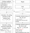 |
Fig. 1 Flow chart of calculating coiling stress. |
 |
Fig. 2 Schematic diagram of coiling. |
2.2 Finite element analysis model of the coiling stress distributions with a mandrel and sleeve
The ABAQUS finite element analysis model for mandrel-sleeve-coil stress calculation that was established in the previous study was used [14] (Fig. 3). The finite element analysis model has two parts; the sleeve and the strip that are deformable. Two parts have linear elastic material property with density, modulus of elasticity and Poisson's ratio. The mandrel was regarded as a rigid body by giving kinematic coupling the rotational center and the inner radius of sleeve. In other words, the inner radius of the sleeve and the centre of rotation were defined as rigid bodies in the coupling module. According to the centre of rotation, a constant rotational motion of 4π rad/sec was applied in the counter-clockwise direction without deformation. The sleeve has an equally spaced element in both the hoop and radial directions. On average, the aspect ratio of the sleeve's mesh is about 1.34. Since the strip has five elements in the thickness direction, the stress distribution for bending can be checked, and in the longitudinal direction, the bias function is used so that the nodes between the coiling layers having the same angular phase can contact each other in the process of stacking the strip into a coil. As a result, the size of elements increases as the element is placed on the right side of the strip. In the meshing of the strip, selecting an ideal aspect ratio for the strip's mesh is challenging. In the actual winding process, assuming the thin stainless steel strip with a length of 1,486 meters is wound around the sleeve used in this analysis, it must be wound approximately 384 times. The issue arises because, compared to the strip's length, the thickness is extremely small, at just 0.001 meters. When dividing the mesh, if user sets square mesh elements with an aspect ratio of 1:1 between the thickness direction and the strip's length direction, and place 5 elements in the thickness direction, about 7,430,000 elements will be generated along the length of the strip. This dramatically increases the degrees of freedom, requiring significant computational resources. Additionally, due to the continuous contact between the sleeve and the coil, as well as self-contact between the coil layers, and the accumulation of large displacements, the nonlinear analysis becomes highly complex, making it difficult to predict results in a short time. Fortunately, a previous study [11] utilized high-performance computational resources to apply these conditions to an actual finite element analysis model. By comparing it to the analytical model developed for calculating stress in the sleeve and strip using interference fitting and the Lame's equation, the study derived an appropriate analysis model from the perspective of mesh quality, including aspects such as aspect ratio, Jacobian, warpage, and skewness. The results showed that the stress distribution in both models was consistent, and even after numerous layers were stacked, the stress distribution remained within the expected range. Based on this, the mesh used in the previous study was applied in the current analysis. The goal of this research is to modify the previous analytical model to more accurately predict the stress acting on the sleeve. Rather than using the original strip length of 1486 meters, as in the previous study, this model reflects a length of 54.538 meters, assuming the strip is wound into 20 layers. The same meshing criteria mentioned earlier, with respect to the thickness and length directions, were applied. The mesh type of the sleeve and the strip is 4-node bilinear, reduced integration with hourglass control (CPS4R) [15].
About the constraint, interaction, and boundary condition, the left edge of the strip is constrained on the uppermost node of the outer sleeve. Regarding contacts among the sleeve and the strip, the hard contact condition was applied to the vertical direction. The penalty method with a friction coefficient of 0.05 was applied to the tangential direction. About external forces, coiling tension is applied to the right edge of the strip with the opposite direction of the sleeve's rotation to wind the coil tightly. Table 1 presents the coiling conditions that are used in the finite element analysis.
About the finite element solver, dynamic implicit method was chosen. The solver has initial increment size 1 × 10⁻⁵ and minimum increment size 1×10⁻¹⁵, and non-linear effect of large deformation was applied.
Coiling conditions.
3 Parametric study of the computational model according coiling conditions
3.1 The internal stress of the sleeve according to coiling tension
The stress calculation results of the analytical solution and the finite element analysis model were compared to verify the validity of the analytical solution. Regarding the analytical solution, the coil is expressed as a hollow cylinder. The radial and hoop stresses of a constant magnitude are calculated regardless of the sleeve's hoop position. However, different results can be obtained depending on the hoop position, as both the sleeve and coil internal stress distributions caused by coiling the spiral coil with the discontinuous connection where the sleeve and the strip contacts start in the finite element analysis model (Fig. 4). For example, the internal stress of the sleeve is small and hard to figure out the difference along the circumferential position in the upward side of Figure 4 compared to the magnitude of the internal stress of the coil. However, upon temporarily removing the coil from the stress plot of the assembly, a noticeable variation in stress can be observed from red to blue along the circumferential position. This variation is attributed to stress concentration at the contact point between the sleeve and the coil. Accordingly, the stress at the location where the stress concentration area's influence was insignificant, including the opposite side of the contact starting point where the stress concentration occurred, was analysed by comparing the result to the analytical solution. The results of radial and hoop stresses of the sleeve were compared according to the radial position from the inner radius to the outer radius of the sleeve in the further parametric studies regarding the coiling conditions.
 |
Fig. 4 Radial stress of the sleeve during coiling: (a) radial stress distribution including the sleeve and the strip; (b) radial stress distribution of the sleeve without the strip. |
3.2 Sleeve's hoop stress calculation correction factor according to coiling tension
In this section, a case analysis was conducted to derive the proposed stress correction factor (Eq. (6)) to increase the accuracy of calculating the hoop stress compared the model without the correction factor. The unknowns A and C in σθ,sleeve can be determined by using the boundary conditions the outer and inner pressure by using the Lame equation regarding σr,sleeve [16]. When the coils are stacked on the sleeve, an interlayer frictional force is applied together with pressures from the coiling tension. Therefore, compression and torsion coexist in the sleeve. In the case of radial stress due to pressure, the Lame equation can be sufficiently expressed. However, there is a limitation in expressing the hoop stress due to torsion. Therefore, a correction factor was introduced to calculate the hoop stress. The correction factor greatly influenced by torsion includes the interlayer friction coefficient and the coiling tension. First, as a result of checking how the change in the friction coefficient affects the hoop stress and the correction factor, the blue-dotted distribution, the red-dotted distribution and the black-dotted distribution have no difference in the hoop stress of the inner radius and the outer radius of the sleeve (Fig. 5). In other words, It was confirmed that there was no significant effect on the variations in the hoop stress distribution, and was removed from the design variable in the parametric study. Therefore, the values of the frictional coefficient between sleeve and strip, and self-frictional coefficient of strip were applied as 0.05 referring to the previous work [14].
Additionally, when examining the factors that may affect the hoop stress of the sleeve, changes in the sleeve's material and shape can naturally result in differences in the stress distribution. However, sleeves are typically manufactured in a hollow form and made from alloy steel that is reinforced against fatigue, with mechanical properties similar to those of carbon steel, making the influence of these factors minimal. Moreover, changes in the material and shape of the steel sheet layered onto the sleeve could affect the calculation of hoop stress. However, this issue can be easily resolved by understanding the reason for using the sleeve. In the case of thick steel strip obtained through hot rolling processes in steel mills, the strip is typically layered directly onto the mandrel without the need for a sleeve, similar to how a core is used in a roll of tissue. On the other hand, for the thin steel strip produced through cold rolling, as dealt with in this study, the steel cannot withstand the pressure from continuous layering if it is layered directly onto the mandrel. Thus, a sleeve is placed in the center before winding. When a certain amount of layering is achieved on the sleeve, the sleeve can become deformed, which can affect the quality of the coil. Therefore, it is necessary to predict the internal deformation state to ensure layering is done only to the point where the sleeve does not deform. For the steel sheet addressed in this study, with a thickness of 3 mm or less, the second moment of area is small, meaning that bending deformation occurs very easily without significant material strength effects. When winding tension is applied, the bending and tension occur directly under the applied force, making the influence of other factors extremely rare.
Accordingly, a finite element analysis applying various coiling tensions was performed, and the Lame equation correction factor of the analytical solution that can provide the same distribution as the sleeve hoop stress in the finite element analysis was derived and functionalized (Tab. 2).
At this time, the least-squares method was applied between the stress result g(σT,j,αk) of the analytical solution according to the arbitrary correction factor αk and the stress result σj of the finite element analysis to derive the correct result value of the correction factor for each coiling tension σT,j. Thus, the most likely value αi was derived (Eq. (7)) [17,18].
 (7)
(7)
 |
Fig. 5 Sleeve's stress distributions according to a frictional coefficient. |
The overview of case studies.
4 Results and discussion
4.1 The internal stress of the sleeve according to coiling tension
Figure 6 shows the hoop stress σ&z.Theta; according to the radial position between the sleeve's inner diameter and outer diameter, depending on the coiling tension in the finite element analysis result. As the coiling tension increases, the hoop stresses have high absolute values in the both sub-figures in Figure 6. In the case of the outer diameter of the sleeve, it has a higher hoop stress than the inner diameter due to torsion caused by coiling the steel sheet. Additionally, compression in the hoop direction due to torsion increases as the magnitude of the coiling tension increases. It was also confirmed that the correction factor α is a dependent variable for the radial position r, as the hoop stress change rate differs according to the sleeve radial position whenever the coiling tension changes.
 |
Fig. 6 Stress distributions of the sleeve. |
4.2 Sleeve's hoop stress calculation correction factor according to coiling tension
In this section, based on the sleeve's hoop stress results for each coiling tension, the functionalization of the correction factor α was performed. Unlike the original plan, in the previous section, as the hoop stress results changed according to the radial position of the sleeve, the coiling tension σT and the radial position r were treated as independent variables. Through GNU Octave's code using the least-squares method, the surface function of equation (8) was obtained, and the result of visualizing it is shown in Figure 7. By synthesizing results from previous studies [14] and actual parameter analyses, it has been established that the hoop stress generated internally lies between the inner and outer stress values of the sleeve. According to the Lame equations, this stress distribution is inversely proportional to the square of the radial position. Based on the stress values at the sleeve boundaries, a method was applied to estimate the internal state. Specifically, by creating a function that provides appropriate coefficients for each radial position based on the applied tension values when various tensions are applied, it becomes possible to determine the trends of these values, which are bounded by the maximum circumferential stress at the outer sleeve and the minimum circumferential stress at the inner sleeve, across a range of 30 MPa to 150 MPa (Tab. 3). If the trends of these values can be identified, it becomes feasible to characterize the internal behavior and function. Figure 7 illustrates the correction factor data obtained through the least-squares method for the sleeve boundaries, which represents a function that continuously expresses the correction coefficients for the Lame equations based on different coiling tensions. Regarding the distribution trend of the correction coefficient, it can be seen that the higher the coiling tension, the closer the values are to the outer diameter of the sleeve, resulting in a lower correction coefficient. The developed stress correction factor function was able to replicate the same stress result as the hoop stress of each sleeve radial position obtained in the finite element analysis when an arbitrary coiling tension was applied within the existing stress calculation model (Fig. 8).
 (8)
(8)
where α is the correction factor, r is the radial position of the sleeve, and the coefficient p00, p10, p01, p20, p11, p30 and p21 are 1.157, −8.573 × 10⁻³, −2.061 × 10⁻², 3.745 × 10⁻³, −1.227 × 10⁻³, −1.521 × 10⁻⁴, and 2.189 × 10⁻³ respectively.
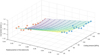 |
Fig. 7 Correction factor, α according to coiling tension, σT, and the radial position of the sleeve, r. |
The optimum value of correction factor α(σT, r).
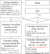 |
Fig. 8 Flow chart of calculating the coiling stress with the correction factor, α. |
5 Conclusions
In this study, a correction factor was derived to enhance the accuracy of calculating hoop stress in the sleeve during mandrel-sleeve-coil coiling, focusing on elastic deformation. By applying the Lame correction equation with a correction factor, tailored to different coiling tensions, the model's usability was improved through functionalization. Utilizing finite element analysis stress results under various coiling tensions, the maximum correction factor using the least-squares method was derived. The resulting analytical model, incorporating the correction factor, offers a more precise calculation of internal deformation in the sleeve and strip, accounting for traction induced by coiling tension and torsional effects. This model holds promise for applications such as optimizing coiling processes and developing real-time coiling simulators. Future work will involve creating a simulator that predicts real-time coiling states by integrating a dynamics analysis model of the entire coiling process with the stress calculation model developed in this study.
Acknowledgments
This work was supported by the Sunmoon University research grant of 2023.
Funding
The author received financial support for the Sunmoon University research grant of 2023, authorship and publication of this article.
Conflicts of interest
The author declares no potential conflicts of interest with respect to the research, authorship and publication of this article.
Data availability statement
All data generated or analyzed during this study are included in the present article.
Author contribution statement
The author, Yonghui Park, confirmed contribution to the paper as follows primarily; study conception and design, computational modeling, analysis and interpretation of results, draft manuscript preparation. In addition, the author reviewed the results and approved the final version of the manuscript.
References
- B. Anderssen, N. Fowkes, R. Hickson, M. McGuinness, Analysis of coil slumping, in Proceedings of the 2009 Mathematics and Statistics in Industry Study Group, Wollongong, Australia (2009), p. 90–108 [Google Scholar]
- R.B. Sims, J.A. Place, The stresses in the reels of cold reduction mills, Br. J. Appl. Phys. 4, 213 (1953) [CrossRef] [Google Scholar]
- J. Case, A.H. Chilver, Strength of Materials and Structures: An Introduction to the Mechanics of Solids and Structures, 2nd edn. (Elsevier, Amsterdam, 2013) [Google Scholar]
- I. Doghri, D. Chandrasekharaiah, Mechanics of deformable solids: linear and nonlinear, analytical and computational aspects, Appl. Mech. Rev. 54, B105 (2001) [CrossRef] [Google Scholar]
- S. Yanagi, S. Hattori, Y. Maeda, Analysis model for deformation of coil of thin strip under coiling process-flatness change of thin strip during coiling process I, J. Jpn. Soc. Technol. Plast. 39, 51 (1998) [Google Scholar]
- W.W. Park, D.K. Kim, Y.T. Im, H.C. Kwon, M.S. Chun, Effects of processing parameters on elastic deformation of the coil during the thin-strip coiling process, Met. Mater. Int. 20, 719 (2014) [CrossRef] [Google Scholar]
- Y.Q. Wang, L.I. Li, X.C. Yan, Y.X. Luo, L. Wu, Modeling of stress distribution during strip coiling process, J. Iron Steel Res. Int. 19, 6 (2012) [CrossRef] [Google Scholar]
- A.C. Ugural, S.K. Fenster, Advanced Strength and Applied Elasticity, 4th ed. (Prentice-Hall Inc, New Jersey, 2003) [Google Scholar]
- T.J. Chung, Applied Continuum Mechanics (Cambridge University Press, Cambridge, 1996) [Google Scholar]
- T. Sato, Four Concentric Cylinders with Prescribed Axial Strain (Thiokol Corporation, Utah, 1974) [Google Scholar]
- Y.H. Park, K.T. Park, S.Y. Won, W.K. Hong, H.C. Park, Stress analysis model of strip winding system with a sleeve for a coil of thin stainless steel, J. Iron Steel Res. Int. 24, 1 (2017) [CrossRef] [Google Scholar]
- K.T. Park, Y.H. Park, H.C. Park, S.Y. Won, W.K. Hong, Stress analysis of cold rolled strip coiling process, Trans. Korean Soc. Mech. Eng. 41, 409 (2017) [Google Scholar]
- K.T. Park, H.C. Park, Effects of design parameters and tension on behavior of a coil using finite element analysis, J. Iron Steel Res. Int. 25, 883 (2018) [CrossRef] [Google Scholar]
- Y.H. Park, K.T. Park, C.W. Lee, W. Shi, Improvement of the coiling stress calculation model for a mandrel-sleeve-coil, Adv. Mech. Eng. 14, 1 (2022) [Google Scholar]
- D. Hibbit, B. Karlsson, P. Sorensen, Getting Started with ABAQUS-Version (6.5)-Plasticity in Ductile Metals (Inc. Hibbit, Karlsson and Sorensen, Pawtucket, 2005) [Google Scholar]
- A.H. Slocum, Precision machine design: macromachine design philosophy and its applicability to the design of micromachines, in Proceedings of IEEE Micro Electro Mechanical Systems, in Travemunde, Germany (1992), p. 37–42 [Google Scholar]
- J.W. Eaton, D. Bateman, S. Hauberg, Gnu Octave (Network theory Ltd., Godalming, 1997) [Google Scholar]
- A. Quarteroni, F. Saleri, P. Gervasio, Scientific Computing with MATLAB and Octave Volume (Springer, Berlin, 2006) [Google Scholar]
Cite this article as: Y. Park, Correlation analysis between coiling tension and the sleeve's hoop stress, Mechanics & Industry 25, 33 (2024), https://doi.org/10.1051/meca/2024032
All Tables
All Figures
|
Fig. 1 Flow chart of calculating coiling stress. |
| In the text | |
|
Fig. 2 Schematic diagram of coiling. |
| In the text | |
 |
Fig. 3 Finite element analysis model [14]. |
| In the text | |
|
Fig. 4 Radial stress of the sleeve during coiling: (a) radial stress distribution including the sleeve and the strip; (b) radial stress distribution of the sleeve without the strip. |
| In the text | |
|
Fig. 5 Sleeve's stress distributions according to a frictional coefficient. |
| In the text | |
|
Fig. 6 Stress distributions of the sleeve. |
| In the text | |
|
Fig. 7 Correction factor, α according to coiling tension, σT, and the radial position of the sleeve, r. |
| In the text | |
|
Fig. 8 Flow chart of calculating the coiling stress with the correction factor, α. |
| In the text | |
Current usage metrics show cumulative count of Article Views (full-text article views including HTML views, PDF and ePub downloads, according to the available data) and Abstracts Views on Vision4Press platform.
Data correspond to usage on the plateform after 2015. The current usage metrics is available 48-96 hours after online publication and is updated daily on week days.
Initial download of the metrics may take a while.