| Issue |
Mechanics & Industry
Volume 20, Number 6, 2019
|
|
|---|---|---|
| Article Number | 612 | |
| Number of page(s) | 7 | |
| DOI | https://doi.org/10.1051/meca/2019045 | |
| Published online | 26 November 2019 | |
Regular Article
A calculation method of thermal deformation for double helical gear
School of Mechanical Engineering, University of Jinan, Jinan 250022, PR China
* e-mail: This email address is being protected from spambots. You need JavaScript enabled to view it.
Received:
19
October
2018
Accepted:
23
January
2019
Abstract
Thermal deformation caused by gear transmission is an important factor causing gear impact, vibration and partial load. Gear modification can effectively improve the effects caused by thermal deformation. The calculation of thermal deformation is the first problem to be solved before gear modification. This paper takes double helical gear as the research object and a calculation method of thermal deformation is proposed. Firstly, temperature of instantaneous meshing points on the tooth surface are measured and these discrete temperature values are fitted by the linear interpolation. Calculation formula of temperature distribution along gear radial direction is introduced. Combining both, tooth surface temperature field is obtained. Secondly, equation of tooth surface for double helical gear before and after thermal deformation is derived according to the tooth surface temperature field. Finally, an example is given. Compared with the given modification of thermal deformation, the calculated thermal deformation is almost equal to theoretical value. On this basis, the thermal deformation of double helical gear considering the installation error and machining error is calculated, which provides a theoretical basis for thermal deformation modification of double helical gear.
Key words: Thermal deformation / double helical gear / temperature field / modification / error
© AFM, EDP Sciences 2019
1 Introduction
Thermal deformation caused by gear transmission is an important factor causing gear impact, vibration and partial load. Gear modification is an effective way to improve its transmission performance [1–4]. The calculation of thermal deformation provides a basis for gear modification.
When calculating thermal deformation of gear, the temperature field should be determined first. It consists of two parts: the gear body temperature and the instantaneous surface temperature (it is also known as flash temperature). The instantaneous surface temperature depends on the body temperature. The traditional calculation of gear body temperature has the experience formula of ISO flash temperature criterion and integral temperature criterion, but the calculation results cannot determine the temperature distribution of gear teeth, and cannot meet the requirements of deformation calculation. Bobach [5] analyzed the regularities of distribution of temperature field inside the gear teeth. Qiu Liangheng [6] used finite element method to calculate and analyze the temperature and thermal deformation of gear. The calculated results can be used as the basis for analyzing and calculating the lubricating oil film thickness and gear tooth profile modification. Gong Xiansheng [7] applied the theories of Hertz contact, tribology, gear engagement and heat transfer, established the finite element analysis model of the temperature field of gear body, and obtained the steady-state temperature field of the planetary gear tooth. Patir [8] and Wang [9] used finite element method to estimate the temperature field of spur gear tooth, and made theoretical analysis and numerical calculation on dynamic load and oil film thickness. Li [10] proposed the concept of non-involute characteristics. When the temperature of gear is changed, the theoretical tooth profile and the practical tooth profile are not superposition. On this basis, Wang [11] proposed a method for calculating the thermal deformation of helical gear.
Present experimental measurement technology can get the meshing point temperature value of gear. Reference [1] gives a simplified formula for temperature distribution along gear radial direction, which can be applied in engineering. Based on this, the specific process of the paper is shown in Figure 1.
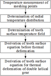 |
Fig. 1 Flow diagram for calculation of thermal deformation of double helical gear. |
2 Determination of tooth surface temperature field
Figure 2 showed the schematic diagram of determining tooth surface temperature distribution. The temperature values of instantaneous meshing point 1, 2, …, n are firstly measured and fitted. Together with the given temperature formula along gear radial direction, temperature field is determined.
 |
Fig. 2 Schematic diagram of determining tooth surface temperature distribution. |
2.1 Measurement and fitting of temperature of instantaneous meshing points on the tooth surface
Using the infrared technology, the miniature thermocouple automatic recorder and the simulated heat source infrared technology to measure the temperature of instantaneous meshing points on the tooth surface. The temperature curve in the direction of the meshing line along the tooth width is obtained by the linear interpolation.
2.2 Temperature distribution along gear radial direction
Reference [1] gives a simplified formula for temperature distribution along gear radial direction, which can be applied in engineering. The formula can be expressed as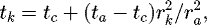 (1)where rk
is the radius of gear arbitrary circle k, its temperature is tk
; tc
is the temperature of gear center; ra
is the radius of addendum circle, its temperature is ta
; The unit of temperature in the formula is °C.
(1)where rk
is the radius of gear arbitrary circle k, its temperature is tk
; tc
is the temperature of gear center; ra
is the radius of addendum circle, its temperature is ta
; The unit of temperature in the formula is °C.
2.3 Determination of tooth surface temperature field
According to the fitting curve along meshing points and formula (1), the temperature ta of addendum circle along tooth surface can be obtained. And then through formula (1), the temperature of arbitrary point can be calculated, i.e., the tooth surface temperature field is determined.
3 Determination of thermal deformation of double helical gears tooth surface
According to the structural characteristics of double helical gear, the standard equation for tooth surface is derived. On the basis, the thermal deformation equation of tooth surface is derived according to the tooth surface temperature field.
3.1 Standard tooth surface equation of double helical gear
3.1.1 Standard tooth profile equation of double helical gear
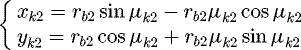
Take one end tooth surface as an example, the coordinate of standard tooth profile is shown in Figure 3. Two tooth profile equation are expressed as (2)
(2)
 (3)
(3)
Formulas (2) and (3) are the profile equation of left tooth and right tooth, respectively. Where r bi (i =1, 2) is the radius of base circle, μki (i =1, 2) is the roll angle of point k in the involute.
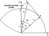 |
Fig. 3 Coordinate of standard tooth profile. |
3.1.2 Standard tooth surface equation
The tooth surfaces of double helical gear is involute helicoid. Figures 4 and 5 are its left and right tooth surface helix diagram, respectively.
The left tooth surface equation is expressed as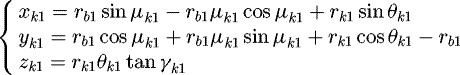 (4)
(4)
The right tooth surface equation is expressed as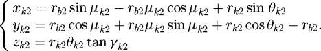 (5)
(5)
Equations (4) and (5) are all the equation of involute helicoid. Where, r bi (i = 1, 2) is the radius of base circle, μki (i = 1, 2) is the roll angle of point k in the involute, rki (i = 1, 2) is the radius of point k in the involute, θki (i = 1, 2) is the expansion angle of point k in the involute, γki (i = 1, 2) is the helix angle of ascent of point k in the involute, βki (i = 1, 2) is the helix angle of point k in the involute.
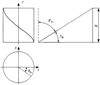 |
Fig. 4 Helix diagram of left tooth surface. |
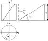 |
Fig. 5 Helix diagram of right tooth surface. |
3.2 Tooth surface equation of double helical gears after thermal deformation
3.2.1 Variation of tooth profile equation caused by thermal deformation
Still take the left tooth surface as an example, the left tooth profile after thermal deformation is shown in Figure 6. The tooth profile equation after thermal deformation can be expressed as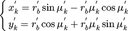 (6)
where
(6)
where 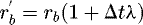 ,
,  ,
,  ,
,  is the radius of base circle after the thermal distortion,
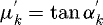
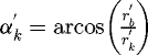
  is the roll angle of point k in the involute after the thermal distortion.
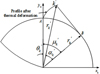 |
Fig. 6 Left tooth profile after thermal deformation. |
3.2.2 The tooth surface equation after thermal deformation
The helix diagram of left tooth surface and right surface after thermal deformation is shown in Figures 7 and 8, respectively.
The left tooth surface equation after thermal deformation is expressed as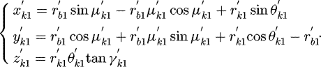 (7)
(7)
The right tooth surface equation after thermal deformation is expressed as (8)
where
(8)
where 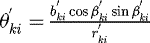 ,
, 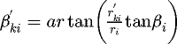 ,
,  ,
,  (i = 1, 2) is the radius of base circle after the thermal distortion,
  (i = 1, 2) is the roll angle of point k in the involute after the thermal distortion,
  (i = 1, 2) is the radius of point k in the involute after the thermal distortion,
 (i = 1, 2) is the expansion angle of point k in the involute after the thermal distortion,
  (i = 1, 2) is the helix angle of ascent of point k in the involute after the thermal distortion, βki’(i = 1, 2) is the helix angle of point k in the involute after the thermal distortion,
  is the tooth face width of point k in the involute after the thermal distortion, ri (i = 1, 2) is the radius of reference circle after the thermal distortion.
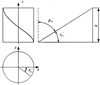 |
Fig. 7 Helix diagram of left tooth surface after deformation. |
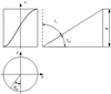 |
Fig. 8 Helix diagram of left tooth surface after deformation. |
4 Example
Taking the measured temperature gear as an example [1], the material of gear is 45 steel and the coefficient of linear expansion λ = 11.6e −6 c −1, room temperature t 0 = 25 °C. Table 1 shows other parameters of the gear. The tooth surface temperature distribution measured by Zhengzhou Institute of machinery [1] is shown in Figure 9. Because the installation error and machining error of double helical gear are not considered, the gear tooth temperature distribution of two tooth surfaces is the same.
According to Figure 9, the temperature equation along reference circle axial with a linear velocity of 130 m/s is deduced. (9)
(9)
According to formulas (4), (5), (7), (8). the tooth surface before and after thermal deformation are shown in Figures 10–13 (where, the x axis describes longitudinal direction, the y axis describes tooth thickness direction and the z axis describes radial direction).
Because the installation error and machining error of double helical gear are not considered, the thermal deformation of Figures 12 and 13 is the same. Take left tooth surface as an example, the difference of the tooth surface coordinates before and after thermal deformation is shown in Figure 14, the mean value of the difference of the tooth surface coordinates before and after thermal deformation is shown in Table 2. According to reference [1], Table 3 showed the modification of thermal deformation, which corresponds to the deformation of tooth thickness. In this paper, the diameter of reference circle is 199.36 mm, which is close to 200 mm in Table 4. Therefore, the modification can be taken as 0.009 mm. In Table 3, the mean value of the difference of the tooth surface coordinates along tooth thickness direction is 0.009627 mm. The error is one order of magnitude smaller than them.
When the installation/machining error of gear exists, the meshing path of two tooth surfaces change. Reference [12] gave the meshing path of left and right tooth surfaces under installation/machining error of gear (Fig. 15). The temperature of instantaneous contact points on the left/right tooth surface is assumed that still satisfies formula (9). The thermal deformation of two tooth surfaces is recalculated, the mean value of the difference of tooth thickness direction without and with considering installation error and machining error of gear is shown in Table 4. It can be found that thermal deformation of left and right tooth surfaces is difference and different modifications of thermal deformation are needed.
Parameters of double helical gear.
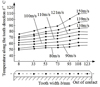 |
Fig. 9 Temperature of instantaneous meshing points. |
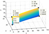 |
Fig. 10 Tooth surface 3D drawing before thermal deformation (left tooth surface). |
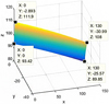 |
Fig. 11 Tooth surface 3D drawing before the thermal deformation (right tooth surface). |
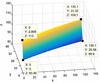 |
Fig. 12 Tooth surface 3D drawing after the thermal deformation (left tooth surface). |
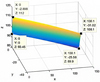 |
Fig. 13 Tooth surface 3D drawing after the thermal deformation (right tooth surface). |
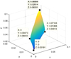 |
Fig. 14 Difference of the tooth surface coordinates before and after thermal deformation. |
Mean value of the difference of thermal deformation.
Modification of thermal deformation.
Mean value of the difference of tooth thickness direction without and with considering installation error and machining error of gear.
 |
Fig. 15 Path of tooth surface contact under installation error and machining error of gear. |
5 Conclusion
The calculation of gear thermal deformation is one of the keys to gear modification. Double helical gear is taken as the research object and a calculation method of thermal deformation is proposed. The temperature field is determined according the measured temperature of instantaneous meshing point and radial temperature formula. According to the structural characteristics of double helical gear, the standard equation for tooth surface is derived. On the basis, the thermal deformation equation of tooth surface is derived according to the tooth surface temperature field. Taking a temperature measuring gears as an example, the tooth surface has changed obviously before and after thermal deformation. Compared with the relevant data given in reference [1], the result is reasonable which verifies the feasibility of the proposed method. By calculating the thermal deformation of two surfaces when the installation error/machining error of gear exists, it can be found that the deformation of two tooth surfaces is different. That is to say, the left and right tooth surfaces should be modified with different amounts.
Acknowledgments
The research work is supported by National Natural Science Foundation of China (Grant No. 51475210), A Project of Shandong Province Higher Educational Science and Technology Program (Grant No. J17KA027) and major research project of Shandong province (Grant No. 2018GGX103035).
References
- The Directed committee of Gear notebook, Gear notebook second edition, China Machine PRESS, 2002, pp. 215 [Google Scholar]
- S. Baglioni, F. Cianetti, L. Landi, Influence of the addendum modification on spur gear efficiency, Mech. Mach. Theory 49 , 216–233 (2012) [Google Scholar]
- V.V. Simon, Influence of tooth modifications on tooth contact in face-hobbed spiral bevel gears, Mech. Mach. Theory 46 , 1980–1998 (2011) [Google Scholar]
- C. Wang, Optimization of tooth profile modification based on dynamic characteristics of helical gear pair, Iran J. Sci. Technol. Trans. Mech. Eng. 43, 5631–5639 (2019) [CrossRef] [Google Scholar]
- L. Bobach, R. Beilicke, D. Bartel et al., Thermal elastohydro dynamic simulation of involute spur gears incorporating mixed friction, Tribol. Int. 48 , 191–206 (2012) [Google Scholar]
- Q. Liang Heng, X. Yi Xing, W. Tong, et al., A calculation of bulk temperature and thermal deflection of gear tooth about profile modification, J. Shanghai Jiaotong Univ. 29 , 79–86 (1995) [Google Scholar]
- G. Xiansheng, W. Huanhuan, Z. Ganqing et al., Analysis of bulk temperature field and flash temperature for planet gear tooth, Trans. Chin. Soc. Agric. Mach. 42 , 209–216 (2011) [Google Scholar]
- N. Patir, H.S. Cheng, Prediction of the bulk temperature in spur gear based on finite element temperature analysis, Tribol. Trans. 22 , 25–36 (1979) [Google Scholar]
- K.L. Wang, H.S. Cheng, A numerical solution to the dynamic load, film thickness, and surface temperatures in spur gears, ASME J. Mech. Des. 103, 177–194 (1981) [Google Scholar]
- L. Guihua, F. Yetai, Research of the non-involution characteristic of thermal deformation gear, J. Harbin Inst. Technol. 38, 123–125 (2006) [Google Scholar]
- C. Wang, H. Yong Cui, Q. Ping Zhang, The derivation of transformation matrix before and after thermal distortion for modification, Proc. Inst. Mech. Eng. C 229, 1686–1692 (2015) [CrossRef] [Google Scholar]
- C. Wang, H. Yong Cui, Q. Ping Zhang et al., Contact model and tooth contact analysis of double helical gears with parallel-axis, crossed-axis and modification, Aust. J. Mech. Eng. 13, 1–8 (2015) [CrossRef] [Google Scholar]
Cite this article as: C. Wang, A calculation method of thermal deformation for double helical gear, Mechanics & Industry 20, 612 (2019)
All Tables
Mean value of the difference of tooth thickness direction without and with considering installation error and machining error of gear.
All Figures
|
Fig. 1 Flow diagram for calculation of thermal deformation of double helical gear. |
| In the text | |
|
Fig. 2 Schematic diagram of determining tooth surface temperature distribution. |
| In the text | |
|
Fig. 3 Coordinate of standard tooth profile. |
| In the text | |
|
Fig. 4 Helix diagram of left tooth surface. |
| In the text | |
|
Fig. 5 Helix diagram of right tooth surface. |
| In the text | |
|
Fig. 6 Left tooth profile after thermal deformation. |
| In the text | |
|
Fig. 7 Helix diagram of left tooth surface after deformation. |
| In the text | |
|
Fig. 8 Helix diagram of left tooth surface after deformation. |
| In the text | |
|
Fig. 9 Temperature of instantaneous meshing points. |
| In the text | |
|
Fig. 10 Tooth surface 3D drawing before thermal deformation (left tooth surface). |
| In the text | |
|
Fig. 11 Tooth surface 3D drawing before the thermal deformation (right tooth surface). |
| In the text | |
|
Fig. 12 Tooth surface 3D drawing after the thermal deformation (left tooth surface). |
| In the text | |
|
Fig. 13 Tooth surface 3D drawing after the thermal deformation (right tooth surface). |
| In the text | |
|
Fig. 14 Difference of the tooth surface coordinates before and after thermal deformation. |
| In the text | |
|
Fig. 15 Path of tooth surface contact under installation error and machining error of gear. |
| In the text | |
Current usage metrics show cumulative count of Article Views (full-text article views including HTML views, PDF and ePub downloads, according to the available data) and Abstracts Views on Vision4Press platform.
Data correspond to usage on the plateform after 2015. The current usage metrics is available 48-96 hours after online publication and is updated daily on week days.
Initial download of the metrics may take a while.